EP2055910B1 - Wasserpumpe - Google Patents
Wasserpumpe Download PDFInfo
- Publication number
- EP2055910B1 EP2055910B1 EP07860182A EP07860182A EP2055910B1 EP 2055910 B1 EP2055910 B1 EP 2055910B1 EP 07860182 A EP07860182 A EP 07860182A EP 07860182 A EP07860182 A EP 07860182A EP 2055910 B1 EP2055910 B1 EP 2055910B1
- Authority
- EP
- European Patent Office
- Prior art keywords
- rotation member
- end rotation
- driven
- water pump
- vacuum
- Prior art date
- Legal status (The legal status is an assumption and is not a legal conclusion. Google has not performed a legal analysis and makes no representation as to the accuracy of the status listed.)
- Expired - Fee Related
Links
- XLYOFNOQVPJJNP-UHFFFAOYSA-N water Substances O XLYOFNOQVPJJNP-UHFFFAOYSA-N 0.000 title claims abstract description 78
- 230000006698 induction Effects 0.000 claims abstract description 90
- 230000005540 biological transmission Effects 0.000 abstract description 14
- 230000001939 inductive effect Effects 0.000 abstract 3
- 230000008878 coupling Effects 0.000 description 25
- 238000010168 coupling process Methods 0.000 description 25
- 238000005859 coupling reaction Methods 0.000 description 25
- 239000000498 cooling water Substances 0.000 description 12
- 230000004907 flux Effects 0.000 description 11
- 230000002093 peripheral effect Effects 0.000 description 6
- 230000004048 modification Effects 0.000 description 5
- 238000012986 modification Methods 0.000 description 5
- 230000006866 deterioration Effects 0.000 description 4
- 238000009434 installation Methods 0.000 description 4
- 230000001133 acceleration Effects 0.000 description 2
- 229910052782 aluminium Inorganic materials 0.000 description 2
- XAGFODPZIPBFFR-UHFFFAOYSA-N aluminium Chemical compound [Al] XAGFODPZIPBFFR-UHFFFAOYSA-N 0.000 description 2
- 239000002826 coolant Substances 0.000 description 2
- 230000007423 decrease Effects 0.000 description 2
- 239000000446 fuel Substances 0.000 description 2
- 238000013021 overheating Methods 0.000 description 2
- 238000007789 sealing Methods 0.000 description 2
- 238000010792 warming Methods 0.000 description 2
- RYGMFSIKBFXOCR-UHFFFAOYSA-N Copper Chemical compound [Cu] RYGMFSIKBFXOCR-UHFFFAOYSA-N 0.000 description 1
- AZDRQVAHHNSJOQ-UHFFFAOYSA-N alumane Chemical group [AlH3] AZDRQVAHHNSJOQ-UHFFFAOYSA-N 0.000 description 1
- 238000002485 combustion reaction Methods 0.000 description 1
- 238000010276 construction Methods 0.000 description 1
- 238000001816 cooling Methods 0.000 description 1
- 229910052802 copper Inorganic materials 0.000 description 1
- 239000010949 copper Substances 0.000 description 1
- 230000000694 effects Effects 0.000 description 1
- 239000012530 fluid Substances 0.000 description 1
- 238000010438 heat treatment Methods 0.000 description 1
- 230000001771 impaired effect Effects 0.000 description 1
- 239000000463 material Substances 0.000 description 1
- 229910052751 metal Inorganic materials 0.000 description 1
- 239000002184 metal Substances 0.000 description 1
- 230000005405 multipole Effects 0.000 description 1
- 230000035515 penetration Effects 0.000 description 1
- 230000001105 regulatory effect Effects 0.000 description 1
- 238000000638 solvent extraction Methods 0.000 description 1
Images


Classifications
-
- F—MECHANICAL ENGINEERING; LIGHTING; HEATING; WEAPONS; BLASTING
- F01—MACHINES OR ENGINES IN GENERAL; ENGINE PLANTS IN GENERAL; STEAM ENGINES
- F01P—COOLING OF MACHINES OR ENGINES IN GENERAL; COOLING OF INTERNAL-COMBUSTION ENGINES
- F01P5/00—Pumping cooling-air or liquid coolants
- F01P5/10—Pumping liquid coolant; Arrangements of coolant pumps
- F01P5/12—Pump-driving arrangements
-
- F—MECHANICAL ENGINEERING; LIGHTING; HEATING; WEAPONS; BLASTING
- F04—POSITIVE - DISPLACEMENT MACHINES FOR LIQUIDS; PUMPS FOR LIQUIDS OR ELASTIC FLUIDS
- F04D—NON-POSITIVE-DISPLACEMENT PUMPS
- F04D13/00—Pumping installations or systems
- F04D13/02—Units comprising pumps and their driving means
- F04D13/021—Units comprising pumps and their driving means containing a coupling
- F04D13/022—Units comprising pumps and their driving means containing a coupling a coupling allowing slip, e.g. torque converter
-
- F—MECHANICAL ENGINEERING; LIGHTING; HEATING; WEAPONS; BLASTING
- F04—POSITIVE - DISPLACEMENT MACHINES FOR LIQUIDS; PUMPS FOR LIQUIDS OR ELASTIC FLUIDS
- F04D—NON-POSITIVE-DISPLACEMENT PUMPS
- F04D13/00—Pumping installations or systems
- F04D13/02—Units comprising pumps and their driving means
- F04D13/021—Units comprising pumps and their driving means containing a coupling
- F04D13/024—Units comprising pumps and their driving means containing a coupling a magnetic coupling
- F04D13/025—Details of the can separating the pump and drive area
-
- F—MECHANICAL ENGINEERING; LIGHTING; HEATING; WEAPONS; BLASTING
- F04—POSITIVE - DISPLACEMENT MACHINES FOR LIQUIDS; PUMPS FOR LIQUIDS OR ELASTIC FLUIDS
- F04D—NON-POSITIVE-DISPLACEMENT PUMPS
- F04D13/00—Pumping installations or systems
- F04D13/02—Units comprising pumps and their driving means
- F04D13/021—Units comprising pumps and their driving means containing a coupling
- F04D13/024—Units comprising pumps and their driving means containing a coupling a magnetic coupling
- F04D13/026—Details of the bearings
-
- F—MECHANICAL ENGINEERING; LIGHTING; HEATING; WEAPONS; BLASTING
- F04—POSITIVE - DISPLACEMENT MACHINES FOR LIQUIDS; PUMPS FOR LIQUIDS OR ELASTIC FLUIDS
- F04D—NON-POSITIVE-DISPLACEMENT PUMPS
- F04D13/00—Pumping installations or systems
- F04D13/02—Units comprising pumps and their driving means
- F04D13/021—Units comprising pumps and their driving means containing a coupling
- F04D13/024—Units comprising pumps and their driving means containing a coupling a magnetic coupling
- F04D13/027—Details of the magnetic circuit
Definitions
- the present invention relates to variable volume type water pumps used in engines mounted in, for example, vehicles and the like.
- Patent document JP 2001-90537 discloses a water pump wherein a first rotation member (drive-end rotation member) whereto a water pump pulley is fixed and a second rotation member (driven-end rotation member) whereto a pump impeller is fixed are connected via a multiplate wet clutch having a viscous fluid as a medium. Furthermore, provision inside a cooling water channel of a temperature sensitive member deforming according to a temperature of cooling water in order to disconnect the multiplate wet clutch is disclosed.
- the water pump specified in this patent document JP 2001-90537 is configured such that, when a water temperature is low, driving of the water pump is substantially stopped in order to reduce friction and prevent deterioration of fuel efficiency, and furthermore, when a water temperature is high, the clutch is set to an engaged condition and rotation of the first rotation member is transmitted to the second rotation member.
- variable volume type water pumps items wherein transmission of rotation from the drive-end rotation member to the driven-end rotation member is carried out in a non-contact condition.
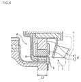
- the components of this water pump related to the transmission of rotation from the drive-end rotation member to the driven-end rotation member are shown in FIG. 4 .
- an interval between a drive-end rotation member 101 and a driven-end rotation member 103 is partitioned by a dividing wall 105.
- a permanent magnet 102 mounted on the drive-end rotation member 101 and an induction ring 104 mounted on the driven-end rotation member 103 are provided so as to be opposed with a prescribed interval therebetween.
- the induction ring 104 is configured having an aluminum ring member 104b mounted on an outer periphery of a magnetic core 104a.
- the torque transmitted to the driven-end rotation member 103 is changed by changing an overlap amount (degree of mutual overlap in the axial direction) L2 of the permanent magnet 102 of the drive-end rotation member 101 and the ring member 104b of the induction ring 104 in an axial direction (rotation axis direction).
- an overlap amount (degree of mutual overlap in the axial direction) L2 of the permanent magnet 102 of the drive-end rotation member 101 and the ring member 104b of the induction ring 104 in an axial direction (rotation axis direction).
- Document US 6,007,303 A further discloses a controllable motor vehicle coolant pump driven by an internal combustion engine via a belt pulley connected to a driving shaft.
- the pump does not require a shaft seal for sealing the flow chamber against the bearing casing of the driving belt pulley, and reduces fuel consumption and exhaust gas emission during the entire operating range of the engine.
- the pump comprises two opposing clutch halves mounted on two clutch shafts.
- the impeller of the coolant pump is driven by a permanently magnetic clutch.
- One clutch half is comprised of a multipole magnetic disc magnetized in sectors on one of the two clutch shafts.
- the other clutch half comprises a disk made of hysteresis material or a disk with a copper disc arranged therein mounted on the other clutch shaft.
- the width of the air gap between the two clutch halves is variable depending on the given operational condition of the engine.
- the magnetic field from the permanent magnet 102 extends not only to the ring member 104b of the induction ring 104, but also extends to the surroundings thereof, and flux leakage occurs. That is to say, lines of magnetic force from the permanent magnet 102 occur so as to spread out further than this permanent magnet 102 to an outer side in an axial direction. As a result, an efficiency of transmission of torque to the driven-end rotation member 103 is impaired.
- the present invention takes this type of problem into consideration, and an object thereof is to provide a variable volume type water pump facilitating more compact designs.
- a water pump configured such that rotation is transmitted in a non-contact condition from a drive-end rotation member whereto rotation is transmitted from an engine to a driven-end rotation member having a pump impeller includes a pair of magnets provided on one of the drive-end rotation member and the driven-end rotation member so as to be mutually opposed with different polarities; an induction body provided on the other of the drive-end rotation member and the driven-end rotation member so as to form a prescribed interval between the pair of magnets; and a moving means moving at least one of the pair of magnets and the induction body with respect to another thereof in a rotation axis direction and changing a degree of mutual overlap (overlap amount) of the pair of magnets and the induction body in the rotation axis direction thereof.
- a magnetic field is generated between the pair of magnets of the drive-end rotation member. Furthermore, when the rotation of the engine is transmitted and the drive-end rotation member rotates, the magnetic field acting on the induction body changes. As a result of this, an induction current in a direction obstructing the magnetic field change is generated in the induction body. A torque is generated in the induction body pursuant to this induction-current generation. As a result, the driven-end rotation member rotates and the water pump drives. Furthermore, if the overlap amount is changed by the moving means, the induction current generated in the induction body changes and the torque transmitted to the driven-end rotation member changes. As a result, a pump flow volume of the water pump changes.
- the water pump does not increase in size in the axial direction, and a compact configuration thereof can be achieved.
- deterioration of mounting characteristics at locations of installation of the water pump can be avoided.
- the moving means includes a vacuum chamber provided on one of the drive-end rotation member and the driven-end rotation member and a movable member moving in the rotation axis direction in accordance with a vacuum introduced into this vacuum chamber, and that the pair of magnets or the induction body is provided on the movable member.
- the movable member moves in the rotation axis direction in accordance with the vacuum introduced into the vacuum chamber, the position in the rotation axis direction of the pair of magnets or the induction body mounted on this movable member changes and the overlap amount changes. Accordingly, the overlap amount can be set in accordance with the vacuum introduced into the vacuum chamber, and pursuant to this, the pump flow volume of the water pump can be continuously changed.
- the vacuum chamber includes the movable member and a guide member guiding a motion of this movable member towards the rotation axis direction.
- an intake vacuum (suction-pipe vacuum) of the engine is used as the vacuum introduced into the vacuum chamber.
- the degree of mutual overlap of the pair of magnets and the induction body in the rotation axis direction (overlap amount) is set larger than "0" and the water pump is driven, torque can be efficiently transmitted to the driven-end rotation member and drive loss due to flux leakage can be reduced. Meanwhile, if the overlap amount is set to "0", the torque transmitted to the driven-end rotation member becomes substantially “0", and driving of the water pump can be stopped. Accordingly, it becomes no longer necessary to secure an offset amount in the rotation axis direction for the pair of magnets and the induction body, the water pump does not increase in size in the axial direction, and a compact configuration thereof can be achieved. In addition, deterioration of mounting characteristics at locations of installation of the water pump can be avoided.
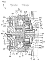
- FIG. 1 is a cross-section view showing one embodiment of a variable volume type water pump according to the present invention.
- FIG. 1 is a cross-section view showing one embodiment of a variable volume type water pump
- FIG. 2 and FIG. 3 show an enlarged view of a section related to transmission of rotation from a drive-end rotation member to a driven-end rotation member of the water pump of FIG. 1 .
- FIG. 2 a condition of the water pump wherein a vacuum is not introduced into a vacuum chamber
- FIG. 3 a condition of the water pump wherein a vacuum is introduced into a vacuum chamber
- a water pump 10 includes a drive-end rotation member 20 having a water pump pulley 21, a driven-end rotation member 30 having a pump impeller 31, and a dividing wall 40 partitioning an interval between the drive-end rotation member 20 and the driven-end rotation member 30. Furthermore, as explained hereinafter, transmission of rotation from the drive-end rotation member 20 to the driven-end rotation member 30 is carried out in a non-contact condition.
- the drive-end rotation member 20 and the driven-end rotation member 30 are provided on a housing 11 of an engine so as to be capable of rotating freely.
- the drive-end rotation member 20 includes the water pump pulley 21, a mounting plate 22, a drive shaft member 23, a bracket guide member 24, a magnet bracket 25, and a magnet coupling 26, and is configured such that these rotate as one about an axis A1.
- the drive-end rotation member 20 has a shape with substantial rotation symmetry about the axis A1.
- the driven-end rotation member 30 includes the pump impeller 31 and an induction ring 32 having an induction body, and is configured such that these rotate as one about an axis B1.
- the driven-end rotation member 30 has a shape with substantial rotation symmetry about the axis B1. It should be noted that the axis A1 and the axis B1 are provided coaxially.
- the drive shaft member 23 of the drive-end rotation member 20 is supported via a bearing 13 so as to be capable of rotation by a boss section 12a of a support case 12 secured to the housing 11.
- the drive shaft member 23 includes a cylindrical shaft section 23a extending along an axial direction (rotation axis direction) and a flange section 23b provided at an outer side in a radial direction from this shaft section 23a.
- An interior space of the shaft section 23a constitutes a vacuum introduction channel 52 for introducing a vacuum into a vacuum chamber 50, explained hereinafter.
- the mounting plate 22 and the bracket guide member 24 are mounted as one to the drive shaft member 23.
- the mounting plate 22 is secured to an axial-direction end section (a left end section of FIG. 1 ) of the shaft section 23a.
- the water pump pulley 21 is secured to the mounting plate 22 using bolts 28.
- the water pump pulley 21 is connected via, for example, a V-belt, etc. to a pulley of a crankshaft of the engine.
- a vacuum introduction tube 51 is provided at a central axial side of the mounting plate 22.
- An air seal 14 and a bearing 15 are interposed between a section at a central axial side of the mounting plate 22 and the vacuum introduction tube 51.
- An end side of the vacuum introduction tube 51 communicates with a vacuum supply channel extending from a vacuum generation source.
- Another end of the vacuum introduction tube 51 communicates with the above-described vacuum introduction channel 52.
- the bracket guide member 24 guides a motion of the magnet bracket 25 in the axial direction and includes an inner guide member 24a and an outer guide member 24b as a pair.
- the inner guide member 24a and the outer guide member 24b are provided so as to be opposed with a prescribed interval therebetween. Furthermore, a space enclosed by the two guide members 24a, 24b and the magnet bracket 25 constitutes the vacuum chamber 50. That is to say, the two guide members 24a, 24b of the bracket guide member 24 and the magnet bracket 25 form wall members of the vacuum chamber 50.
- the vacuum chamber 50 is a sealed space formed with a substantially toric shape inside the drive-end rotation member 20 and extending in the axial direction and is provided at one side (a Y1 direction side of FIG. 1 ) of the magnet bracket 25 in the axial direction.
- the vacuum chamber 50 communicates with the exterior thereof (in this case, a vacuum introduction channel 53) via only a vacuum introduction hole 24c provided in the bracket guide member 24.
- the vacuum introduction hole 24c is formed at a plurality of locations in a circumferential direction of the bracket guide member 24.
- the vacuum introduction channel 53 is a space formed by the flange section 23b of the drive shaft member 23 and the inner guide member 24a of the bracket guide member 24, and the vacuum chamber 50 communicates with the vacuum introduction channel 52 via this vacuum introduction channel 53.
- the magnet bracket 25 constitutes a support member supporting the magnet coupling 26, and in addition, is a member capable of moving in the axial direction in accordance with a vacuum introduced into the vacuum chamber 50.
- the magnet bracket 25 forms a section of a wall member of the vacuum chamber 50.
- the magnet bracket 25 is provided with an inner cylindrical section 25a and an outer cylindrical section 25b as a pair disposed in parallel at an inside and an outside in a radial direction and with a prescribed interval therebetween.
- the magnet bracket 25 is housed within the two guide members 24a, 24b of the bracket guide member 24 in a condition so as to be capable of sliding in the axial direction.
- the magnet bracket 25 is provided so as to be capable of moving in the axial direction along the two guide members 24a, 24b in accordance with the vacuum introduced into the vacuum chamber 50 and of changing an axial direction position thereof.
- the axial direction position of the magnet bracket 25 (the axial direction position of an end section of the magnet bracket 25 at the Y1 direction side thereof) is capable of changing continuously between X1 (a condition shown in FIG. 3 ) and X2 (a condition shown in FIG. 2 ).
- a distance between the X1 and X2 axial direction positions of the magnet bracket 25 is equivalent to a maximum value of an overlap amount L1 described hereinafter.
- a plurality of (in this example, 3) protrusions 25c extending towards the inner guide member 24a of the bracket guide member 24 and making contact with an outer peripheral surface of this inner guide member 24a are formed on an inner peripheral side of the inner cylindrical section 25a. Furthermore, a plurality of (in this example, 3) protrusions 25d extending towards the outer guide member 24b of the bracket guide member 24 and making contact with an inner peripheral surface of this outer guide member 24b are formed on an outer peripheral side of the outer cylindrical section 25b. Using these protrusions 25c, 25d, the vacuum chamber 50 is maintained in a state of substantial sealing.
- a spring 54 is provided inside the vacuum chamber 50.
- the magnet bracket 25 is biased towards another side (a Y2 direction side of FIG. 1 ) in the axial direction by an elastic force of the spring 54.
- a stopper 29 is provided on the bracket guide member 24 in order to regulate the motion of the magnet bracket 25 towards the Y2 direction side.
- Vacuum is introduced into the vacuum chamber 50 from a vacuum generation source via the vacuum introduction tube 51, the vacuum introduction channels 52, 53, and the vacuum introduction hole 24c.
- a vacuum generation source for example, an intake vacuum (suction-pipe vacuum) of the engine can be used as a vacuum generation source.
- the intake vacuum of the engine is, for example, introduced from suction piping, etc. of the engine via a pressure control valve, etc. into the vacuum chamber 50.
- the vacuum introduced to the vacuum chamber 50 is controlled by performing opening and closing control of the pressure control valve in accordance with control signals from a control device based on an engine operation condition.
- the magnet coupling 26 is formed by a pair of toric permanent magnets 26a, 26b of equivalent width in the axial direction (longitudinal direction).
- the permanent magnets 26a, 26b of the magnet coupling 26 are provided at an inside and an outside in a radial direction so as to be opposed with a prescribed interval therebetween.
- the polarities of opposing sections of the small-diameter permanent magnet 26a disposed at an inner side and the large-diameter permanent magnet 26b disposed at an outer side are mutually different.
- the inner-side permanent magnet 26a is secured to an outer peripheral surface of the inner cylindrical section 25a of the magnet bracket 25.
- the outer-side permanent magnet 26b is secured to an inner peripheral surface of the outer cylindrical section 25b of the magnet bracket 25.
- the driven-end rotation member 30 is housed within a cooling water channel W wherethrough cooling water flows.
- the pump impeller 31 of this driven-end rotation member 30 is supported via an underwater bearing 18 by a shaft member 17 secured to the housing 11 so as to be capable of rotating. Cooling water in the cooling water channel W is discharged to an exterior section pursuant to rotation of this pump impeller 31.
- the induction ring 32 for rotating the pump impeller 31 is secured to the pump impeller 31.
- the induction ring 32 includes a mounting section 32a for mounting on the pump impeller 31 and a toric induction section 32b extending along an axial direction from an outer end section of this mounting section 32a towards a Y1-direction side.
- This induction section 32b is provided as an induction current generating section (induction body) for generating torque transmitted to the driven-end rotation member 30 pursuant to rotation of the drive-end rotation member 20.
- at least a portion containing the induction section 32b is formed of aluminum. It should be noted that the portion of the induction ring 32 containing the induction section 32b can be formed of a metal other than aluminum.
- the induction section 32b is provided parallel to the permanent magnets 26a, 26b of the magnet coupling 26 of the drive-end rotation member 20. Furthermore, the induction section 32b is disposed in a substantially central position of the permanent magnets 26a, 26b of the magnet coupling 26 in a radial direction. In addition, the induction section 32b is disposed at a position such that, except when the axial direction position of the magnet bracket 25 is X1, the positions in the axial direction of the induction section 32b and of the permanent magnets 26a, 26b of the magnet coupling 26 mutually overlie (overlap).
- An interval between the induction section 32b and the permanent magnets 26a, 26b of the magnet coupling 26 is partitioned by a curved section 40a of the dividing wall 40 having a U-shaped cross section. Accordingly, the curved section 40a of the dividing wall 40 is disposed so as to form a prescribed interval at a pair of inner and outer sides of the induction section 32b in the radial direction, and furthermore, the permanent magnets 26a, 26b of the magnet coupling 26 are disposed so as to form a prescribed interval at a pair of inner and outer sides of the curved section 40a of the dividing wall 40 in a radial direction.
- the dividing wall 40 is provided in a section between the drive-end rotation member 20 and the driven-end rotation member 30.
- the dividing wall 40 is secured to the housing 11.
- the dividing wall 40 has a shape following a shape of the section between the drive-end rotation member 20 and the driven-end rotation member 30 and includes the above-described curved section 40a.
- the interval between the drive-end rotation member 20 and the driven-end rotation member 30 is separated by this dividing wall 40 such that penetration of cooling water into the side of the drive-end rotation member 20 is prevented. Therefore, transmission of rotation from the drive-end rotation member 20 to the driven-end rotation member 30 is carried out in a non-contact condition.
- this transmission of rotation from the drive-end rotation member 20 to the driven-end rotation member 30 is explained.
- the drive-end rotation member 20, configured as explained above, is driven to rotate due to the transmission of rotation of the crankshaft to the water pump pulley 21 upon engine drive.
- a magnetic field is generated between the permanent magnets 26a, 26b of the magnet coupling 26 of the drive-end rotation member 20.
- substantially-linear lines of magnetic force extending from one of the permanent magnets 26a, 26b of the magnet coupling 26 to the other thereof are generated. That is to say, the lines of magnetic force are generated with almost no widening beyond the permanent magnets 26a, 26b to an outer side in the axial direction. For this reason, almost no leakage of flux beyond the permanent magnets 26a, 26b to an outer side in the axial direction occurs.
- the magnetic field from the permanent magnets 26a, 26b of the magnet coupling 26 acts upon the induction section 32b of the induction ring 32 of the driven-end rotation member 30 enclosed between the permanent magnets 26a, 26b of the magnet coupling 26.
- the configuration is such that the driven-end rotation member 30 does not rotate and the water pump 10 does not drive.
- a moving means is provided to move the permanent magnets 26a, 26b of the magnet coupling 26 in the axial direction with respect to the induction section 32b of the induction ring 32 and to change the overlap amount in the axial direction (degree of mutual overlap in the axial direction) L1 of the permanent magnets 26a, 26b of the magnet coupling 26 and the induction section 32b of the induction ring 32.
- the configuration is such that the torque transmitted to the driven-end rotation member 30 is changed due to changing of the overlap amount L1 using the moving means. As a result of this, a rotation speed of the driven-end rotation member 30 is changed and a volume of discharge (pump flow volume) of cooling water by the water pump 10 is changed.
- the above-explained moving means includes the vacuum chamber 50 and the magnet bracket 25 acting as a movable member moving in the axial direction in accordance with the vacuum introduced into this vacuum chamber 50.
- the magnet bracket 25 moves along the axial direction in accordance with the vacuum introduced into the vacuum chamber 50, and in line with this, the overlap amount L1 is set.
- the magnet bracket 25 In a case wherein vacuum is not introduced into the vacuum chamber 50, the magnet bracket 25 is biased towards a Y2 direction side by the elastic force of the spring 54 and moves as far as a position regulated by the stopper 29. Specifically, the axial direction position of an end section of the magnet bracket 25 on the Y1 direction side thereof becomes the X2 position.
- the overlap amount L1 is equivalent to a width of the permanent magnets 26a, 26b in the axial direction and is maximized. Accordingly, the induction current generated in the induction ring 32 is maximized in this condition, and therefore, the torque transmitted to the driven-end rotation member 30 is maximized. As a result, the pump flow volume of the water pump 10 is maximized.
- the larger the vacuum introduced into the vacuum chamber 50 the smaller the overlap amount L1 due to motion of the magnet bracket 25 towards the Y1 direction side against the elastic force of the spring 54.
- the overlap amount L1 becomes smaller, the induction current generated in the induction ring 32 becomes smaller and the torque transmitted to the driven-end rotation member 30 becomes smaller.
- the rotation speed of the driven-end rotation member 30 decreases and the pump flow volume of the water pump 10 decreases. Therefore, for example, at cold times such as when the engine is started, the overlap amount L1 can be made small and the pump flow volume of the water pump 10 can be reduced in order to achieve rapid heating.
- the smaller the vacuum introduced into the vacuum chamber 50 the larger the overlap amount L1 due to motion of the magnet bracket 25 towards the Y2 direction side.
- the overlap amount L1 becomes larger, the induction current generated in the induction ring 32 becomes larger and the torque transmitted to the driven-end rotation member 30 becomes larger.
- the rotation speed of the driven-end rotation member 30 increases and the pump flow volume of the water pump 10 increases. Therefore, for example, at hot times such as after warming-up of the engine, the overlap amount L1 can be made large and the pump flow volume of the water pump 10 can be increased in order to increase the cooling efficiency
- the water pump 10 is configured such that the pump flow volume can be continuously changed in accordance with the overlap amount L1 set depending on the vacuum introduced into the vacuum chamber 50. Furthermore, in this example, the water pump 10 is configured such that the magnetic field acting on the induction ring 32 of the driven-end rotation member 30 and torque transmitted to the driven-end rotation member 30 are generated by the magnet coupling 26 of the drive-end rotation member 20.
- the permanent magnets 26a, 26b of the magnet coupling 26 are disposed so as to be mutually opposed with different polarities, and therefore, substantially-linear lines of magnetic force extending from one of the permanent magnets 26a, 26b of the magnet coupling 26 to the other thereof are generated and almost no leakage of flux beyond the permanent magnets 26a, 26b to an outer side in the axial direction occurs.
- the overlap amount L1 is set larger than 0 and the water pump 10 is driven, torque can be efficiently transmitted to the driven-end rotation member 30 and drive loss due to flux leakage can be reduced.
- the overlap amount L1 is set to "0"
- the torque transmitted to the driven-end rotation member 30 becomes substantially “0”
- driving of the water pump 10 can be stopped.
- the overlap amount L1 is set to "0”
- an induction current is generated in the induction ring 32 of the driven-end rotation member 30 due to that flux leakage, and therefore, a torque transmitted to the driven-end rotation member 30 is generated and the water pump 10 is driven.
- the component parts in the form of the drive-end rotation member 20, the driven-end rotation member 30, and the dividing wall 40 and the shapes and disposition locations, etc. thereof are not limited to the above-explained case alone and a wide range of modifications are possible.
- the narrower the interval between the permanent magnets 26a, 26b of the magnet coupling 26 and the induction section 32b of the induction ring 32 the more efficient the transmission of torque to the driven-end rotation member 30 becomes.
- the configuration is such that the overlap amount L1 can be changed
- the component parts in the form of the magnet bracket 25 of the drive-end rotation member 20, the vacuum chamber 50, and the vacuum introduction channels 52, 53, etc. and the shapes and disposition locations, etc. thereof are not limited only to the above-explained case alone and a wide range of modifications are possible.
- the configuration can be such that the larger the vacuum introduced into the vacuum chamber 50, the larger the overlap amount L1.
- the configuration can be such that other than vacuum is used to change the overlap amount.
- positive pressure can be used in place of vacuum.
- a hydraulic actuator or electrical actuator, etc. can be used.
- the configuration is such that the magnet coupling 26 is provided on the drive-end rotation member 20 and the induction ring 32 is provided on the driven-end rotation member 30 in the above-explained example, in contrast to this case, the configuration can be such that an induction ring is provided on a drive-end rotation member and a magnet coupling is provided on a driven-end rotation member. Furthermore, although the configuration is such that the magnet coupling 26 moves in the axial direction in the above-explained example, in contrast to this case, the configuration can be such that the induction ring 32 is moved in the axial direction.
Landscapes
- Engineering & Computer Science (AREA)
- Mechanical Engineering (AREA)
- General Engineering & Computer Science (AREA)
- Chemical & Material Sciences (AREA)
- Combustion & Propulsion (AREA)
- Structures Of Non-Positive Displacement Pumps (AREA)
- Dynamo-Electric Clutches, Dynamo-Electric Brakes (AREA)
Claims (4)
- Wasserpumpe (10), die so konfiguriert ist, dass eine Drehung in einem Nichtkontaktzustand von einem antriebsendigen Drehelement (20), an das die Drehung von einem Motor übertragen wird, zu einem abtriebsendigen Drehelement (30) mit einem Pumpenflügelrad (31) übertragen wird, wobei die Wasserpumpe (10) dadurch gekennzeichnet ist, dass sie aufweist:ein Paar von Magneten (26a, 26b), die auf jeweils dem antriebsendigen Drehelement (20) oder dem abtriebsendigen Drehelement (30) angeordnet sind, so dass sie einander mit ihren unterschiedlichen Polungen gegenüberliegen;einen Induktionskörper, der auf dem jeweils anderen von entweder dem antriebsendigen Drehelement (20) oder dem abtriebsendigen Drehelement (30) angeordnet ist, um einen vorgeschriebenen Abstand zwischen dem Paar von Magneten (26a, 26b) auszubilden; undeine Bewegungseinrichtung, die entweder das Paar von Magneten (26a, 26b) und/oder den Induktionskörper relativ zueinander in einer Drehachsrichtung bewegt und einen Grad der gegenseitigen Überlappung des Paars von Magneten (26a, 26b) und des Induktionskörpers in der Drehachsrichtung verändert.
- Wasserpumpe (10) nach Anspruch 1, wobei:die Bewegungseinrichtung eine Vakuumkammer (50) aufweist, die auf entweder dem antriebsendigen Drehelement (20) oder dem abtriebsendigen Drehelement (30) oder einem beweglichen Element (25) angeordnet ist, das sich in der Drehachsenrichtung entsprechend einem Vakuum bewegt, das in der Vakuumkammer (50) erzeugt wird, unddas Paar von Magneten (26a, 26b) oder der Induktionskörper auf dem beweglichen Element (25) angeordnet ist.
- Wasserpumpe (10) nach Anspruch 2, wobei:die Vakuumkammer (50) das bewegliche Element (25) und ein Führungselement (24a, 24b) aufweist, das eine Bewegung dieses beweglichen Elements (25) in Richtung der Drehachsenrichtung führt.
- Wasserpumpe (10) nach Anspruch 2 oder 3, wobei:ein Einlassvakuum des Motors in der Vakuumkammer (50) erzeugt wird.
Applications Claiming Priority (2)
| Application Number | Priority Date | Filing Date | Title |
|---|---|---|---|
| JP2006351938A JP4429307B2 (ja) | 2006-12-27 | 2006-12-27 | ウォーターポンプ |
| PCT/JP2007/074953 WO2008078774A1 (ja) | 2006-12-27 | 2007-12-26 | ウォーターポンプ |
Publications (3)
| Publication Number | Publication Date |
|---|---|
| EP2055910A1 EP2055910A1 (de) | 2009-05-06 |
| EP2055910A4 EP2055910A4 (de) | 2010-05-05 |
| EP2055910B1 true EP2055910B1 (de) | 2011-03-23 |
Family
ID=39562565
Family Applications (1)
| Application Number | Title | Priority Date | Filing Date |
|---|---|---|---|
| EP07860182A Expired - Fee Related EP2055910B1 (de) | 2006-12-27 | 2007-12-26 | Wasserpumpe |
Country Status (6)
| Country | Link |
|---|---|
| US (1) | US8079828B2 (de) |
| EP (1) | EP2055910B1 (de) |
| JP (1) | JP4429307B2 (de) |
| CN (1) | CN101395354B (de) |
| DE (1) | DE602007013416D1 (de) |
| WO (1) | WO2008078774A1 (de) |
Families Citing this family (13)
| Publication number | Priority date | Publication date | Assignee | Title |
|---|---|---|---|---|
| GB2478970B (en) * | 2010-03-25 | 2016-08-17 | Concentric Birmingham Ltd | Pump with fluid actuated magnetic coupling |
| CN103201475A (zh) * | 2010-09-07 | 2013-07-10 | 皮尔伯格泵技术有限责任公司 | 机械式冷却剂泵 |
| JP2012092900A (ja) * | 2010-09-30 | 2012-05-17 | Aisin Seiki Co Ltd | 流体ポンプ |
| EP2543903B1 (de) * | 2011-07-04 | 2014-03-26 | Pierburg Pump Technology Italy S.p.A. | Mechanische, von Verbrennungsmotor betriebene Flüssigkeitspumpe |
| US9511178B2 (en) * | 2012-07-09 | 2016-12-06 | Medtronic, Inc. | Reducing centrifugal pump bearing wear through dynamic magnetic coupling |
| JP6053935B2 (ja) | 2012-08-23 | 2016-12-27 | ピールブルグ パンプ テクノロジー ゲゼルシャフト ミット ベシュレンクテル ハフツングPierburg Pump Technology GmbH | 燃焼機関によって駆動される機械式流体ポンプ |
| CN104812640B (zh) * | 2012-08-23 | 2017-06-09 | 皮尔伯格泵技术有限责任公司 | 气动制动辅助装置 |
| EP2888496B1 (de) * | 2012-08-23 | 2016-06-22 | Pierburg Pump Technology GmbH | Mechanische verbrennungsmotorbetriebene flüssigkeitspumpe |
| DE102013113362B4 (de) * | 2013-12-03 | 2015-10-22 | Pierburg Gmbh | Regelbare Pumpe für eine Verbrennungskraftmaschine |
| US9771938B2 (en) | 2014-03-11 | 2017-09-26 | Peopleflo Manufacturing, Inc. | Rotary device having a radial magnetic coupling |
| US9920764B2 (en) | 2015-09-30 | 2018-03-20 | Peopleflo Manufacturing, Inc. | Pump devices |
| WO2018193488A1 (ja) * | 2017-04-17 | 2018-10-25 | 株式会社Tbk | ウォータポンプ |
| CN114837792A (zh) | 2021-03-10 | 2022-08-02 | 美普盛(上海)汽车零部件有限公司 | 一种带膨胀补偿密封件的电动冷却液泵 |
Family Cites Families (13)
| Publication number | Priority date | Publication date | Assignee | Title |
|---|---|---|---|---|
| US2230717A (en) * | 1939-10-24 | 1941-02-04 | Gilbert & Barker Mfg Co | Pumping means |
| US2725185A (en) * | 1952-11-04 | 1955-11-29 | William L Willcox | Vacuum controlled drive for fans |
| US4065234A (en) * | 1975-12-22 | 1977-12-27 | Nihon Kagaku Kizai Kabushiki Kaisha | Magnetically driven rotary pumps |
| CH670286A5 (de) * | 1986-06-04 | 1989-05-31 | Sulzer Ag | |
| EP0855515B1 (de) | 1997-01-22 | 2002-12-18 | Eugen Dr. Schmidt | Regelbare Kühlmittelpumpe für Kraftfahrzeuge |
| JP2000125541A (ja) | 1998-10-16 | 2000-04-28 | Toshiba Corp | マグネットカップリング構造体 |
| JP2000257428A (ja) | 1999-03-03 | 2000-09-19 | Honda Motor Co Ltd | 内燃機関のウオータポンプ構造 |
| JP4259665B2 (ja) | 1999-03-24 | 2009-04-30 | 本田技研工業株式会社 | 内燃機関の補機取付け構造 |
| JP4174930B2 (ja) | 1999-09-24 | 2008-11-05 | いすゞ自動車株式会社 | ウォータポンプ |
| CN2413029Y (zh) * | 1999-10-19 | 2001-01-03 | 龙口市汽车风扇离合器厂 | 汽车水泵温控电磁风扇离合器总成 |
| JP2005233044A (ja) * | 2004-02-18 | 2005-09-02 | Aisin Seiki Co Ltd | 冷却液ポンプ |
| EP1801420A3 (de) | 2005-12-23 | 2009-10-21 | H. Wernert & Co. oHG | Kreiselpumpe mit permanentmagnetischer berührungsfreier Radialdrehkupplung |
| JP2007285268A (ja) | 2006-04-20 | 2007-11-01 | Mitsubishi Motors Corp | ウォータポンプ |
-
2006
- 2006-12-27 JP JP2006351938A patent/JP4429307B2/ja not_active Expired - Fee Related
-
2007
- 2007-12-26 EP EP07860182A patent/EP2055910B1/de not_active Expired - Fee Related
- 2007-12-26 US US12/223,028 patent/US8079828B2/en not_active Expired - Fee Related
- 2007-12-26 CN CN200780007788.7A patent/CN101395354B/zh not_active Expired - Fee Related
- 2007-12-26 WO PCT/JP2007/074953 patent/WO2008078774A1/ja not_active Ceased
- 2007-12-26 DE DE602007013416T patent/DE602007013416D1/de active Active
Also Published As
| Publication number | Publication date |
|---|---|
| US8079828B2 (en) | 2011-12-20 |
| JP4429307B2 (ja) | 2010-03-10 |
| DE602007013416D1 (de) | 2011-05-05 |
| US20090022606A1 (en) | 2009-01-22 |
| EP2055910A4 (de) | 2010-05-05 |
| CN101395354B (zh) | 2010-09-29 |
| JP2008163779A (ja) | 2008-07-17 |
| CN101395354A (zh) | 2009-03-25 |
| WO2008078774A1 (ja) | 2008-07-03 |
| EP2055910A1 (de) | 2009-05-06 |
Similar Documents
| Publication | Publication Date | Title |
|---|---|---|
| US8079828B2 (en) | Water pump | |
| JP4031858B2 (ja) | 自動車用のポンプ、特に制御可能な冷媒ポンプ | |
| KR101672182B1 (ko) | 통합형 비스코스 클러치 | |
| GB2288871A (en) | Hydrodynamic device as a heating generator for a motor vehicle | |
| EP1845259B1 (de) | Magnetgetriebene Pumpe | |
| CN1821556B (zh) | 尤其是液体循环泵中向从动轴传递旋转运动的装置 | |
| CN101233338A (zh) | 用于内燃机的冷却剂泵 | |
| US7845479B2 (en) | Electromagnetic clutch | |
| US7683520B2 (en) | Electric motor and rotating device that changes relative phase of rotors | |
| JP2009185726A (ja) | ウォーターポンプ | |
| JP2009221874A (ja) | ウォーターポンプ | |
| GB2602504A (en) | Hybrid pump apparatus | |
| JP2007285268A (ja) | ウォータポンプ | |
| JP4780328B2 (ja) | 電動機付過給機 | |
| JP2005233044A (ja) | 冷却液ポンプ | |
| JP2009114907A (ja) | ウォーターポンプ | |
| JP2010265837A (ja) | ウォーターポンプ | |
| JP2009138543A (ja) | ウォーターポンプ | |
| US20260022652A1 (en) | Operating assembly for pumps for recirculating a cooling fluid of combustion engines and recirculating pump provided with such an operating assembly | |
| US20190264759A1 (en) | Power transmission device | |
| JP2004150300A (ja) | ウォータポンプ | |
| CN222458161U (zh) | 一种电磁缓速离合器 | |
| JP5582336B2 (ja) | 車両用ウォータポンプ | |
| JP2009250033A (ja) | ウォータポンプ | |
| US20030185677A1 (en) | Automobile water pump with permanent magnetic coupling |
Legal Events
| Date | Code | Title | Description |
|---|---|---|---|
| PUAI | Public reference made under article 153(3) epc to a published international application that has entered the european phase |
Free format text: ORIGINAL CODE: 0009012 |
|
| 17P | Request for examination filed |
Effective date: 20090324 |
|
| AK | Designated contracting states |
Kind code of ref document: A1 Designated state(s): DE FR |
|
| AX | Request for extension of the european patent |
Extension state: AL BA HR MK RS |
|
| RBV | Designated contracting states (corrected) |
Designated state(s): DE FR |
|
| A4 | Supplementary search report drawn up and despatched |
Effective date: 20100408 |
|
| GRAP | Despatch of communication of intention to grant a patent |
Free format text: ORIGINAL CODE: EPIDOSNIGR1 |
|
| RIC1 | Information provided on ipc code assigned before grant |
Ipc: F04D 13/02 20060101ALI20100907BHEP Ipc: F01P 7/08 20060101ALI20100907BHEP Ipc: F01P 5/12 20060101ALI20100907BHEP Ipc: F01P 7/16 20060101AFI20100907BHEP |
|
| GRAS | Grant fee paid |
Free format text: ORIGINAL CODE: EPIDOSNIGR3 |
|
| GRAA | (expected) grant |
Free format text: ORIGINAL CODE: 0009210 |
|
| AK | Designated contracting states |
Kind code of ref document: B1 Designated state(s): DE FR |
|
| REF | Corresponds to: |
Ref document number: 602007013416 Country of ref document: DE Date of ref document: 20110505 Kind code of ref document: P |
|
| REG | Reference to a national code |
Ref country code: DE Ref legal event code: R096 Ref document number: 602007013416 Country of ref document: DE Effective date: 20110505 |
|
| PLBE | No opposition filed within time limit |
Free format text: ORIGINAL CODE: 0009261 |
|
| STAA | Information on the status of an ep patent application or granted ep patent |
Free format text: STATUS: NO OPPOSITION FILED WITHIN TIME LIMIT |
|
| PGFP | Annual fee paid to national office [announced via postgrant information from national office to epo] |
Ref country code: FR Payment date: 20111219 Year of fee payment: 5 |
|
| 26N | No opposition filed |
Effective date: 20111227 |
|
| REG | Reference to a national code |
Ref country code: DE Ref legal event code: R097 Ref document number: 602007013416 Country of ref document: DE Effective date: 20111227 |
|
| PGFP | Annual fee paid to national office [announced via postgrant information from national office to epo] |
Ref country code: DE Payment date: 20111221 Year of fee payment: 5 |
|
| REG | Reference to a national code |
Ref country code: DE Ref legal event code: R084 Ref document number: 602007013416 Country of ref document: DE Effective date: 20120924 |
|
| REG | Reference to a national code |
Ref country code: FR Ref legal event code: ST Effective date: 20130830 |
|
| REG | Reference to a national code |
Ref country code: DE Ref legal event code: R119 Ref document number: 602007013416 Country of ref document: DE Effective date: 20130702 |
|
| PG25 | Lapsed in a contracting state [announced via postgrant information from national office to epo] |
Ref country code: DE Free format text: LAPSE BECAUSE OF NON-PAYMENT OF DUE FEES Effective date: 20130702 |
|
| PG25 | Lapsed in a contracting state [announced via postgrant information from national office to epo] |
Ref country code: FR Free format text: LAPSE BECAUSE OF NON-PAYMENT OF DUE FEES Effective date: 20130102 |