EP2055937B1 - Démarreur - Google Patents
Démarreur Download PDFInfo
- Publication number
- EP2055937B1 EP2055937B1 EP08017843.7A EP08017843A EP2055937B1 EP 2055937 B1 EP2055937 B1 EP 2055937B1 EP 08017843 A EP08017843 A EP 08017843A EP 2055937 B1 EP2055937 B1 EP 2055937B1
- Authority
- EP
- European Patent Office
- Prior art keywords
- ring
- case
- starter
- shock absorbing
- absorbing unit
- Prior art date
- Legal status (The legal status is an assumption and is not a legal conclusion. Google has not performed a legal analysis and makes no representation as to the accuracy of the status listed.)
- Ceased
Links
- 239000007858 starting material Substances 0.000 title claims description 76
- 230000035939 shock Effects 0.000 claims description 111
- 125000006850 spacer group Chemical group 0.000 claims description 49
- 238000002485 combustion reaction Methods 0.000 claims description 33
- 230000002093 peripheral effect Effects 0.000 claims description 19
- 239000004519 grease Substances 0.000 description 25
- 238000007789 sealing Methods 0.000 description 9
- 229920001971 elastomer Polymers 0.000 description 8
- 239000005060 rubber Substances 0.000 description 8
- 230000000644 propagated effect Effects 0.000 description 5
- 230000005540 biological transmission Effects 0.000 description 3
- 238000007796 conventional method Methods 0.000 description 3
- XEEYBQQBJWHFJM-UHFFFAOYSA-N Iron Chemical compound [Fe] XEEYBQQBJWHFJM-UHFFFAOYSA-N 0.000 description 2
- 230000007423 decrease Effects 0.000 description 2
- 239000011347 resin Substances 0.000 description 2
- 229920005989 resin Polymers 0.000 description 2
- 240000006829 Ficus sundaica Species 0.000 description 1
- 238000005452 bending Methods 0.000 description 1
- 230000003247 decreasing effect Effects 0.000 description 1
- 238000011161 development Methods 0.000 description 1
- 230000018109 developmental process Effects 0.000 description 1
- 238000010586 diagram Methods 0.000 description 1
- 230000000694 effects Effects 0.000 description 1
- 229910052742 iron Inorganic materials 0.000 description 1
- 239000000314 lubricant Substances 0.000 description 1
- 238000004519 manufacturing process Methods 0.000 description 1
- 239000002184 metal Substances 0.000 description 1
- 229910052751 metal Inorganic materials 0.000 description 1
- 238000000034 method Methods 0.000 description 1
- 238000012986 modification Methods 0.000 description 1
- 230000004048 modification Effects 0.000 description 1
- 229920003051 synthetic elastomer Polymers 0.000 description 1
- 239000005061 synthetic rubber Substances 0.000 description 1
Images



Classifications
-
- F—MECHANICAL ENGINEERING; LIGHTING; HEATING; WEAPONS; BLASTING
- F02—COMBUSTION ENGINES; HOT-GAS OR COMBUSTION-PRODUCT ENGINE PLANTS
- F02N—STARTING OF COMBUSTION ENGINES; STARTING AIDS FOR SUCH ENGINES, NOT OTHERWISE PROVIDED FOR
- F02N15/00—Other power-operated starting apparatus; Component parts, details, or accessories, not provided for in, or of interest apart from groups F02N5/00 - F02N13/00
- F02N15/02—Gearing between starting-engines and started engines; Engagement or disengagement thereof
- F02N15/04—Gearing between starting-engines and started engines; Engagement or disengagement thereof the gearing including disengaging toothed gears
- F02N15/06—Gearing between starting-engines and started engines; Engagement or disengagement thereof the gearing including disengaging toothed gears the toothed gears being moved by axial displacement
- F02N15/062—Starter drives
- F02N15/063—Starter drives with resilient shock absorbers
-
- F—MECHANICAL ENGINEERING; LIGHTING; HEATING; WEAPONS; BLASTING
- F02—COMBUSTION ENGINES; HOT-GAS OR COMBUSTION-PRODUCT ENGINE PLANTS
- F02N—STARTING OF COMBUSTION ENGINES; STARTING AIDS FOR SUCH ENGINES, NOT OTHERWISE PROVIDED FOR
- F02N11/00—Starting of engines by means of electric motors
Definitions
- the present invention relates to a starter equipped with a shock absorbing unit capable of reducing damage caused by shock applied from the internal combustion side through a pinion gear.
- FIG. 7 shows a conventional starter having an output shaft 100, a pinion gear 120, and a shock absorbing unit 130.
- the output shaft 100 is driven by a motor (not shown) to rotate.
- the pinion gear 120 is engaged with the outer periphery of the output shaft 100 through a bearing 110.
- the shock absorbing unit 130 is placed between the output shaft 100 and the pinion gear 120.
- the shock absorbing unit 130 assembled in the conventional starter has a primary case 140, a secondary case 160, and an intermediate case 160, rubber dampers 170 and the like.
- the primary case 140 is engaged in spline connection with the outer periphery of the cylindrical part which is assembled with the pinion gear 120.
- the secondary case 150 is engaged in spline connection with the outer periphery of the output shaft 100.
- the intermediate case 160 is relatively and rotatably placed between the primary case 140 and the secondary case 150.
- the rubber dampers 170 are assembled between the primary case 140, the intermediate case 160, and the secondary case 150.
- the primary case 140 and the secondary case 150 rotate relatively to the intermediate case 160, and the rubber dampers 170 are compressed and deformed toward a circumferential direction in order to absorb the shock and to reduce the damage of the shock.
- the shock absorbing unit 130 and the pinion gear 120 are fitted and engaged with the output shaft 100.
- the pinion stopper 180 is then fitted and engaged to the output shaft 100 in order to fix the pinion gear 120 to the output shaft 100.
- the pinion stopper 180 is temporarily shifted along the output shaft 100 toward the motor side (namely, toward the right direction in FIG. 7), a character “C” ring 200 (hereinafter, referred to as the “sealing ring 200") is engaged with a circumferential groove 190 formed on the surface of the output shaft 100. After this, the pinion stopper 180 is then returned in the axial direction toward the opposite from the motor (not shown) along the output shaft 100 in order to stop the pinion stopper 180 by the sealing ring 200.
- the assembling work needs to push and bend the primary case 140 and the secondary case 150 in the shock absorbing unit 130 (specifically, to push the primary case 140 toward the secondary case 150 side) in order to shift the pinion stopper 180 toward the motor side along the output shaft 100.
- a gap of a predetermined width is formed between the primary case 140 and the intermediate case 160, and a gap of a predetermined width is also formed between the intermediate case 160 and the secondary case 150. That is, the presence of those gaps in the shock absorbing unit 130 enables the pinion stopper 180 to be shifted toward the motor side along the output shaft 100.
- grease is applied on sliding surfaces of the rubber dampers 170, the primary case 140, the intermediate case 160, and the secondary case 150 in the shock absorbing unit 130.
- the presence of the grease enhances the sliding capability of the rubber dampers 170, and absorbs a shock by smoothly pushing and bending the rubber dampers 170 when the shock is propagated from an internal combustion engine side and applied to the starter.
- the shock absorbing unit 130 of the conventional starter the presence of those gaps formed between the primary case 140 and the intermediate case 160 and between the intermediate case 160 and the secondary case 150 has a possibility that the grease flows out to the outside of the shock absorbing unit 130 through those gaps by a centrifugal force generated when the shock absorbing unit 130 rotates together with the rotary shaft 100. Flowing out of most of the grease from the shock absorbing unit 130 through the gaps makes it difficult to smoothly bend the rubber dampers 170. This decreases the function of the shock absorbing unit 130. In order to avoid such a drawback, because the structure of the conventional starter requires an excess amount of the grease in advance, the manufacturing cost of the starter equipped with the shock absorbing unit 130 having the above structure is increased.
- the motor (2) generates a rotation power and supplies the rotation power to an internal combustion engine to start to rotate through the output shaft (6) and the pinion gear (8) and a ring gear (41).
- the output shaft (6) rotates when receiving the rotation power transmitted from the motor (2).
- the pinion gear (8) is rotatably placed at an outer periphery of the output shaft (6) through a bearing (7).
- the pinion gear (8) transmits the rotation power generated by the motor (2) to the ring gear (41) of the internal combustion engine.
- the shock absorbing unit (9) is placed at the outer periphery of the output shaft (6).
- the shock absorbing unit (9) has elastic members (48) therein.
- the shock absorbing unit (9) is capable of reducing a shock.
- the elastic members (48) are compressed and deformed when receiving the shock from the internal combustion engine side through the pinion gear (8).
- the shock absorbing unit (9) has a primary case (45) engaged with the pinion gear (8), a secondary case (46) engaged with the output shaft (6), and those elastic members (48) placed between the primary case (45) and the secondary case (46).
- the primary case (45) and the secondary case (46) are rotatably placed through the elastic members (48).
- Gaps "A” and “A-1” in the axial direction of shock absorbing unit (9) (also of the output shaft (6)) and gaps “B” and “B-1” in a diameter direction of the shock absorbing unit (9) (also of the output shaft (6)) are formed between an outer periphery of the primary case (45) and an outer periphery of the secondary case (46).
- the shock absorbing unit (9) rotates together with the output shaft (6) of the motor (2) when the motor (2) starts to rotate.
- the grease applied on the inside (more detailed, on the sliding surface on which the elastic members (48) slides and are bent when receiving a shock) of the primary case (45) and the secondary case (46) tends to move and fly out toward the outer periphery of the shock absorbing unit (9) by a centrifugal force generated by the rotation.
- the starter equipped with the shock absorbing unit.
- the starter is comprised of the motor, the output shaft, the pinion gear, and the shock absorbing unit.
- the motor generates a rotation power to be supplied to the internal combustion engine to start to rotate.
- the output shaft rotates when receiving the rotation power transmitted from the motor.
- the pinion gear is rotatably placed at the outer periphery of the output shaft through the bearing. The pinion gear transmits the rotation power generated by the motor to the ring gear for the internal combustion engine.
- the shock absorbing unit is placed on the outer periphery of the output shaft.
- the shock absorbing unit has the elastic members.
- the shock absorbing unit is capable of reducing a shock by compressing and deforming the elastic members when receiving the shock applied from the internal combustion engine side through the pinion gear.
- the shock absorbing unit has the primary case connected to the pinion gear, the secondary case connected to the output shaft, and an intermediate case, also named ring spacer below, placed between the primary case and the secondary case.
- the elastic members are assembled in multiple stages in series between the primary case and the secondary case.
- the primary case and the intermediate case are rotatably and relatively placed through the elastic members.
- the intermediate case and the secondary case are rotatably and relatively placed through the elastic members.
- the gaps "A" and "A-1" formed in the axial direction of the shock absorbing unit and the gaps B and "B-1" formed in the diameter direction of the shock absorbing unit are formed between the outer periphery of the primary case and the outer periphery of the intermediate case and also between the outer periphery of the intermediate case and the outer periphery of the secondary case.
- the shock absorbing unit rotates in synchronization with the output shaft when receiving the rotary power transmitted from the motor
- the grease applied in the inside of the primary case, the intermediate case, and the secondary case tends to move and fly out toward the outer periphery of the shock absorbing unit in the diameter direction, specifically, the grease is applied on the sliding surfaces, on which the elastic members bend and slide, of the primary case, the intermediate case, and the secondary case.
- the gap "A” in the axial direction and the gap “B” in the diameter direction are formed between the outer periphery of the primary case and the intermediate case
- the gap "A-1” in the axial direction and the gap “B-1” in the diameter direction are formed between the outer periphery of the intermediate case and the outer periphery of the secondary case.
- the above structure of the shock absorbing unit can prevent the grease from moving to and flying out directly toward the outside of those cases. That is, the structure of the shock absorbing unit can prevent the grease from flowing out of each of the primary case, the secondary case (46), and the intermediate case.
- the presence of the gaps "A”, “A-1", “B”, and “B-1” in the shock absorbing unit keeps the grease in those cases for a long period of time. Accordingly, even if a shock is propagated from the internal combustion engine side to the starter, because the elastic members are smoothly compressed and bent according to the relative rotation between the primary case and the secondary case through the intermediate case, the starter equipped with the shock absorbing unit has the stable shock-absorbing capability.
- the shock absorbing unit in the starter according to the present invention has the gap "A" formed in the axial direction between the outer periphery of the primary case and the gap "A-1" in the axial direction between the outer periphery of the intermediate case and the outer periphery of the secondary case, it is possible for the shock absorbing unit to move within the gap, namely, the primary case is pushed toward the secondary case side when the sealing ring is assembled into the peripheral groove formed on the outer periphery of the output shaft, like the conventional starter disclosed in JP 2006-207573A .
- the gaps are formed in a labyrinth-like structure between the outer periphery of the primary case and the outer periphery of the intermediate case and between the outer periphery of the intermediate case and the outer periphery of the secondary case.
- This structure enhances the capability of preventing the grease from flying out which is caused by centrifugal force.
- the gap "B" and “B-1" in the diameter direction can be narrower than the gap A and A-1.
- it is needed to shift the shock absorbing unit toward the axial direction of the output shaft side of the starter specifically, it is needed to push the primary case to the secondary case side) in order to fit the pinion stopper to the output shaft.
- the assembling work for the starter does not use the gaps "B” and "B-1" formed in the diameter direction, it is possible to form the gaps “B” and “B-1” smaller in length (namely, size) than the gaps “A” and “A-1” unless the primary case and the secondary case interact with each other.
- the above structure of the starter with the gaps "A”, “A-1", and “B", “B-1” ensures the capability of suppressing the grease from flowing out toward the outside of the cases.
- the structure of the starter according to the present invention increases the capability of keeping the grease in the shock absorbing unit.
- FIG.1 is a cross section of the starter 1 according to the embodiment of the present invention.
- FIG. 2 is a semi cross-section of the starter 1 shown in FIG. 1 .
- FIG. 2 shows a structure of a shock absorbing unit 9 and its peripheral parts in the starter 1 shown in FIG. 1 .
- the starter 1 has a motor 2, an electromagnetic relay 3, a back stop clutch 4 (or a one-way clutch), a reduction device 5, an output shaft 6, a pinion gear 8, a shock absorbing unit 9, and the like.
- An armature 2a of the motor 2 generates a rotational power in order to initiate an internal combustion engine (omitted from the drawings) to operate when receiving an electric power supplied from a battery (not shown).
- a main contact is placed in a motor circuit. The main contact will be explained later in detail.
- the electric power is supplied from the battery (not shown) to the armature 2a through the main contact which is open and closed by the electromagnetic relay 3.
- the back stop clutch 4 stops the armature 2a to rotate in opposite direction.
- the reduction device 5 reduces the rotation speed of the armature 2a.
- An output torque of the motor 2 is transmitted to the internal combustion engine through the output shaft 6 and the pinion gear 8.
- the pinion gear 8 is engaged with the outer periphery of the output shaft 6 through a bearing 7.
- the shock absorbing unit 9 is placed on the outer periphery of the output shaft 6.
- the starter 1 is applied to an automatic engine stop/re-start system.
- the automatic engine stop/re-start system automatically controls the operation of the internal combustion engine (not shown) to start and stop.
- the motor 2 is a well-known rectifier electric motor in which a rectifier 10 is placed at one end (at the right side in FIG. 1 ) of an armature shaft 2b through which the output torque of the armature 2a is transmitted, and the electric power is supplied to the armature 2a through a brush 11 which is placed at the outer periphery of the rectifier 10.
- the other end of the armature 2b is relatively and rotatably inserted through a bearing 14 (see FIG. 2 ) in an inside of a cavity part formed in the end part of the output shaft 6.
- the end frame 13 is assembled to an opening of an end side of a yoke 15 so that it is engaged with this opening.
- the end frame 13 is fastened and fixed to a starter housing 16 by some through bolts (not shown).
- the yoke 15 forms a magnet circuit of the motor 2.
- the electromagnetic relay 3 has a solenoid and a contact cover 19 made of resin fixed to the solenoid.
- the solenoid has a built-in electromagnet coil 17 and a built-in plunger 18. A main contact is placed in the contact cover 19.
- the solenoid generates electromagnetic force when receiving an electric power, and attracts the plunger 18.
- the function of the solenoid is a well-known matter.
- the plunger 18 controls the main contact to open/close.
- the main contact has B fixed contact 22 and M fixed contact 24, and a movable contact 25.
- the B fixed contact 22 is electrically connected to a high voltage potential side (battery side) of the motor circuit through a B terminal bolt 21.
- the M fixed contact 24 is electrically connected to a low voltage potential side (motor side) of the motor circuit through a M terminal bolt 23.
- the movable contact 25, together with the plunger 18, moves in order to open/close the B fixed contact 22 and the M fixed contact 24.
- the B fixed contact 22 is electrically connected to the M fixed contact 24, and the main contact falls in a closed state.
- the B fixed contact 22 and the M fixed contact 24 are respectively fixed to the contact cover 19.
- a terminal of a battery cable (not shown) is electrically connected to a front end part of the B terminal bolt 21.
- the B terminal bolt 21 projects from the contact cover 19 toward the axial direction of the output shaft 6.
- a terminal of a motor lead 26 is electrically connected to a front end part of the M terminal bolt 23.
- the M terminal bolt 23 also projects from the contact cover 19 toward the axial direction of the output shaft 6.
- a motor-side end part of the motor lead 26 is inserted into the inside of the motor 2 through a grommet 27 made of rubber which is placed between the yoke 15 and the end frame 13.
- the motor-side end part of the motor lead 26 is electrically connected to the brush 11 of a positive (+) electrode side.
- the back stop clutch 4 (or a one-way clutch) is comprised of an inner member 28, an outer member 29, a roller 30, and the like.
- the inner member 28 is placed at a part of the armature shaft 2b.
- a plurality of cam boxes (not shown) is formed by the outer member 29 between the outer peripheral surface of the inner member 28 and the outer member 29.
- the roller 30 is placed in the cam boxes.
- the outer member 29 has an outer wall part 29a which projects toward the outside in the diameter direction (or the radius direction) of the outer member 29.
- the outer peripheral part of the outer wall part 29a is held between the yoke 15 and the spacer member 31 and fixed toward the axial direction of the outer member 29.
- the outer peripheral part of the outer wall part 29a is also limited in rotation by the starter housing 16.
- the cam boxes are formed in a wedge shape which becomes narrow toward the anti-rotation direction of the armature shaft 2b.
- the roller 30 is pushed by a spring (not shown) toward the direction (which is the opposite direction of the armature direction 2b) to which the space of each cam box is gradually decreased.
- the roller 30 serves as a means of transmitting or halting the torque between the inner member 28 and the outer member 29.
- the back stop clutch 4 (or an one-way clutch) is capable of halting the reverse rotation of the armature 2a when the internal combustion engine initiates its reverse rotation, and the reversing rotation is transmitted to the starter 1. That is, the reversing rotation from the internal combustion engine is propagated to the pinion gear 8, the shock absorbing unit 9, the output shaft 6, the reduction device 5, and finally to the armature shaft 2b.
- the roller 30 moves toward the direction, to which each cam box becomes narrow, and the roller 30 is then locked between the inner member 28 and the outer member 29. The reversing rotation of the armature 2a is thereby halted.
- the roller 30 moves toward the direction to which the space of each cam box is wide so that the roller 30 races, namely, falls in idling, and the armature shaft 2b starts to rotate.
- the reduction device 5 is a planet gear type reduction device capable of reducing the rotation speed.
- the reduction device 5 and the armature shaft 2b are a coaxial system.
- the reduction device 5 is comprised of a sun gear 32, an internal (or annulus) gear 33, and a planet gear 34.
- the sun gear 32 is placed on the armature axis 2b at the opposite side of the rectifying device.
- the internal (or annulus) gear 33 (see FIG. 2 ) is limited in rotation through a torque limiter (will be explained below).
- the planet gear 34 (see FIG. 2 ) is engaged with the sun gear 32 and the internal (or annulus) gear 33. The orbital motion of the planet gear 34 is transmitted to the output shaft 6.
- the torque limiter is comprised of a fixed disk 36, a rotary disk 37, a disk spring 38 (belleville), and the like.
- the fixed disk 36 is limited in rotation by a central case 35.
- the rotary disk 37 is limited in rotation by a friction generated between the rotary disk 37 and the fixed disk 36, and between the rotary disk 37 and the central case 35.
- the disk spring 38 pushes the rotary disk 37 inserted between the fixed disk 36 and the rotary disk 37 toward the axial direction.
- the central case 35 is placed in the inside of the starter housing 16 so that it is perpendicular to the output shaft 6.
- the central case 35 is fixed in position so that it contacts to a step-shaped part formed in the inner periphery of the starter housing 16. This central case 35 is also limited in rotation to the starter housing 16.
- the output shaft 6 and the armature shaft 2b are placed to have a same axial line. Further, the end part of the output shaft 6 at the opposite side of the motor 2 is rotatably supported by the front end of the starter housing 16 through the bearing 39. Still further, the end part of the output shaft 6 at the motor 2 side is engaged with the reduction device 5 and also rotatably supported by the central case 35 through the bearing 40 (see FIG. 2 ).
- the pinion gear 8 is always engaged with the ring gear 41 at the engine side and further engaged with the output shaft 6 through the shock absorbing unit 9.
- the structure and actions of the shock absorbing unit 9 will be explained later in detail.
- the pinion gear 8 is contacted to a pinion stopper 43 in order to prevent the pinion gear 8 from being separated from the output shaft 6.
- This pinion stopper 43 is assembled to the end part of the output shaft 6 through a sealing ring 42.
- the sealing ring 42 is fitted to a circumferential groove 44 formed on the outer circumference of the output shaft 6.
- FIG. 3 is a plan view of a ring spacer 47 in the shock absorbing unit 9 in the starter 1 according to the first embodiment. Elastic members are accommodated in the ring spacer 47.
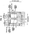
- FIG. 4 is an enlarged cross section of gaps formed in the shock absorbing unit 9 in the starter 1 according to the first embodiment.
- the shock absorbing unit 9 has a ring drive 45 as a primary case, a ring drive 46 as a secondary case, and the ring spacer 47 as an intermediate case, elastic members 48, and the like.
- the elastic members 48 are assembled between the ring drive 45 and the ring spacer 47, and between the ring spacer 47 and the ring drive 46.
- a boss part 45a of a cylindrical shape is formed at a central part in the diameter direction of the ring drive 45.
- This boss part 45a is engaged in a spline connection with the outer periphery of a cylindrical part 8a.
- This cylindrical part 8a and the pinion gear 8 are made with one body.
- the boss part 45a is so engaged with the pinion gear 8 through the cylindrical part 8a so as not to relatively rotate with the pinion gear 8.
- a boss part 46a of a cylindrical shape is formed at a central part of the ring drive 46 as the secondary case.
- the boss part 46a is engaged in a spline connection with the outer periphery of the output shaft 6.
- the boss part 46a is so engaged with the output shaft 6 so as not to relatively rotate with the output shaft 6.
- the ring spacer 47 is placed between the ring drive 45 and the ring drive 46, and is rotatably engaged with the outer periphery of the boss part 46a formed in the ring drive 46.
- a plurality of damper spaces S (see FIG. 3 ) is formed between the ring drive 45 and the ring spacer 47, and between the ring spacer 47 and the ring drive 46.
- the ring drive 45 faces the ring spacer 47 in the axial direction of the output shaft 6.
- the ring spacer 47 faces the ring drive 46 in the axial direction of the output shaft 6.
- Elastic members 48 are placed in the damper spaces S.
- FIG. 3 shows the three damper spaces S. The present invention is not limited by the number of the damper spaces S.
- the ring drives 45 and 46 are made of metal such as iron so as to obtain a desired strength for transmitting the output torque of the starter 1. On the other hand, it is possible to make the ring spacer 47 using resin in order to decrease the total weight of the starter 1.
- the elastic members 48 is comprised of a main block part 48a, a bridging part 48b, and a sub block part 48c.
- the sub block part 48c is connected to the main block part 48a through the bridging part 48b.
- the main block part 48a, the bridging part 48b, and the sub block part 48c are made with one body, and for example, made of oil-proof synthetic rubber.
- Each elastic member 48 is accommodated in each of the three damper spaces S formed between the ring drive 45 and the ring spacer 47. Each elastic member 48 is also accommodated in each of the three damper spaces S formed between the ring spacer 47 and the ring drive 46.
- Grease is applied as lubricant in the inside of the shock absorbing unit 9 so as to smoothly bend the elastic members 48 when a shock is applied to the starter 1.
- the grease is applied between the surfaces of the elastic members 48, the ring drive 45, the ring spacer 47, and the ring drive 46.
- the ring drive 45 and the ring spacer 47 which are adjacent to each other relatively and rotatably face together through the elastic members 48.
- the ring spacer 47 and the ring drive 46 are adjacent to each other, and relatively and rotatably face together through the elastic members 48.
- axial gaps A and A-1 and diameter gaps B and B-1 are formed between the outer periphery of the ring drive 45 and the outer periphery of the ring spacer 47 and between the outer periphery of the ring spacer 47 and the outer periphery of the ring drive 46.
- the axial gaps A and A-1 are formed in the axial direction of the shock absorbing unit 9 (, namely in the axial direction of the output shaft 6).
- the diameter gaps B and B-1 are formed in the diameter direction of the shock absorbing unit 9.
- the ring drive 45 has a facing-wall area
- the ring spacer 47 has a facing-wall area.
- Those facing-wall areas are formed in the diameter direction of the outside of the damper space S between the ring drive 45 and the ring spacer 47.
- Those facing-wall areas face together at a predetermined interval which will be referred to as the "gap A in the axial direction" (see the left side in FIG. 4 ).
- the gap A is formed between those facing-wall areas of the ring drive 45 and the ring spacer 47.
- An outer peripheral wall 47a of a ring shape is formed at the outer diameter part of the ring spacer 47.
- This outer peripheral wall 47a of a ring shape is extended toward the opposite side (the left side in FIG. 4 ) of the motor 2 along the axial direction from the facing-wall area. It is so formed that the inner diameter of the outer peripheral wall 47a is larger than the outer diameter of the ring drive 45 in order to form the gap B in the diameter direction (see FIG. 4 ) between the inner periphery of the outer peripheral wall 47a and the outer periphery of the ring drive 45.
- the gap A in the axial direction and the gap B in the diameter direction are connected (or communicated) together in a character "L" shape.
- the gap A and the gap B make a passage through which the grease and air flow out to the outside of the shock absorbing unit 9.
- the ring drive 46 has a facing-wall area
- the ring spacer 47 has another facing-wall area.
- Those facing-wall areas are formed in the diameter direction of the outside of the damper space S between the ring drive 46 and the ring spacer 47.
- Those facing walls face together at a predetermined interval which will be referred to as the "gap A-1 in the axial direction" (see the right side in FIG. 4 ).
- the gap A-1 is formed between those facing-wall areas of the ring drive 46 and the ring spacer 47.
- An outer peripheral wall 47a of a ring shape is formed at the outer diameter part of the ring spacer 47.
- This outer peripheral wall 47a of a ring shape is extended toward the motor side (toward the right side in FIG. 4 ) along the axial direction from the facing-wall area. It is so formed that the inner diameter of the outer peripheral wall 47a is larger than the outer diameter of the ring drive 46 in order to form the gap B-1 in the diameter direction (see FIG. 4 ) between the inner periphery of the outer peripheral wall 47a and the outer periphery of the ring drive 46.
- the gap A-1 in the axial direction and the gap B-1 in the diameter direction are connected (or communicated) in a character "L" shape. That is, the gap A-1 and the gap B-1 also make a passage through which the grease and air flow out to the outside of the shock absorbing unit 9.
- Each of the gaps A and A-1 in the axial direction has a length necessary to assemble the sealing ring 42 into the circumferential groove 44 formed in the surface of the output shaft 6 and further to assemble the pinion stopper 43 through the sealing ring 42 to the output shaft 6.
- each of the gaps B and B-1 is formed to be smaller in length than each of the gap A and A-1.
- those gaps A, A-1, B, and B-1 are formed as small as possible to be free from contacting to each other when the ring drives 45 and 46 and the ring spacer 47 relatively rotate.
- the electromagnetic relay 3 When the electromagnetic relay 3 electrically closes the main contact of the motor circuit in the motor 2 of the starter 1, the electric power is supplied from the battery to the armature 2a in the motor 2. The armature 2a thereby starts to rotate. The rotation speed of the armature 2a is reduced by the reduction device 5. The reduced rotation is transmitted to the output shaft 6. The reduced rotation is transmitted to the pinion gear 8 from the output shaft 6 through the shock absorbing unit 9. The rotation of the pinion gear 8 is transmitted to the ring gear 41 so as to crank the internal combustion engine (not shown).
- a one-way clutch incorporated in a ring gear 41 is connected to a pinion gear.
- the reversing rotation of the internal combustion engine is transmitted to the pinion gear through the ring gear.
- the starter 1 because the starter 1 according to the embodiment has the back stop clutch 4 (or the one-way clutch) capable of preventing the armature 2a from reversely rotating, it is possible to prevent the armature 2a from being in a reverse rotation even if the reverse rotation of the internal combustion engine is transmitted to the starter 1.
- the back stop clutch 4 or the one-way clutch
- the shock absorbing unit 9 is capable of absorbing a shock which is generated when the ring gear 41 attacks the pinion gear 8 during the cranking or when the internal combustion engine (not shown) reversely rotates, for example.
- the ring drive 45 and the ring drive 46 placed in the shock absorbing unit 9 relatively rotate through the ring spacer 47, and the elastic members 48 are bent (namely, are compresses and deformed) toward the circumferential direction of the starter 1.
- the torque limiter is capable of interrupting the transmission of an excessive shock by sliding the rotary disk 37 toward the direction against a friction when such an excessive shock, which could not be absorbed by the shock absorbing unit 9, is applied to the output shaft 6, where the excessive shock exceeds a predetermined torque which is set in advance (or a sliding torque of the rotary disk 37) in the torque limiter.
- the shock absorbing unit 9 in the starter 1 avoids the starter 1 from directly receiving an excessive shock transmitted through the torque transmission path, it is possible to avoid the starter 1 from a damage which would be caused by receiving an excessive shock transmitted from the internal combustion engine side.
- the shock absorbing unit 9 assembled in the starter 1 according to the embodiment of the present invention starts to rotate when the output shaft 6 rotates by receiving the rotational power of the motor 2. Accordingly, the grease applied in the inside of the shock absorbing unit 9 tends to move toward the outer periphery of the shock absorbing unit 9 by centrifugal force when the shock absorbing unit 9 rotates in synchronization with the output shaft 6.
- the gaps A and B are formed in a character "L" shape between the outer periphery of the ring drive 45 and the outer periphery of the ring spacer 47.
- the gaps A-1 and B-1 are formed in a character "L” shape between the outer periphery of the ring spacer 47 and the outer periphery of the ring drive 46, respectively, it is possible to prevent the grease from flowing out to the outside of the shock absorbing unit 9.
- the shock absorbing unit 9 has the structure in which each gap B (or B-1) measured in the diameter direction is smaller in length than each gap A (or A-1) measured in the axial direction, the shock absorbing unit 9 has a high ability of preventing the grease from being scattered to the outside.
- the structure of the shock absorbing unit 9 can keep the grease applied to the inside of the shock absorbing unit 9 for a long period of time.
- the shock absorbing unit 9 incorporated in the starter 1 according to the embodiment provides a stable shock-absorbing capability for a long period of time because the elastic members 48 are smoothly bent according to the relative rotation of the ring drive 45 and the ring drive 46 when receiving a shock transmitted from the internal combustion engine side.
- the shock absorbing unit 9 assembled in the starter 1 according to the embodiment has the gaps A and A-1 in the axial direction of the shock absorbing unit 9 between the outer periphery of the ring drive 45 and the outer periphery of the ring spacer 47 and between the outer periphery of the ring spacer 47 and the outer periphery of the ring drive 46, respectively. It is thereby possible to shift or bend the shock absorbing unit 9 by the gaps A and A-1 by pushing the ring drive 45 toward the ring drive 46 side when the sealing ring 42 is fitted into the peripheral groove 45 formed in the output shaft 6.
- the ring spacer 47 is placed between the ring drive 45 and the ring drive 46, and the six elastic members 48 are placed in double stages in series through the ring spacer 47. It is also possible to add one or more additional ring spacers and to place the elastic members 48 in not less than three stages in the ring spacers in series.
- the starter 1 has the structure in which the pinion gear 8 is always engaged with the ring gear 41.
- the present invention is not limited by this structure.
- the concept of the present invention is applied to various types of the starters, for example, to a starter in which the pinion gear is pushed toward the opposite direction of the motor in order to engage the pinion gear with the ring gear 41 when an internal combustion engine starts to operate, and the pinion gear 8 is separated from the ring gear 41 after completion of the start of the internal combustion engine.
Landscapes
- Engineering & Computer Science (AREA)
- Chemical & Material Sciences (AREA)
- Combustion & Propulsion (AREA)
- Mechanical Engineering (AREA)
- General Engineering & Computer Science (AREA)
- Connection Of Motors, Electrical Generators, Mechanical Devices, And The Like (AREA)
Claims (4)
- Démarreur (1) comprenant :un moteur (2) générant une puissance de rotation ;un arbre de sortie (6) tournant lors de la réception de la puissance de rotation transmise par le moteur (2) ;un pignon (8) qui est placé de manière à pouvoir tourner sur une périphérie extérieure de l'arbre de sortie (6) à travers un palier (7) et transmet la puissance de rotation générée par le moteur (2) à une couronne pour un moteur à combustion interne ;une unité d'absorption de choc (9) placée sur la périphérie extérieure de l'arbre de sortie (6) capable de réduire un choc appliqué depuis le moteur à combustion interne à travers le pignon (8) en compressant et en déformant les éléments élastiques (48) ;ladite unité d'absorption de choc (9) comprenant :un caisson primaire d'entraînement annulaire (45) en prise avec le pignon (8) ;un caisson secondaire d'entraînement annulaire (46) en prise avec l'arbre de sortie (6) ;un écarteur annulaire (47) ; dans lequellesdits éléments élastiques (48) sont logés dans des espaces d'amortissement (S) formés entre ledit caisson primaire d'entraînement annulaire (45) et ledit écarteur annulaire (47) et entre ledit caisson secondaire d'entraînement annulaire (46) et ledit écarteur annulaire (47), respectivement ;dans lequelledit caisson primaire d'entraînement annulaire (45) et ledit écarteur annulaire (47) présentent, dans la direction du diamètre en dehors desdits espaces d'amortissement (S), des zones de parois frontales définissant un jeu axial (A) ; etledit caisson secondaire d'entraînement annulaire (46) et ledit écarteur annulaire (47) présentent, dans la direction du diamètre en dehors desdits espaces d'amortissement (S), des zones de parois frontales définissant un autre jeu axial (A-1) ; dans lequelledit écarteur annulaire (47) présente une paroi périphérique extérieure (47a) s'étendant dans la direction axiale sur les deux côtés au-delà des zones de paroi respectives et possédant un diamètre intérieur plus grand que le diamètre extérieur du caisson primaire d'entraînement annulaire (45) et du caisson secondaire d'entraînement annulaire (46), respectivement ;de sorte qu'un jeu (B) dans la direction du diamètre soit formé entre la paroi périphérique extérieure (47a) et le caisson primaire d'entraînement annulaire (45) et qu'un autre jeu (B-1) dans la direction du diamètre soit formé entre la paroi périphérique extérieure (47a) et le caisson secondaire d'entraînement annulaire (46),ledit jeu axial (A) et ledit jeu (B) dans la direction du diamètre étant reliés l'un à l'autre dans une forme de Let ledit autre jeu axial (A-1) et ledit autre jeu (B-1) dans la direction du diamètre étant reliés l'un à l'autre dans une autre forme de L.
- Démarreur (1) selon la revendication 1, dans lequel
les éléments élastiques (48) sont assemblés en série dans des étages multiples entre le caisson primaire (45) et le caisson secondaire (46) à travers l'écarteur annulaire (47), et
le caisson primaire (45) et l'écarteur annulaire (47) sont disposés de manière relative et rotative à travers les éléments élastiques (48), et l'écarteur annulaire (47) et le caisson secondaire (46) sont disposés de manière relative et rotative à travers les éléments élastiques (48). - Démarreur (1) selon la revendication 1 ou 2, dans lequel les jeux (A, A-1) dans la direction axiale et les jeux (B, B-1) dans la direction du diamètre sont alternativement formée dans une structure de type labyrinthe.
- Démarreur (1) selon l'une quelconque des revendications 1 à 3, formé de sorte que les jeux (B et B-1) dans la direction du diamètre soient plus étroits que les jeux (A et A-1) dans la direction axiale.
Applications Claiming Priority (1)
| Application Number | Priority Date | Filing Date | Title |
|---|---|---|---|
| JP2007285123A JP2009114860A (ja) | 2007-11-01 | 2007-11-01 | スタータ |
Publications (3)
| Publication Number | Publication Date |
|---|---|
| EP2055937A2 EP2055937A2 (fr) | 2009-05-06 |
| EP2055937A3 EP2055937A3 (fr) | 2010-07-21 |
| EP2055937B1 true EP2055937B1 (fr) | 2013-12-11 |
Family
ID=40297756
Family Applications (1)
| Application Number | Title | Priority Date | Filing Date |
|---|---|---|---|
| EP08017843.7A Ceased EP2055937B1 (fr) | 2007-11-01 | 2008-10-10 | Démarreur |
Country Status (2)
| Country | Link |
|---|---|
| EP (1) | EP2055937B1 (fr) |
| JP (1) | JP2009114860A (fr) |
Families Citing this family (2)
| Publication number | Priority date | Publication date | Assignee | Title |
|---|---|---|---|---|
| DE102009045248A1 (de) * | 2009-10-01 | 2011-04-07 | Robert Bosch Gmbh | Geräuschoptimierte Startvorrichtung |
| FR2957637B1 (fr) | 2010-03-22 | 2018-10-12 | Valeo Equipements Electriques Moteur | Demarreur equipe d'un limiteur de couple associe a un pignon d'entrainement et limiteur de couple correspondant |
Family Cites Families (5)
| Publication number | Priority date | Publication date | Assignee | Title |
|---|---|---|---|---|
| US2343967A (en) * | 1943-06-19 | 1944-03-14 | Briggs & Stratton Corp | Engine starter |
| FR1245046A (fr) * | 1958-10-23 | 1960-11-04 | Bendix Aviat Corp | Lanceur réversible pour moteur à explosion ou analogue |
| JPS5820962A (ja) * | 1981-07-28 | 1983-02-07 | Hitachi Ltd | スタ−タのピニオンクラツチ機構 |
| DE102005061669B4 (de) * | 2004-12-27 | 2016-01-21 | Denso Corporation | Stoßabsorbierender Maschinenanlasser |
| JP4207026B2 (ja) * | 2004-12-27 | 2009-01-14 | 株式会社デンソー | スタータ |
-
2007
- 2007-11-01 JP JP2007285123A patent/JP2009114860A/ja active Pending
-
2008
- 2008-10-10 EP EP08017843.7A patent/EP2055937B1/fr not_active Ceased
Also Published As
| Publication number | Publication date |
|---|---|
| EP2055937A3 (fr) | 2010-07-21 |
| JP2009114860A (ja) | 2009-05-28 |
| EP2055937A2 (fr) | 2009-05-06 |
Similar Documents
| Publication | Publication Date | Title |
|---|---|---|
| JP4174820B2 (ja) | スタータ | |
| EP2006533A2 (fr) | Démarreur pour moteurs | |
| US7451668B2 (en) | Starter having excessive-torque-absorbing device | |
| US20080257077A1 (en) | Electric Starter Motor with Idle Gear | |
| US9188099B2 (en) | Starter | |
| JPH09280144A (ja) | スタータ | |
| CN103946538B (zh) | 起动器 | |
| US5740694A (en) | Starter with planetary reduction gear mechanism | |
| EP2055937A2 (fr) | Démarreur | |
| JP4487984B2 (ja) | スタータ | |
| US8272282B2 (en) | Starter motor having a shock absorber | |
| JP2009180122A (ja) | スタータ | |
| US8567364B2 (en) | Starter equipped with planetary speed reducer and shock absorber | |
| JP5941277B2 (ja) | スタータ | |
| JPH08144908A (ja) | スタータ | |
| JP2010196629A (ja) | スタータ | |
| JP4466625B2 (ja) | スタータ | |
| EP2811153A1 (fr) | Démarreur | |
| JP2008057450A (ja) | 常時噛合い式スタータ | |
| EP0742368B1 (fr) | Démarreur muni d'un dispositif empêchant le retour du pignon | |
| JP2014105640A (ja) | ダンパ内蔵ピニオン及びこのダンパ内蔵ピニオンを用いたスタータ | |
| JP2007231806A (ja) | スタータ | |
| JP4858358B2 (ja) | スタータ用緩衝装置 | |
| JP2008255949A (ja) | スタータ | |
| JP2021014808A (ja) | スタータ |
Legal Events
| Date | Code | Title | Description |
|---|---|---|---|
| PUAI | Public reference made under article 153(3) epc to a published international application that has entered the european phase |
Free format text: ORIGINAL CODE: 0009012 |
|
| AK | Designated contracting states |
Kind code of ref document: A2 Designated state(s): AT BE BG CH CY CZ DE DK EE ES FI FR GB GR HR HU IE IS IT LI LT LU LV MC MT NL NO PL PT RO SE SI SK TR |
|
| AX | Request for extension of the european patent |
Extension state: AL BA MK RS |
|
| PUAL | Search report despatched |
Free format text: ORIGINAL CODE: 0009013 |
|
| AK | Designated contracting states |
Kind code of ref document: A3 Designated state(s): AT BE BG CH CY CZ DE DK EE ES FI FR GB GR HR HU IE IS IT LI LT LU LV MC MT NL NO PL PT RO SE SI SK TR |
|
| AX | Request for extension of the european patent |
Extension state: AL BA MK RS |
|
| 17P | Request for examination filed |
Effective date: 20100810 |
|
| AKX | Designation fees paid |
Designated state(s): DE FR |
|
| 17Q | First examination report despatched |
Effective date: 20111019 |
|
| GRAP | Despatch of communication of intention to grant a patent |
Free format text: ORIGINAL CODE: EPIDOSNIGR1 |
|
| INTG | Intention to grant announced |
Effective date: 20130628 |
|
| RIN1 | Information on inventor provided before grant (corrected) |
Inventor name: OHMURA, TOMOHIRO |
|
| GRAS | Grant fee paid |
Free format text: ORIGINAL CODE: EPIDOSNIGR3 |
|
| GRAA | (expected) grant |
Free format text: ORIGINAL CODE: 0009210 |
|
| AK | Designated contracting states |
Kind code of ref document: B1 Designated state(s): DE FR |
|
| REG | Reference to a national code |
Ref country code: DE Ref legal event code: R096 Ref document number: 602008029178 Country of ref document: DE Effective date: 20140206 |
|
| REG | Reference to a national code |
Ref country code: DE Ref legal event code: R084 Ref document number: 602008029178 Country of ref document: DE Effective date: 20140526 |
|
| REG | Reference to a national code |
Ref country code: DE Ref legal event code: R097 Ref document number: 602008029178 Country of ref document: DE |
|
| PLBE | No opposition filed within time limit |
Free format text: ORIGINAL CODE: 0009261 |
|
| STAA | Information on the status of an ep patent application or granted ep patent |
Free format text: STATUS: NO OPPOSITION FILED WITHIN TIME LIMIT |
|
| 26N | No opposition filed |
Effective date: 20140912 |
|
| REG | Reference to a national code |
Ref country code: DE Ref legal event code: R097 Ref document number: 602008029178 Country of ref document: DE Effective date: 20140912 |
|
| REG | Reference to a national code |
Ref country code: FR Ref legal event code: PLFP Year of fee payment: 8 |
|
| REG | Reference to a national code |
Ref country code: FR Ref legal event code: PLFP Year of fee payment: 9 |
|
| REG | Reference to a national code |
Ref country code: FR Ref legal event code: PLFP Year of fee payment: 10 |
|
| REG | Reference to a national code |
Ref country code: FR Ref legal event code: PLFP Year of fee payment: 11 |
|
| PGFP | Annual fee paid to national office [announced via postgrant information from national office to epo] |
Ref country code: DE Payment date: 20181019 Year of fee payment: 11 |
|
| PGFP | Annual fee paid to national office [announced via postgrant information from national office to epo] |
Ref country code: FR Payment date: 20181022 Year of fee payment: 11 |
|
| REG | Reference to a national code |
Ref country code: DE Ref legal event code: R119 Ref document number: 602008029178 Country of ref document: DE |
|
| PG25 | Lapsed in a contracting state [announced via postgrant information from national office to epo] |
Ref country code: DE Free format text: LAPSE BECAUSE OF NON-PAYMENT OF DUE FEES Effective date: 20200501 |
|
| PG25 | Lapsed in a contracting state [announced via postgrant information from national office to epo] |
Ref country code: FR Free format text: LAPSE BECAUSE OF NON-PAYMENT OF DUE FEES Effective date: 20191031 |