EP2055971B1 - Radialgleitlager - Google Patents
Radialgleitlager Download PDFInfo
- Publication number
- EP2055971B1 EP2055971B1 EP07254359A EP07254359A EP2055971B1 EP 2055971 B1 EP2055971 B1 EP 2055971B1 EP 07254359 A EP07254359 A EP 07254359A EP 07254359 A EP07254359 A EP 07254359A EP 2055971 B1 EP2055971 B1 EP 2055971B1
- Authority
- EP
- European Patent Office
- Prior art keywords
- rotational part
- bearing
- assembly according
- sliding
- radial bearing
- Prior art date
- Legal status (The legal status is an assumption and is not a legal conclusion. Google has not performed a legal analysis and makes no representation as to the accuracy of the status listed.)
- Not-in-force
Links
Images
Classifications
-
- F—MECHANICAL ENGINEERING; LIGHTING; HEATING; WEAPONS; BLASTING
- F16—ENGINEERING ELEMENTS AND UNITS; GENERAL MEASURES FOR PRODUCING AND MAINTAINING EFFECTIVE FUNCTIONING OF MACHINES OR INSTALLATIONS; THERMAL INSULATION IN GENERAL
- F16C—SHAFTS; FLEXIBLE SHAFTS; ELEMENTS OR CRANKSHAFT MECHANISMS; ROTARY BODIES OTHER THAN GEARING ELEMENTS; BEARINGS
- F16C33/00—Parts of bearings; Special methods for making bearings or parts thereof
- F16C33/02—Parts of sliding-contact bearings
- F16C33/04—Brasses; Bushes; Linings
- F16C33/06—Sliding surface mainly made of metal
- F16C33/10—Construction relative to lubrication
- F16C33/1025—Construction relative to lubrication with liquid, e.g. oil, as lubricant
- F16C33/106—Details of distribution or circulation inside the bearings, e.g. details of the bearing surfaces to affect flow or pressure of the liquid
- F16C33/1085—Channels or passages to recirculate the liquid in the bearing
-
- F—MECHANICAL ENGINEERING; LIGHTING; HEATING; WEAPONS; BLASTING
- F16—ENGINEERING ELEMENTS AND UNITS; GENERAL MEASURES FOR PRODUCING AND MAINTAINING EFFECTIVE FUNCTIONING OF MACHINES OR INSTALLATIONS; THERMAL INSULATION IN GENERAL
- F16C—SHAFTS; FLEXIBLE SHAFTS; ELEMENTS OR CRANKSHAFT MECHANISMS; ROTARY BODIES OTHER THAN GEARING ELEMENTS; BEARINGS
- F16C17/00—Sliding-contact bearings for exclusively rotary movement
- F16C17/02—Sliding-contact bearings for exclusively rotary movement for radial load only
-
- F—MECHANICAL ENGINEERING; LIGHTING; HEATING; WEAPONS; BLASTING
- F16—ENGINEERING ELEMENTS AND UNITS; GENERAL MEASURES FOR PRODUCING AND MAINTAINING EFFECTIVE FUNCTIONING OF MACHINES OR INSTALLATIONS; THERMAL INSULATION IN GENERAL
- F16C—SHAFTS; FLEXIBLE SHAFTS; ELEMENTS OR CRANKSHAFT MECHANISMS; ROTARY BODIES OTHER THAN GEARING ELEMENTS; BEARINGS
- F16C35/00—Rigid support of bearing units; Housings, e.g. caps, covers
- F16C35/02—Rigid support of bearing units; Housings, e.g. caps, covers in the case of sliding-contact bearings
Definitions
- This invention relates to radial bearing assemblies for supporting rotating shafts and in particular relates to sliding bearing arrangements lubricated hydrodynamically.
- the invention relates to a bearing for use in machinery where the lubricant contains both liquid and gaseous phases in the lubricant feed.
- the lubricant which is a mixture of fluids, may, as a result of pressure or temperature change, become partially separated where some of the lubricant may change from liquid to gas either before it reaches the bearing chamber or within the chamber.
- Such bearings are likely to become damaged if a proportion of the liquid lubricant is replaced with a gaseous phase at the bearing interface, since the lubricant will have insufficient viscosity to maintain a hydrodynamic film between the stationary and moving parts of the bearing.
- a sliding radial bearing assembly to be placed about a rotating shaft in machinery where a fluid lubricant is applied to form a lubricating film between stationary and rotating parts, the assembly comprising a rotational part and a non-rotational part disposed radially outwards of the rotational part to be in sliding engagement thereon to provide a bearing interface therebetween, a casing to enclose the parts, and a lubricant passage through the casing to enable lubricant to flow through the assembly; characterised in that the lubricant passage has an outlet from the casing disposed radially inwards of the bearing interface between the rotational and non-rotational parts.
- the rotational part may be a locally enlarged diameter portion of the rotatable shaft.
- the rotational part may also be a separate annular sleeve to be mounted radially and concentrically on a rotatable shaft for rotation therewith.
- the rotational part may include at least one further passage extending axially therethrough and located radially inwards of the bearing interface between the rotational and non-rotational parts.
- the non-rotational part may be an annular bearing pad having a radially innermost bearing surface in sliding contact with the bearing surface of the rotational part.
- the non-rotational part may be an array of discrete bearing pads spaced apart circumferentially around the bearing surface of the rotational part and in sliding contact therewith.
- the lubricant passage may be formed as at least one inlet aperture and at least one outlet aperture in the casing communicating with a chamber therein containing the rotational and non-rotational parts.
- the or each further passage may be formed as an array of circumferentially spaced ducts extending axially through the rotational part.
- the or each further passage may be formed as an axial groove along the radially innermost surface of the separate annular sleeve.
- each further passage may be formed as an axial groove along the outermost surface of the shaft within the separate annular sleeve.
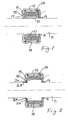
- the bearing assembly comprises a rotational part in the form of an annular sleeve 10 fixedly mounted on the surface of a shaft 11 for rotation therewith.
- a casing 12 defines an internal bearing chamber 13 containing the sleeve 10 and a non-rotational part in the form of an annular bearing pad 14 whose radially internal surface is in sliding contact with the outer bearing surface of the sleeve 10.
- An oil inlet 15 and outlet 16 provide a passage through the chamber 13 for a liquid lubricant which flows, preferably with the aid of a pump, through the chamber during rotation of the shaft 11.
- the outlet 16 is disposed radially inwards of the bearing interface between the sleeve 10 and the pad 14.
- the bearing pad 14 may, instead, comprise a circumferential array of spaced discrete pads retained by the casing 12 and each in sliding engagement with the sleeve 10.
- the lubricant at least partially separates into liquid and gaseous phases
- the liquid phase is forced radially outwards by centrifugal action, the gaseous phase is permitted to pass readily through the bearing assembly to the outlet 16 where it exits close to the shaft 11, thus avoiding the risk of gaseous content reducing the efficiency of the lubricant at the bearing interface.
- a plurality of circumferentially spaced ducts 17 extend axially through the sleeve 10 close to the shaft, ie, between the radially innermost surface of the sleeve 10 and the bearing interface between the sleeve 10 and the pad or pads 14.
- the ducts 17 are illustrated as being situated midway between the inner and outer surfaces of the sleeve 10 but ideally they should be kept as close as possible to the innermost surface and can in fact be represented as axial grooves in the innermost surface of the sleeve 10 or even as axial grooves along the outermost surface of the shaft itself.
- the ratio of the gas to liquid phases will be determined by various factors including the rate of rise of temperature from start up and so the size and location of the ducts 17 can be designed according to the operational parameters of the assembly, and these in turn may be determined by the materials used for the bearing parts.
- the materials may be metallic or in some cases ceramic or polymeric, depending on the operational environment of the machinery concerned and by the expected operating temperature within the bearing.
- the shaft 11 may be locally enlarged in diameter as shown at 20 so that the bearing interface is disposed radially outwards of the outlet aperture 16, and so for this purpose the casing 12 extends inwards to a position closely adjacent the normal (non-enlarged) diameter of the shaft 11.
- the outlet 16 provides an annular gap between the casing and the lesser diameter of the shaft.
- the enlarged diameter portion 20 may include axial ducts similar to ducts 17 in Fig. 1 . If no axial ducts are provided then the gas will exit through a gap 16A whilst the lubricant that has passed through the bearing will exit through the outlet 16.
- the outlet 16 may be of a radially larger diameter than the gap 16A.
- the arrangement of Fig. 2 may be more convenient and less costly in an application where the bearing assembly and shaft are fabricated as part of the same manufacturing process, whereas the arrangement illustrated in Fig. 1 may be more convenient where the bearing assembly is manufactured separately and subsequently applied to an existing shaft.
Landscapes
- Engineering & Computer Science (AREA)
- General Engineering & Computer Science (AREA)
- Mechanical Engineering (AREA)
- Chemical & Material Sciences (AREA)
- Oil, Petroleum & Natural Gas (AREA)
- Sliding-Contact Bearings (AREA)
Claims (9)
- Radialgleitlager-Aufbau, der um eine drehende Welle (11) herum in einer Maschinenanlage platziert werden soll, wobei ein Fluidschmiermittel aufgebracht ist, um einen Schmierfilm zwischen stationären und rotierenden Teilen zu bilden, wobei der Aufbau einen rotierenden Teil (10, 20) und einen nicht rotierenden Teil (14), der radial auswärts des rotierenden Teils (10, 20) angeordnet ist, um in gleitendem Eingriff damit zu stehen, um eine Lagerübergangsstelle dazwischen zu bilden, ein Gehäuse (12), um die Teile zu umgeben, und einen Schmiermitteldurchgang durch das Gehäuse (12) umfasst, um es zu ermöglichen, dass Schmiermittel durch den Aufbau fließt, wobei der Schmiermitteldurchgang einen Auslass (16) aus dem Gehäuse (12) aufweist, der radial einwärts der Lagerübergangsstelle zwischen dem rotierenden Teil (10, 20) und dem nicht rotierenden Teil (14) angeordnet ist.
- Radialgleitlager-Aufbau nach Anspruch 1, wenn auf einer rotierbaren Welle (11) angebracht, wobei der rotierende Teil ein Abschnitt (20) der rotierbaren Welle (11) mit einem lokal vergrößerten Durchmesser ist.
- Radialgleitlager-Aufbau nach Anspruch 1, wobei der rotierende Teil eine separate ringförmige Hülse (10) ist, die radial und konzentrisch auf einer rotierbaren Welle (11) für eine Rotation damit angebracht ist.
- Radialgleitlager-Aufbau nach einem der vorhergehenden Ansprüche, mindestens einen weiteren Durchgang (17) einschließend, der sich axial durch den rotierenden Teil (10, 20) erstreckt und sich radial einwärts der Lagerübergangsstelle zwischen dem rotierenden Teil (10, 20) und dem nicht rotierenden Teil (14) befindet.
- Radialgleitlager-Aufbau nach einem der vorhergehenden Ansprüche, wobei der nicht rotierende Teil (14) eine ringförmige Lagerplatte ist, die eine radial innerste Lagerfläche in gleitendem Kontakt mit der Lagerfläche des rotierenden Teils (10, 20) aufweist.
- Radialgleitlager-Aufbau nach einem der Ansprüche 1 bis 4, wobei der nicht rotierende Teil (14) eine Anordnung von diskreten Lagerplatten ist, die sich umfänglich beabstandet um die Lagerfläche des rotierenden Teils (10, 20) herum und in gleitendem Kontakt damit befinden.
- Radialgleitlager-Aufbau nach Anspruch 4, wobei der oder jeder weitere Durchgang (17) als eine Anordnung von umfänglich beabstandeten Kanälen gebildet ist, die sich axial durch den rotierenden Teil (10, 20) erstrecken.
- Radialgleitlager-Aufbau nach Anspruch 1, wobei der rotierende Teil eine separate ringförmige Hülse (10) ist, die radial und konzentrisch auf einer rotierbaren Welle (11) für eine Rotation damit anzubringen ist, und wobei mindestens ein weiterer Durchgang radial einwärts der Lagerübergangsstelle zwischen dem rotierenden Teil (10) und dem nicht rotierenden Teil (14) vorgesehen ist, wobei der oder jeder weitere Durchgang als eine axiale Rille entlang der radial innersten Fläche der separaten ringförmigen Hülse gebildet ist.
- Radialgleitlager-Aufbau nach Anspruch 1, wenn auf einer rotierbaren Welle (11) angebracht, wobei der rotierende Teil eine separate ringförmige Hülse (10) ist, die radial und konzentrisch auf der rotierbaren Welle (11) für eine Rotation damit angebracht ist, und wobei mindestens ein weiterer Durchgang radial einwärts der Lagerübergangsstelle zwischen dem rotierenden Teil (10) und dem nicht rotierenden Teil (14) vorgesehen ist, wobei der oder jeder weitere Durchgang als eine axiale Rille entlang der radial äußersten Fläche der Welle (11) innerhalb des Aufbaus gebildet ist.
Priority Applications (3)
| Application Number | Priority Date | Filing Date | Title |
|---|---|---|---|
| EP07254359A EP2055971B1 (de) | 2007-11-03 | 2007-11-03 | Radialgleitlager |
| NO20084514A NO20084514L (no) | 2007-11-03 | 2008-10-27 | Glideradiallager |
| US12/290,327 US8070362B2 (en) | 2007-11-03 | 2008-10-29 | Sliding radial bearing |
Applications Claiming Priority (1)
| Application Number | Priority Date | Filing Date | Title |
|---|---|---|---|
| EP07254359A EP2055971B1 (de) | 2007-11-03 | 2007-11-03 | Radialgleitlager |
Publications (2)
| Publication Number | Publication Date |
|---|---|
| EP2055971A1 EP2055971A1 (de) | 2009-05-06 |
| EP2055971B1 true EP2055971B1 (de) | 2012-08-08 |
Family
ID=39467258
Family Applications (1)
| Application Number | Title | Priority Date | Filing Date |
|---|---|---|---|
| EP07254359A Not-in-force EP2055971B1 (de) | 2007-11-03 | 2007-11-03 | Radialgleitlager |
Country Status (3)
| Country | Link |
|---|---|
| US (1) | US8070362B2 (de) |
| EP (1) | EP2055971B1 (de) |
| NO (1) | NO20084514L (de) |
Families Citing this family (2)
| Publication number | Priority date | Publication date | Assignee | Title |
|---|---|---|---|---|
| US9581199B2 (en) * | 2012-10-25 | 2017-02-28 | Ntn Corporation | Fulcrum bearing device for pulley arm |
| ITUB20153896A1 (it) * | 2015-09-25 | 2017-03-25 | Nuovo Pignone Tecnologie Srl | Metodo per uniformare la temperatura in un albero supportato da un cuscinetto a fluido, sistema a cuscinetto e turbomacchina |
Family Cites Families (5)
| Publication number | Priority date | Publication date | Assignee | Title |
|---|---|---|---|---|
| JP3206191B2 (ja) * | 1993-03-15 | 2001-09-04 | 松下電器産業株式会社 | スピンドルモータおよびその組立方法 |
| GB2278160A (en) * | 1993-05-05 | 1994-11-23 | G L Jones Engineering Limited | A bearing for a swing |
| US5524728A (en) * | 1995-06-28 | 1996-06-11 | Quantum Corporation | Method and apparatus for applying lubricant to a hydrodynamic bearing |
| US6361214B1 (en) * | 1999-08-02 | 2002-03-26 | Nidec Corporation | Hydrodynamic-pressure bearing device and motor provided with the hydrodynamic-pressure bearing device |
| GB2409008A (en) * | 2003-12-10 | 2005-06-15 | Echlin Do Brasil Ind E Com Ltd | A hydrodynamic bearing arrangement for a rotatable shaft |
-
2007
- 2007-11-03 EP EP07254359A patent/EP2055971B1/de not_active Not-in-force
-
2008
- 2008-10-27 NO NO20084514A patent/NO20084514L/no not_active Application Discontinuation
- 2008-10-29 US US12/290,327 patent/US8070362B2/en not_active Expired - Fee Related
Also Published As
| Publication number | Publication date |
|---|---|
| EP2055971A1 (de) | 2009-05-06 |
| NO20084514L (no) | 2009-05-04 |
| US20090116769A1 (en) | 2009-05-07 |
| US8070362B2 (en) | 2011-12-06 |
Similar Documents
| Publication | Publication Date | Title |
|---|---|---|
| KR102276083B1 (ko) | 슬라이딩 부품 | |
| KR102276081B1 (ko) | 슬라이딩 부품 | |
| JP7098260B2 (ja) | 摺動部品 | |
| EP3540274B1 (de) | Gleitkomponente | |
| CA2699711C (en) | Hydrodynamic axial bearing | |
| KR101027459B1 (ko) | 축방향 마찰 베어링 | |
| WO2016186019A1 (ja) | 摺動部品 | |
| EP3208501B1 (de) | Dichtungsvorrichtung | |
| CN103842667A (zh) | 增压器的止推轴承装置 | |
| US8882356B2 (en) | Horizontal shaft type rotary machine | |
| EP3627012B1 (de) | Gleitkomponente | |
| US8070362B2 (en) | Sliding radial bearing | |
| US9133939B2 (en) | Seal | |
| EP2602440A2 (de) | Lageranordnung | |
| KR101998010B1 (ko) | 디스크 스택 원심 분리기 | |
| JP4442461B2 (ja) | 液体潤滑フォイル式動圧軸受 | |
| JP2018115706A (ja) | スリーブ、前記スリーブを備えた軸封装置および前記軸封装置を備えたポンプならびにスリーブの主軸に対する相対回転を防止する方法 | |
| JP6921060B2 (ja) | 流体軸受によって支持されたシャフトの温度を均一化するための方法、軸受システム、およびターボ機械 | |
| RU34226U1 (ru) | Опора качения | |
| RU2186266C2 (ru) | Опорно-упорный подшипник скольжения, работающий на маловязкой жидкости | |
| CN112867870A (zh) | 用于轴稳定的多轴承设计 | |
| JPS6110112A (ja) | 水中軸受装置 |
Legal Events
| Date | Code | Title | Description |
|---|---|---|---|
| PUAI | Public reference made under article 153(3) epc to a published international application that has entered the european phase |
Free format text: ORIGINAL CODE: 0009012 |
|
| AK | Designated contracting states |
Kind code of ref document: A1 Designated state(s): AT BE BG CH CY CZ DE DK EE ES FI FR GB GR HU IE IS IT LI LT LU LV MC MT NL PL PT RO SE SI SK TR |
|
| AX | Request for extension of the european patent |
Extension state: AL BA HR MK RS |
|
| 17P | Request for examination filed |
Effective date: 20090601 |
|
| 17Q | First examination report despatched |
Effective date: 20090715 |
|
| AKX | Designation fees paid |
Designated state(s): AT BE BG CH CY CZ DE DK EE ES FI FR GB GR HU IE IS IT LI LT LU LV MC MT NL PL PT RO SE SI SK TR |
|
| GRAP | Despatch of communication of intention to grant a patent |
Free format text: ORIGINAL CODE: EPIDOSNIGR1 |
|
| GRAS | Grant fee paid |
Free format text: ORIGINAL CODE: EPIDOSNIGR3 |
|
| GRAA | (expected) grant |
Free format text: ORIGINAL CODE: 0009210 |
|
| AK | Designated contracting states |
Kind code of ref document: B1 Designated state(s): AT BE BG CH CY CZ DE DK EE ES FI FR GB GR HU IE IS IT LI LT LU LV MC MT NL PL PT RO SE SI SK TR |
|
| REG | Reference to a national code |
Ref country code: GB Ref legal event code: FG4D |
|
| REG | Reference to a national code |
Ref country code: AT Ref legal event code: REF Ref document number: 569935 Country of ref document: AT Kind code of ref document: T Effective date: 20120815 Ref country code: CH Ref legal event code: EP |
|
| REG | Reference to a national code |
Ref country code: IE Ref legal event code: FG4D |
|
| REG | Reference to a national code |
Ref country code: DE Ref legal event code: R096 Ref document number: 602007024531 Country of ref document: DE Effective date: 20121004 |
|
| REG | Reference to a national code |
Ref country code: NL Ref legal event code: VDEP Effective date: 20120808 |
|
| REG | Reference to a national code |
Ref country code: AT Ref legal event code: MK05 Ref document number: 569935 Country of ref document: AT Kind code of ref document: T Effective date: 20120808 |
|
| REG | Reference to a national code |
Ref country code: LT Ref legal event code: MG4D Effective date: 20120808 |
|
| PG25 | Lapsed in a contracting state [announced via postgrant information from national office to epo] |
Ref country code: LT Free format text: LAPSE BECAUSE OF FAILURE TO SUBMIT A TRANSLATION OF THE DESCRIPTION OR TO PAY THE FEE WITHIN THE PRESCRIBED TIME-LIMIT Effective date: 20120808 Ref country code: AT Free format text: LAPSE BECAUSE OF FAILURE TO SUBMIT A TRANSLATION OF THE DESCRIPTION OR TO PAY THE FEE WITHIN THE PRESCRIBED TIME-LIMIT Effective date: 20120808 Ref country code: IS Free format text: LAPSE BECAUSE OF FAILURE TO SUBMIT A TRANSLATION OF THE DESCRIPTION OR TO PAY THE FEE WITHIN THE PRESCRIBED TIME-LIMIT Effective date: 20121208 Ref country code: FI Free format text: LAPSE BECAUSE OF FAILURE TO SUBMIT A TRANSLATION OF THE DESCRIPTION OR TO PAY THE FEE WITHIN THE PRESCRIBED TIME-LIMIT Effective date: 20120808 Ref country code: CY Free format text: LAPSE BECAUSE OF FAILURE TO SUBMIT A TRANSLATION OF THE DESCRIPTION OR TO PAY THE FEE WITHIN THE PRESCRIBED TIME-LIMIT Effective date: 20120808 |
|
| PG25 | Lapsed in a contracting state [announced via postgrant information from national office to epo] |
Ref country code: PL Free format text: LAPSE BECAUSE OF FAILURE TO SUBMIT A TRANSLATION OF THE DESCRIPTION OR TO PAY THE FEE WITHIN THE PRESCRIBED TIME-LIMIT Effective date: 20120808 Ref country code: LV Free format text: LAPSE BECAUSE OF FAILURE TO SUBMIT A TRANSLATION OF THE DESCRIPTION OR TO PAY THE FEE WITHIN THE PRESCRIBED TIME-LIMIT Effective date: 20120808 Ref country code: BE Free format text: LAPSE BECAUSE OF FAILURE TO SUBMIT A TRANSLATION OF THE DESCRIPTION OR TO PAY THE FEE WITHIN THE PRESCRIBED TIME-LIMIT Effective date: 20120808 Ref country code: GR Free format text: LAPSE BECAUSE OF FAILURE TO SUBMIT A TRANSLATION OF THE DESCRIPTION OR TO PAY THE FEE WITHIN THE PRESCRIBED TIME-LIMIT Effective date: 20121109 Ref country code: SE Free format text: LAPSE BECAUSE OF FAILURE TO SUBMIT A TRANSLATION OF THE DESCRIPTION OR TO PAY THE FEE WITHIN THE PRESCRIBED TIME-LIMIT Effective date: 20120808 Ref country code: SI Free format text: LAPSE BECAUSE OF FAILURE TO SUBMIT A TRANSLATION OF THE DESCRIPTION OR TO PAY THE FEE WITHIN THE PRESCRIBED TIME-LIMIT Effective date: 20120808 Ref country code: PT Free format text: LAPSE BECAUSE OF FAILURE TO SUBMIT A TRANSLATION OF THE DESCRIPTION OR TO PAY THE FEE WITHIN THE PRESCRIBED TIME-LIMIT Effective date: 20121210 |
|
| PG25 | Lapsed in a contracting state [announced via postgrant information from national office to epo] |
Ref country code: NL Free format text: LAPSE BECAUSE OF FAILURE TO SUBMIT A TRANSLATION OF THE DESCRIPTION OR TO PAY THE FEE WITHIN THE PRESCRIBED TIME-LIMIT Effective date: 20120808 |
|
| PG25 | Lapsed in a contracting state [announced via postgrant information from national office to epo] |
Ref country code: DK Free format text: LAPSE BECAUSE OF FAILURE TO SUBMIT A TRANSLATION OF THE DESCRIPTION OR TO PAY THE FEE WITHIN THE PRESCRIBED TIME-LIMIT Effective date: 20120808 Ref country code: RO Free format text: LAPSE BECAUSE OF FAILURE TO SUBMIT A TRANSLATION OF THE DESCRIPTION OR TO PAY THE FEE WITHIN THE PRESCRIBED TIME-LIMIT Effective date: 20120808 Ref country code: ES Free format text: LAPSE BECAUSE OF FAILURE TO SUBMIT A TRANSLATION OF THE DESCRIPTION OR TO PAY THE FEE WITHIN THE PRESCRIBED TIME-LIMIT Effective date: 20121119 Ref country code: EE Free format text: LAPSE BECAUSE OF FAILURE TO SUBMIT A TRANSLATION OF THE DESCRIPTION OR TO PAY THE FEE WITHIN THE PRESCRIBED TIME-LIMIT Effective date: 20120808 Ref country code: CZ Free format text: LAPSE BECAUSE OF FAILURE TO SUBMIT A TRANSLATION OF THE DESCRIPTION OR TO PAY THE FEE WITHIN THE PRESCRIBED TIME-LIMIT Effective date: 20120808 |
|
| PG25 | Lapsed in a contracting state [announced via postgrant information from national office to epo] |
Ref country code: SK Free format text: LAPSE BECAUSE OF FAILURE TO SUBMIT A TRANSLATION OF THE DESCRIPTION OR TO PAY THE FEE WITHIN THE PRESCRIBED TIME-LIMIT Effective date: 20120808 |
|
| PLBE | No opposition filed within time limit |
Free format text: ORIGINAL CODE: 0009261 |
|
| STAA | Information on the status of an ep patent application or granted ep patent |
Free format text: STATUS: NO OPPOSITION FILED WITHIN TIME LIMIT |
|
| REG | Reference to a national code |
Ref country code: CH Ref legal event code: PL |
|
| 26N | No opposition filed |
Effective date: 20130510 |
|
| PG25 | Lapsed in a contracting state [announced via postgrant information from national office to epo] |
Ref country code: CH Free format text: LAPSE BECAUSE OF NON-PAYMENT OF DUE FEES Effective date: 20121130 Ref country code: LI Free format text: LAPSE BECAUSE OF NON-PAYMENT OF DUE FEES Effective date: 20121130 Ref country code: BG Free format text: LAPSE BECAUSE OF FAILURE TO SUBMIT A TRANSLATION OF THE DESCRIPTION OR TO PAY THE FEE WITHIN THE PRESCRIBED TIME-LIMIT Effective date: 20121108 |
|
| REG | Reference to a national code |
Ref country code: IE Ref legal event code: MM4A |
|
| REG | Reference to a national code |
Ref country code: FR Ref legal event code: ST Effective date: 20130731 |
|
| REG | Reference to a national code |
Ref country code: DE Ref legal event code: R097 Ref document number: 602007024531 Country of ref document: DE Effective date: 20130510 |
|
| REG | Reference to a national code |
Ref country code: DE Ref legal event code: R119 Ref document number: 602007024531 Country of ref document: DE Effective date: 20130601 |
|
| PG25 | Lapsed in a contracting state [announced via postgrant information from national office to epo] |
Ref country code: IE Free format text: LAPSE BECAUSE OF NON-PAYMENT OF DUE FEES Effective date: 20121103 Ref country code: DE Free format text: LAPSE BECAUSE OF NON-PAYMENT OF DUE FEES Effective date: 20130601 |
|
| PG25 | Lapsed in a contracting state [announced via postgrant information from national office to epo] |
Ref country code: FR Free format text: LAPSE BECAUSE OF NON-PAYMENT OF DUE FEES Effective date: 20121130 Ref country code: MT Free format text: LAPSE BECAUSE OF FAILURE TO SUBMIT A TRANSLATION OF THE DESCRIPTION OR TO PAY THE FEE WITHIN THE PRESCRIBED TIME-LIMIT Effective date: 20120808 |
|
| PG25 | Lapsed in a contracting state [announced via postgrant information from national office to epo] |
Ref country code: MC Free format text: LAPSE BECAUSE OF NON-PAYMENT OF DUE FEES Effective date: 20121130 Ref country code: TR Free format text: LAPSE BECAUSE OF FAILURE TO SUBMIT A TRANSLATION OF THE DESCRIPTION OR TO PAY THE FEE WITHIN THE PRESCRIBED TIME-LIMIT Effective date: 20120808 |
|
| PG25 | Lapsed in a contracting state [announced via postgrant information from national office to epo] |
Ref country code: LU Free format text: LAPSE BECAUSE OF NON-PAYMENT OF DUE FEES Effective date: 20121103 |
|
| PG25 | Lapsed in a contracting state [announced via postgrant information from national office to epo] |
Ref country code: HU Free format text: LAPSE BECAUSE OF FAILURE TO SUBMIT A TRANSLATION OF THE DESCRIPTION OR TO PAY THE FEE WITHIN THE PRESCRIBED TIME-LIMIT Effective date: 20071103 |
|
| PGFP | Annual fee paid to national office [announced via postgrant information from national office to epo] |
Ref country code: GB Payment date: 20180904 Year of fee payment: 12 |
|
| PGFP | Annual fee paid to national office [announced via postgrant information from national office to epo] |
Ref country code: IT Payment date: 20181106 Year of fee payment: 12 |
|
| GBPC | Gb: european patent ceased through non-payment of renewal fee |
Effective date: 20191103 |
|
| PG25 | Lapsed in a contracting state [announced via postgrant information from national office to epo] |
Ref country code: IT Free format text: LAPSE BECAUSE OF NON-PAYMENT OF DUE FEES Effective date: 20191103 Ref country code: GB Free format text: LAPSE BECAUSE OF NON-PAYMENT OF DUE FEES Effective date: 20191103 |