EP2055972A2 - Lageranordnung mit zwei geschmierten Wälzlagern zur Lagerung einer Ritzelwelle - Google Patents
Lageranordnung mit zwei geschmierten Wälzlagern zur Lagerung einer Ritzelwelle Download PDFInfo
- Publication number
- EP2055972A2 EP2055972A2 EP08018984A EP08018984A EP2055972A2 EP 2055972 A2 EP2055972 A2 EP 2055972A2 EP 08018984 A EP08018984 A EP 08018984A EP 08018984 A EP08018984 A EP 08018984A EP 2055972 A2 EP2055972 A2 EP 2055972A2
- Authority
- EP
- European Patent Office
- Prior art keywords
- tapered roller
- forming member
- labyrinth
- roller bearing
- face
- Prior art date
- Legal status (The legal status is an assumption and is not a legal conclusion. Google has not performed a legal analysis and makes no representation as to the accuracy of the status listed.)
- Withdrawn
Links
- 238000005096 rolling process Methods 0.000 title claims description 24
- 239000010687 lubricating oil Substances 0.000 claims abstract description 37
- 238000000034 method Methods 0.000 claims abstract description 8
- 238000005461 lubrication Methods 0.000 claims abstract description 7
- 239000003921 oil Substances 0.000 claims abstract description 7
- 125000006850 spacer group Chemical group 0.000 claims description 23
- 238000004519 manufacturing process Methods 0.000 description 7
- 230000001050 lubricating effect Effects 0.000 description 6
- 230000004048 modification Effects 0.000 description 5
- 238000012986 modification Methods 0.000 description 5
- 230000002093 peripheral effect Effects 0.000 description 5
- 239000000470 constituent Substances 0.000 description 3
- 230000000994 depressogenic effect Effects 0.000 description 3
- 230000036316 preload Effects 0.000 description 3
- 230000009467 reduction Effects 0.000 description 2
- 238000003756 stirring Methods 0.000 description 2
- 238000005299 abrasion Methods 0.000 description 1
- 230000009471 action Effects 0.000 description 1
- 238000005452 bending Methods 0.000 description 1
- 238000012423 maintenance Methods 0.000 description 1
- 239000000843 powder Substances 0.000 description 1
- 230000001105 regulatory effect Effects 0.000 description 1
- 230000000717 retained effect Effects 0.000 description 1
- 238000007789 sealing Methods 0.000 description 1
- 238000003892 spreading Methods 0.000 description 1
- 230000007480 spreading Effects 0.000 description 1
Images

Classifications
-
- F—MECHANICAL ENGINEERING; LIGHTING; HEATING; WEAPONS; BLASTING
- F16—ENGINEERING ELEMENTS AND UNITS; GENERAL MEASURES FOR PRODUCING AND MAINTAINING EFFECTIVE FUNCTIONING OF MACHINES OR INSTALLATIONS; THERMAL INSULATION IN GENERAL
- F16C—SHAFTS; FLEXIBLE SHAFTS; ELEMENTS OR CRANKSHAFT MECHANISMS; ROTARY BODIES OTHER THAN GEARING ELEMENTS; BEARINGS
- F16C19/00—Bearings with rolling contact, for exclusively rotary movement
- F16C19/54—Systems consisting of a plurality of bearings with rolling friction
-
- F—MECHANICAL ENGINEERING; LIGHTING; HEATING; WEAPONS; BLASTING
- F16—ENGINEERING ELEMENTS AND UNITS; GENERAL MEASURES FOR PRODUCING AND MAINTAINING EFFECTIVE FUNCTIONING OF MACHINES OR INSTALLATIONS; THERMAL INSULATION IN GENERAL
- F16C—SHAFTS; FLEXIBLE SHAFTS; ELEMENTS OR CRANKSHAFT MECHANISMS; ROTARY BODIES OTHER THAN GEARING ELEMENTS; BEARINGS
- F16C19/00—Bearings with rolling contact, for exclusively rotary movement
- F16C19/22—Bearings with rolling contact, for exclusively rotary movement with bearing rollers essentially of the same size in one or more circular rows, e.g. needle bearings
- F16C19/34—Bearings with rolling contact, for exclusively rotary movement with bearing rollers essentially of the same size in one or more circular rows, e.g. needle bearings for both radial and axial load
- F16C19/36—Bearings with rolling contact, for exclusively rotary movement with bearing rollers essentially of the same size in one or more circular rows, e.g. needle bearings for both radial and axial load with a single row of rollers
- F16C19/364—Bearings with rolling contact, for exclusively rotary movement with bearing rollers essentially of the same size in one or more circular rows, e.g. needle bearings for both radial and axial load with a single row of rollers with tapered rollers, i.e. rollers having essentially the shape of a truncated cone
-
- F—MECHANICAL ENGINEERING; LIGHTING; HEATING; WEAPONS; BLASTING
- F16—ENGINEERING ELEMENTS AND UNITS; GENERAL MEASURES FOR PRODUCING AND MAINTAINING EFFECTIVE FUNCTIONING OF MACHINES OR INSTALLATIONS; THERMAL INSULATION IN GENERAL
- F16C—SHAFTS; FLEXIBLE SHAFTS; ELEMENTS OR CRANKSHAFT MECHANISMS; ROTARY BODIES OTHER THAN GEARING ELEMENTS; BEARINGS
- F16C19/00—Bearings with rolling contact, for exclusively rotary movement
- F16C19/54—Systems consisting of a plurality of bearings with rolling friction
- F16C19/546—Systems with spaced apart rolling bearings including at least one angular contact bearing
- F16C19/547—Systems with spaced apart rolling bearings including at least one angular contact bearing with two angular contact rolling bearings
- F16C19/548—Systems with spaced apart rolling bearings including at least one angular contact bearing with two angular contact rolling bearings in O-arrangement
-
- F—MECHANICAL ENGINEERING; LIGHTING; HEATING; WEAPONS; BLASTING
- F16—ENGINEERING ELEMENTS AND UNITS; GENERAL MEASURES FOR PRODUCING AND MAINTAINING EFFECTIVE FUNCTIONING OF MACHINES OR INSTALLATIONS; THERMAL INSULATION IN GENERAL
- F16C—SHAFTS; FLEXIBLE SHAFTS; ELEMENTS OR CRANKSHAFT MECHANISMS; ROTARY BODIES OTHER THAN GEARING ELEMENTS; BEARINGS
- F16C25/00—Bearings for exclusively rotary movement adjustable for wear or play
- F16C25/06—Ball or roller bearings
- F16C25/08—Ball or roller bearings self-adjusting
- F16C25/083—Ball or roller bearings self-adjusting with resilient means acting axially on a race ring to preload the bearing
-
- F—MECHANICAL ENGINEERING; LIGHTING; HEATING; WEAPONS; BLASTING
- F16—ENGINEERING ELEMENTS AND UNITS; GENERAL MEASURES FOR PRODUCING AND MAINTAINING EFFECTIVE FUNCTIONING OF MACHINES OR INSTALLATIONS; THERMAL INSULATION IN GENERAL
- F16C—SHAFTS; FLEXIBLE SHAFTS; ELEMENTS OR CRANKSHAFT MECHANISMS; ROTARY BODIES OTHER THAN GEARING ELEMENTS; BEARINGS
- F16C33/00—Parts of bearings; Special methods for making bearings or parts thereof
- F16C33/30—Parts of ball or roller bearings
- F16C33/46—Cages for rollers or needles
-
- F—MECHANICAL ENGINEERING; LIGHTING; HEATING; WEAPONS; BLASTING
- F16—ENGINEERING ELEMENTS AND UNITS; GENERAL MEASURES FOR PRODUCING AND MAINTAINING EFFECTIVE FUNCTIONING OF MACHINES OR INSTALLATIONS; THERMAL INSULATION IN GENERAL
- F16C—SHAFTS; FLEXIBLE SHAFTS; ELEMENTS OR CRANKSHAFT MECHANISMS; ROTARY BODIES OTHER THAN GEARING ELEMENTS; BEARINGS
- F16C33/00—Parts of bearings; Special methods for making bearings or parts thereof
- F16C33/30—Parts of ball or roller bearings
- F16C33/66—Special parts or details in view of lubrication
- F16C33/6637—Special parts or details in view of lubrication with liquid lubricant
- F16C33/6659—Details of supply of the liquid to the bearing, e.g. passages or nozzles
- F16C33/6674—Details of supply of the liquid to the bearing, e.g. passages or nozzles related to the amount supplied, e.g. gaps to restrict flow of the liquid
-
- F—MECHANICAL ENGINEERING; LIGHTING; HEATING; WEAPONS; BLASTING
- F16—ENGINEERING ELEMENTS AND UNITS; GENERAL MEASURES FOR PRODUCING AND MAINTAINING EFFECTIVE FUNCTIONING OF MACHINES OR INSTALLATIONS; THERMAL INSULATION IN GENERAL
- F16H—GEARING
- F16H57/00—General details of gearing
- F16H57/02—Gearboxes; Mounting gearing therein
- F16H57/037—Gearboxes for accommodating differential gearings
-
- F—MECHANICAL ENGINEERING; LIGHTING; HEATING; WEAPONS; BLASTING
- F16—ENGINEERING ELEMENTS AND UNITS; GENERAL MEASURES FOR PRODUCING AND MAINTAINING EFFECTIVE FUNCTIONING OF MACHINES OR INSTALLATIONS; THERMAL INSULATION IN GENERAL
- F16H—GEARING
- F16H57/00—General details of gearing
- F16H57/04—Features relating to lubrication or cooling or heating
- F16H57/048—Type of gearings to be lubricated, cooled or heated
- F16H57/0482—Gearings with gears having orbital motion
- F16H57/0483—Axle or inter-axle differentials
-
- F—MECHANICAL ENGINEERING; LIGHTING; HEATING; WEAPONS; BLASTING
- F16—ENGINEERING ELEMENTS AND UNITS; GENERAL MEASURES FOR PRODUCING AND MAINTAINING EFFECTIVE FUNCTIONING OF MACHINES OR INSTALLATIONS; THERMAL INSULATION IN GENERAL
- F16C—SHAFTS; FLEXIBLE SHAFTS; ELEMENTS OR CRANKSHAFT MECHANISMS; ROTARY BODIES OTHER THAN GEARING ELEMENTS; BEARINGS
- F16C2361/00—Apparatus or articles in engineering in general
- F16C2361/61—Toothed gear systems, e.g. support of pinion shafts
-
- F—MECHANICAL ENGINEERING; LIGHTING; HEATING; WEAPONS; BLASTING
- F16—ENGINEERING ELEMENTS AND UNITS; GENERAL MEASURES FOR PRODUCING AND MAINTAINING EFFECTIVE FUNCTIONING OF MACHINES OR INSTALLATIONS; THERMAL INSULATION IN GENERAL
- F16H—GEARING
- F16H48/00—Differential gearings
- F16H48/38—Constructional details
- F16H48/42—Constructional details characterised by features of the input shafts, e.g. mounting of drive gears thereon
- F16H2048/423—Constructional details characterised by features of the input shafts, e.g. mounting of drive gears thereon characterised by bearing arrangement
- F16H2048/426—Constructional details characterised by features of the input shafts, e.g. mounting of drive gears thereon characterised by bearing arrangement characterised by spigot bearing arrangement, e.g. bearing for supporting the free end of the drive shaft pinion
-
- F—MECHANICAL ENGINEERING; LIGHTING; HEATING; WEAPONS; BLASTING
- F16—ENGINEERING ELEMENTS AND UNITS; GENERAL MEASURES FOR PRODUCING AND MAINTAINING EFFECTIVE FUNCTIONING OF MACHINES OR INSTALLATIONS; THERMAL INSULATION IN GENERAL
- F16H—GEARING
- F16H57/00—General details of gearing
- F16H57/04—Features relating to lubrication or cooling or heating
- F16H57/0467—Elements of gearings to be lubricated, cooled or heated
- F16H57/0469—Bearings or seals
- F16H57/0471—Bearing
Definitions
- the present invention relates to a bearing apparatus for supporting a pinion shaft, and more particularly, to the bearing apparatus for supporting the pinion shaft which is provided in a differential gear of a vehicle such as an automobile.
- a differential gear mounted on a vehicle such as an automobile is provided with a supporting device for a pinion shaft which has a pinion gear formed at its one end, for enabling the pinion gear to be meshed with a ring gear which constitute a final reduction unit.
- the bearing apparatus for supporting the pinion shaft is so constructed that the pinion shaft is supported in a housing by means of two rolling bearings of angular contact type.
- the rolling bearings of the angular contact type tapered roller bearings are employed for general purpose. Two tapered roller bearings are held inside the housing separately from each other in an axial direction and in back to back arrangement, and a spacer in a cylindrical shape is interposed between respective inner rings of the two bearings which are arranged separately.
- the tapered roller bearing has relatively large rotation resistance, because tapered rollers have large contact areas with respect to an outer ring and an inner ring, and a slid occurs with respect to a large rib portion of the inner ring.
- This tapered roller bearing is lubricated in an oil bath lubrication method in which lubricating oil inside the housing is passed through the tapered roller bearing. Therefore, in case where an excessive amount of the lubricating oil flows into the bearing, stirring resistance: of the lubricating oil is increased, which results in an increase of the rotation resistance. Moreover, abrasion powder from gears which is contained in the lubricating oil may enter into the bearing, and hence, the tapered rollers, the inner and outer rings are likely to be damaged.
- JP-A-2005-273796 there is disclosed such a structure that a cage of a tapered roller bearing is made larger than a virtual conical plane which is formed by tying respective rotation axes of tapered rollers, and a rib part directed inwardly in a radial direction is formed at a small diameter side end of this cage, an inner diameter of this rib part being made smaller than an outer diameter of the inner ring, and this rib part is arranged so as to be opposed to a front face of the inner ring in non-contact manner thereby to form a labyrinth structure.
- the method of restricting the amount of the lubricating oil passing through the tapered roller bearing according to the above described proposals can be applied only by modifying structures of the inner ring and the cage which constitute the tapered roller bearing, and there is such inconvenience that an already existing tapered roller bearing for general purpose cannot be employed as the bearing apparatus for supporting the pinion shaft. For this reason, there is a practical problem that a tapered roller bearing for particular use must be prepared as the bearing apparatus for supporting the pinion shaft, and in this case, production cost is increased.. Because the tapered roller bearing is a precision device requiring high precision, there is a problemthat the production cost will be particularly increased, in case where it is produced as a product for particular use of a small production amount.
- an object to be solved by the invention is to achieve a labyrinth structure which can restrict a flow of lubricating oil with a relatively simple structure, by employing an existing rolling bearing of angular contract type for general purpose as a bearing apparatus for supporting a pinion shaft, thereby to depress increase of production cost.
- the present invention provides the following arrangements.
- the labyrinth forming member is disposed on the end face at the small diameter side of the inner ring of the bearing in a press-contact manner, whereby the labyrinth structure is formed between the labyrinth forming member and the rib part which is formed inwardly in the radial direction at the small diameter end side of the cage.
- this labyrinth structure is formed at a position close to an inlet of the lubricating oil flowing into the rolling bearing of the angular contact type, the flow of the lubricating oil into the rolling bearing of the angular contact type is restricted by this labyrinth structure, and therefore, a lubricating amount of the rolling bearing of the angular contact type can be restricted.
- the bearing apparatus for supporting the pinion shaft is constructed by employing the existing rolling bearing of the angular contact type for general purpose, increase of the production cost can be depressed as compared with the case where the conventional tapered roller bearing made for particular purpose is employed.
- the labyrinth structure is formed only by adding the labyrinth forming member in a disc-like shape to the existing constituent components, and the labyrinth forming member can be disposed in such a relatively simple arrangement that it is fitted to the end face at the smaller diameter side of the inner ring in a press-contact manner.
- the labyrinth forming member is formed as an independent single component. Therefore, the labyrinth forming member can be relatively easily produced, and at the same time, can be relatively easily disposed, because it is simply interposed between the end face of the spacer in a cylindrical shape and the small diameter side end face of the inner ring.
- the labyrinth forming member is integrally formed with the end part of the spacer in a cylindrical shape. Therefore, it is possible to easily handle the labyrinth forming member when it is assembled. Specifically, because the labyrinth forming member is integrally formed with the spacer, it can be assembled at the same time when the spacer is assembled. Therefore, the number of assembling steps will not be increased.
- the bearing apparatus for supporting the pinion shaft in the above described first invention, the following advantages can be obtained by adopting the above described means. Firstly, according to the bearing apparatus for supporting the pinion shaft in the above described first invention, increase of the production cost can be depressed as compared with the case where the conventional tapered roller bearing made for particular purpose is employed. Moreover, the labyrinth structure is formed only by adding the labyrinth forming member in a disc-like shape to the existing constituent components, and can be achieved with a relatively simple structure.
- the labyrinth forming member can be relatively easily produced, and at the same time, can be relatively easily disposed because it is simply interposed between the end farce of the spacer in a cylindrical shape and the end face at the small diameter side of the inner ring. Then, according to the above described third invention, because the labyrinth forming member is integrally formed with the spacer, it can be assembled at the same time when the conventional spacer is assembled. Therefore, the labyrinth forming member can be easily handled without increasing the number of assembling steps.
- This embodiment is applied to a bearing apparatus for supporting a pinion shaft which is provided on a differential gear of a vehicle such as an automobile.
- Fig. 1 is a sectional view showing an entirety of a differential gear 8
- Fig. 2 is an enlarged sectional view showing a bearing apparatus 10 for supporting a pinion shaft in Fig. 1
- Fig. 3 is an enlarged view of a tapered roller bearing 13 in Fig. 2 , which is provided close to a pinion gear.
- two rolling bearings of angular contact type which are separately arranged in an axial direction are both tapered roller bearings 13, 14 of a single row.
- the bearing apparatus 10 for supporting the pinion shaft which is provided on the differential gear 8 is so constructed that a pinion shaft 12 having a pinion gear 12a is supported by two tapered roller bearings 13, 14 of a single row inside a housing 11 of two-piece structure.
- the pinion gear 12a of the pinion shaft 12 is meshed with a ring gear 15 thereby to constitute a final reduction unit 9.
- the two tapered roller bearings 13, 14 of a single row are arranged with respect to the pinion shaft 12 so as to be separated from each other in the axial direction.
- an end part side where the pinion gear 12a is formed is hereinafter referred to as a backward side
- the tapered roller bearing 13 which is provided close to the pinion gear 12a is called as a backward tapered roller bearing
- the tapered roller bearing 14 which is provided remote from the pinion gear 12a is called as a forward tapered roller bearing.
- the backward tapered roller bearing 13 and the forward tapered roller bearing 14 are incorporated in a so-called back to back arrangement, and assembled with preload which is given by locating method.
- This preload by locating method is set in the following manner.
- a back face of an outer ring 21 of the backward tapered roller bearing 13 and a back face of an outer ring 31 of the forward tapered roller bearing 14 are respectively butted against stepped parts 11a, 11b of the housing 111 which are formed inwardly in a radial direction
- a back face of an inner ring 22 of the backward tapered roller bearing 13 is butted against a side face of the pinion gear 12a
- a back face of an inner ring 32 of the forward tapered roller bearing 14 is butted against an inner end face of a companion flange 16, and further, a spacer 17 in a cylindrical shape is interposed between a front face of the inner ring 22 of the backward tapered roller bearing 13 and a front face of the inner ring 32 of the forward tapered roller
- a nut 18 is fastened thereby to set the preload.
- a labyrinth forming member 40 which will be described below in detail, is interposed between the inner ring 22 of the backward tapered roller bearing 13 and the spacer 17, thereby to form a labyrinth structure with respect to the backward tapered roller bearing 13.
- the two tapered roller bearings 13, 14 are so constructed that a plurality of tapered rollers 23, 33 are respectively interposed between the outer rings 21, 31 and the inner rings 22, 32, and these tapered rollers 23, 33 are respectively retained by cages 24, 34 at equal intervals in a circumferential direction.
- the two tapered roller bearings 13, 14 are readymade products which have been produced for general purpose.
- the backward tapered roller bearing 13 and the forward tapered roller bearing 14 which are arranged in front and in back of the pinion shaft 12 in the axial direction are lubricated in a lubricating method called as oil bath lubrication, in which lubricating oil contained in the housing 11 is allowed to pass through interiors of the bearings 13, 14.
- the lubricating oil is contained in the housing 11 at a level L as shown by a one-dot chain line in Fig. 1 , and substantially lower halves of the two backward tapered roller bearing and forward tapered roller bearing 13, 14 which are arranged forward and backward are soaked in this lubricating oil.
- the lubricating oil in the housing 11 is splashed up in an upward direction with the rotation of the ring gear 15, as shown by an arrow mark in Fig. 1 , and flows through an oil passage 1c in the housing 11 into a space between the two backward tapered roller bearing 13 and forward tapered roller bearing 14 which are arranged forward and backward. Then, the lubricating.oil flows through the interiors of the two tapered roller bearings 13, 14 thereby to perform the lubrication of the two tapered roller bearings 13, 14.
- the two tapered roller bearings 13, 14 which support the pinion shaft 12 are lubricated through the above described route.
- the labyrinth structure for restricting the flow of the lubricating oil is formed only with respect to the backward tapered roller bearing 13. It is apparent that the labyrinth structure may be formed with respect to the forward tapered roller bearing 14 too, according to necessity, and further, may be formed with respect to both the backward tapered roller bearing 13 and the forward tapered roller bearing 14. An arrangement of this labyrinth structure is also applied in the same manner to other embodiments, which will be descr.ibedbelow.
- the labyrinth structure formed with respect to the backward tapered roller bearing 13 is formed by interposing the labyrinth forming member 40 in a disc-like shape between the inner ring 22 of the backward tapered roller bearing 13 and the spacer 17, as shown in detail in Figs. 2 and 3 .
- the backward tapered roller bearing 13 which is readymade for general purpose is employed, as described above. A specific structure of the backward tapered roller bearing 13 in this embodiment will be described.
- the inner ring 22 has a raceway face 22a at an intermediate in the axial direction of an outer peripheral face thereof, and a large rib portion 22b and a small rib portion 22c are respectively formed at a large diameter side end and at a small diameter side end of this raceway face 22a.
- the cage 24 has a tapered shape, and pockets 24a which open inward and outward in the radial direction are formed at a plurality of positions in a circumferential direction of the cage 24.
- a rib part 24b directed inward in the radial direction is formed at a small diameter end part of the cage 24.
- the inner ring 22 and the outer ring 21 of the backward tapered roller bearing 13 are in such positional relation in the axial direction that a left side end face (forward end face), as seen in Fig. 3 , of the small rib portion 22c of the inner ring 22 is slightly projected beyond a left side end face of the outer ring 21.
- the above described rib part 24b of the cage 24 is positioned outside of this projected portion in the radial direction.
- the labyrinth forming member 40 in a disc-like shape is interposed between the left end face of the inner ring 22 of the backward tapered roller bearing 13, that is, the left end face of the small rib portion 22c and a right end face of the spacer 17, in a state where the labyrinth forming member 40 is press-contacted with the left end face of the inner ring 22 by a resilient force of a curved portion 17a of the spacer 17.
- an outer peripheral part of the labyrinth forming member 40 is opposed to the rib part 24b of the cage 40, Specifically, as shown in Fig.
- an outer diameter D1 of the labyrinth forming member 40 in a disc-like shape is formed larger than an inner diameter D2 of the rib part 24b of the cage 24.
- small gaps in the radial direction and in the axial direction are formed between a side face of the rib part 24b which is formed in the small diameter part of the cage 24 so as to be directed inward in the radial direction and a side face of the outer peripheral part of the labyrinth forming member 40 in a disc-like shape, and between a tip end of the rib part 24b directed inward in the radial direction and an outer peripheral face of the small rib portion 22c of the inner ring 22, and thus, the labyrinth structure is formed by communicating these gaps.
- the labyrinth structure can be formed, in case where the outer diameter D1 of the labyrinth forming member 40 is equal to or larger than the inner diameter D2 of the rib part 24b of the .cage 24.
- the lubricating oil flowing toward the backward tapered roller bearing 13 is restricted to a relatively small amount, when it flows from the labyrinth structure which is formed by disposing the labyrinth forming member 40, and enters through a determined gap between the outer peripheral face of the cage 24 and the raceway face 21a of the outer ring 21.
- the amount of the lubricating oil flowing into the backward tapered roller bearing 13, that is, a passing amount of the lubricating oil for lubricating the backward tapered roller bearing 13 is restricted.
- This passing amount of the lubricating oil can be regulated by appropriately setting widths and lengths of the gaps in the labyrinth structure.
- the lubricating oil which has flowed into the backward tapered roller bearing 13 passes while spreading in an entire area of an annular space between the outer ring 21 and the inner ring 22 opposed to each other, as shown by arrow marks in Fig. 2 , and hence, areas of the outer ring 21, the tapered rollers 23, and the inner ring 22 to be contacted with one another are favorably lubricated.
- the tapered rollers 23 get in touch with the large rib portion 22b of the inner ring 22, while they roll on the raceway face 21a of the outer ring 21 and the raceway face 22a of the inner ring 22, as shown in Fig. 2 .
- the tapered rollers 23 do not get in touch with the small rib portion 22c of the inner ring 22, but are separated.
- This small rib portion 22c of the inner ring 22 is provided mainly for the purpose of facilitating assembling steps and maintenance.
- the labyrinth structure is formed by disposing the labyrinth forming member 40 in a disc-like shape with respect to the backward tapered roller bearing 13 which is arranged close to the pinion gear 12a, and hence, it is possible to restrict the amount of the lubricating oil flowing into the backward tapered roller bearing 13 to a proper passing amount.
- the tapered roller bearing which is readymade for general purpose is employed as the backward tapered roller bearing 13
- increase of the production cost can be depressed as compared with the case where the conventional tapered roller bearing made for particular purpose is employed for the purpose of restricting the amount of the lubricating oil.
- the labyrinth structure is formed only by adding the labyrinth forming member 40 in a disc-like shape to the existing constituent components, and the labyrinth forming member 40 can be disposed in a relatively simple arrangement that it is fitted to the end face of the smaller diameter side of the inner ring in a press-contact manner.
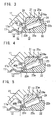
- Fig. 4 is a sectional view showing the modification in contrast with Fig. 3 in which the above described first embodiment is shown. It is to be noted that structure of this modification is the same as the structure in the above described first embodiment, except the structure as described below. Therefore, the components corresponding to those in the first embodiment will be denoted with the same reference numerals. In this modification, the structure of the inner ring 22 of the readymade tapered roller bearing 13 is different from that of the first embodiment.
- a labyrinth forming member 40A in a disc-like shape has a stepped shape in a sectional view which is stepped by a wall thickness of a rib part 24b of the cage 24.
- the labyrinth structure is formed between the rib part 24b of the cage 24 and a position having the stepped shape of the labyrinth forming member 40A, and the flow of the lubricating oil is properly restricted in the same manner as in the first embodiment.
- a second embodiment of the invention will be described.
- the second embodiment is shown in Fig. 5.
- Fig. 5 is a sectional view showing the second embodiment in contrast with Fig. 3 in which the above described first embodiment is shown. Accordingly, structure of the second embodiment too is the same as the structure in the above described first embodiment, except the structure as describedbelow. Therefore, the components corresponding to those in the first embodiment will be denoted with the same reference numerals..
- a labyrinth forming member 40B in a disc-like shape is integrally formed with a right end part of the spacer 17 in a cylindrical shape, as seen in Fig. 5 .
- the labyrinth structure is formed in the same manner as in the first embodiment, and the flow of the lubricating oil into the tapered roller bearing 13 is restricted to perform proper lubrication.
- the labyrinth forming member 40B is integrally formed with the end part of the spacer 17, it is possible to easily handle the labyrinth forming member 40B when it is fitted.
- the labyrinth forming member 40B is integrally formed with the spacer 17, it is possible to assemble the labyrinth forming member. 40B at the same time when the spacer is assembled. Therefore, the number of assembling steps will not be increased.
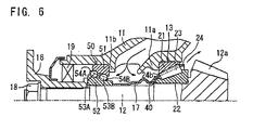
- Fig. 6 shows an embodiment in which a double row angular ball bearing 50 is employed as the angular contact type rolling bearing to be disposed forward.
- the double row angular ball bearing 50 as shown in Fig. 6 includes and outer ring 51, an inner ring 52, balls 53A, 53B in two rows, and two cages 54A, 54B.
- the balls 53A and 53B in two rows have the same diameter, and a pitch circle diameter of the ball 53A of the one row is made larger than a pitch circle diameter of the ball 53B of the other row. Further, contact angles of the balls 53A, 53B of the two rows are the same, and two action lines are inclined in the same direction. In some cases, the diameters and the contact angles of the balls 53A, 53B in the two rows may be made different.
- either of the labyrinth forming members 40, 40A, 40B is disposed so as to be opposed to a rib part at a small diameter side of a cage 54B of the ball 53B of the other row.
- a stirring resistance of the lubricating oil when the lubricating oil passes is smaller, as compared with the tapered roller bearing in which the rolling elements are tapered rollers in the above described embodiments. Therefore, there is less necessity of forming the labyrinth-structure than in case of the tapered roller bearing.
- the angular ball bearing 50 is employed as the forward bearing in which the flow of the lubricating oil is smaller than in the backward bearing, as in the structure as shown in Fig. 6 .
Landscapes
- Engineering & Computer Science (AREA)
- General Engineering & Computer Science (AREA)
- Mechanical Engineering (AREA)
- Rolling Contact Bearings (AREA)
- General Details Of Gearings (AREA)
- Sealing Of Bearings (AREA)
- Sealing Using Fluids, Sealing Without Contact, And Removal Of Oil (AREA)
Applications Claiming Priority (1)
| Application Number | Priority Date | Filing Date | Title |
|---|---|---|---|
| JP2007283033A JP2009108956A (ja) | 2007-10-31 | 2007-10-31 | ピニオン軸支持用軸受装置 |
Publications (2)
| Publication Number | Publication Date |
|---|---|
| EP2055972A2 true EP2055972A2 (de) | 2009-05-06 |
| EP2055972A3 EP2055972A3 (de) | 2010-04-07 |
Family
ID=40345638
Family Applications (1)
| Application Number | Title | Priority Date | Filing Date |
|---|---|---|---|
| EP08018984A Withdrawn EP2055972A3 (de) | 2007-10-31 | 2008-10-30 | Lageranordnung mit zwei geschmierten Wälzlagern zur Lagerung einer Ritzelwelle |
Country Status (3)
| Country | Link |
|---|---|
| US (1) | US20090110340A1 (de) |
| EP (1) | EP2055972A3 (de) |
| JP (1) | JP2009108956A (de) |
Cited By (1)
| Publication number | Priority date | Publication date | Assignee | Title |
|---|---|---|---|---|
| DE102009031068A1 (de) * | 2009-06-30 | 2011-01-05 | Aktiebolaget Skf | Lageranordnung und gelagertes Bauteil für ein Differentialgetriebe |
Families Citing this family (10)
| Publication number | Priority date | Publication date | Assignee | Title |
|---|---|---|---|---|
| JP5528964B2 (ja) | 2010-09-22 | 2014-06-25 | Ntn株式会社 | 転がり軸受 |
| JP5736778B2 (ja) * | 2011-01-06 | 2015-06-17 | 株式会社ジェイテクト | 円すいころ軸受及びこれを用いたピニオン軸支持装置 |
| JP5935420B2 (ja) * | 2012-03-16 | 2016-06-15 | 日本精工株式会社 | ディファレンシャルユニット |
| CN104395038B (zh) * | 2012-07-03 | 2016-12-14 | 阿特拉斯·科普柯工业技术公司 | 电动工具 |
| JP6442837B2 (ja) * | 2014-03-10 | 2018-12-26 | 株式会社ジェイテクト | 円錐ころ軸受 |
| DE102014216695B4 (de) * | 2014-08-22 | 2022-07-14 | Zf Friedrichshafen Ag | Distanzrohr für eine Kraftübertragungseinrichtung eines Drehflügelflugzeuges |
| DE102015219424A1 (de) * | 2015-10-07 | 2017-04-13 | Zf Friedrichshafen Ag | Lagereinheit umfassend zwei Wälzlager |
| JP6669096B2 (ja) * | 2017-02-06 | 2020-03-18 | トヨタ自動車株式会社 | 4輪駆動車両用デファレンシャル装置 |
| JP6909089B2 (ja) * | 2017-07-28 | 2021-07-28 | Ntn株式会社 | 複列自動調心ころ軸受 |
| CN115076225B (zh) * | 2022-06-07 | 2023-08-04 | 山东华工轴承有限公司 | 基于风力发电主轴用双列异形自动调心滚子轴承 |
Citations (2)
| Publication number | Priority date | Publication date | Assignee | Title |
|---|---|---|---|---|
| JP2005069421A (ja) | 2003-08-27 | 2005-03-17 | Koyo Seiko Co Ltd | 円すいころ軸受 |
| JP2005273796A (ja) | 2004-03-25 | 2005-10-06 | Koyo Seiko Co Ltd | ピニオン軸支持用軸受装置 |
Family Cites Families (5)
| Publication number | Priority date | Publication date | Assignee | Title |
|---|---|---|---|---|
| US3318173A (en) * | 1965-03-19 | 1967-05-09 | American Motors Corp | Differential gear assembly |
| JPH08210472A (ja) * | 1995-02-02 | 1996-08-20 | Toyota Motor Corp | 終減速装置の潤滑機構 |
| JPH1151159A (ja) * | 1997-07-31 | 1999-02-23 | Nippon Seiko Kk | 終減速装置用ピニオン軸の軸受装置 |
| JP4449815B2 (ja) * | 2005-04-28 | 2010-04-14 | 株式会社ジェイテクト | 液体潤滑式円錐ころ軸受装置および車両用ピニオン軸支持装置 |
| JP2007100780A (ja) * | 2005-10-03 | 2007-04-19 | Gkn ドライブライン トルクテクノロジー株式会社 | 軸支持構造 |
-
2007
- 2007-10-31 JP JP2007283033A patent/JP2009108956A/ja active Pending
-
2008
- 2008-10-30 EP EP08018984A patent/EP2055972A3/de not_active Withdrawn
- 2008-10-30 US US12/289,585 patent/US20090110340A1/en not_active Abandoned
Patent Citations (2)
| Publication number | Priority date | Publication date | Assignee | Title |
|---|---|---|---|---|
| JP2005069421A (ja) | 2003-08-27 | 2005-03-17 | Koyo Seiko Co Ltd | 円すいころ軸受 |
| JP2005273796A (ja) | 2004-03-25 | 2005-10-06 | Koyo Seiko Co Ltd | ピニオン軸支持用軸受装置 |
Cited By (1)
| Publication number | Priority date | Publication date | Assignee | Title |
|---|---|---|---|---|
| DE102009031068A1 (de) * | 2009-06-30 | 2011-01-05 | Aktiebolaget Skf | Lageranordnung und gelagertes Bauteil für ein Differentialgetriebe |
Also Published As
| Publication number | Publication date |
|---|---|
| EP2055972A3 (de) | 2010-04-07 |
| US20090110340A1 (en) | 2009-04-30 |
| JP2009108956A (ja) | 2009-05-21 |
Similar Documents
| Publication | Publication Date | Title |
|---|---|---|
| EP2055972A2 (de) | Lageranordnung mit zwei geschmierten Wälzlagern zur Lagerung einer Ritzelwelle | |
| EP2749782B1 (de) | Flüssigkeitsgeschmiertes Lager und Stützvorrichtung einer Ritzelwelle eines Fauhrzeuges. | |
| JP2005273796A (ja) | ピニオン軸支持用軸受装置 | |
| JP2016180417A (ja) | 円すいころ軸受 | |
| EP1876366A2 (de) | Schmierstruktur für ein Kugellager | |
| WO2012033043A1 (ja) | 減速装置 | |
| US9382945B2 (en) | Mechanical device comprising a bearing and a lubrication system, implementing machine and method | |
| JP2001010304A (ja) | 車輪支持用ハブユニット及びその組立方法 | |
| JP7261599B2 (ja) | 車輪用軸受装置 | |
| CN112585365B (zh) | 车轮用轴承装置 | |
| JP6171444B2 (ja) | 転がり軸受装置及び車両用ピニオン軸支持装置 | |
| WO2019189421A1 (ja) | 車輪用軸受装置 | |
| JP6248674B2 (ja) | スラストころ軸受 | |
| CN104791380A (zh) | 调心滚子轴承 | |
| JP2014159872A (ja) | 円すいころ軸受 | |
| JP2013024377A (ja) | 円すいころ軸受用樹脂製保持器及び円すいころ軸受 | |
| JP2021162074A (ja) | 円すいころ軸受及び保持器 | |
| JP2009293656A (ja) | スラストころ軸受 | |
| JP4411831B2 (ja) | 複列玉軸受用組品および該組品を用いる装置の組立方法 | |
| JP2003120684A (ja) | スラストころ軸受 | |
| JP5067338B2 (ja) | ラジアル・スラスト組み合わせ軸受 | |
| JP4244955B2 (ja) | 自動車用ハブユニットの組立方法 | |
| JP2009191939A (ja) | 円すいころ軸受 | |
| JP2012177400A (ja) | 減速装置 | |
| JP6236754B2 (ja) | タンデム型複列アンギュラ玉軸受、デファレンシャル装置、及び、自動車 |
Legal Events
| Date | Code | Title | Description |
|---|---|---|---|
| PUAI | Public reference made under article 153(3) epc to a published international application that has entered the european phase |
Free format text: ORIGINAL CODE: 0009012 |
|
| AK | Designated contracting states |
Kind code of ref document: A2 Designated state(s): AT BE BG CH CY CZ DE DK EE ES FI FR GB GR HR HU IE IS IT LI LT LU LV MC MT NL NO PL PT RO SE SI SK TR |
|
| AX | Request for extension of the european patent |
Extension state: AL BA MK RS |
|
| PUAL | Search report despatched |
Free format text: ORIGINAL CODE: 0009013 |
|
| AK | Designated contracting states |
Kind code of ref document: A3 Designated state(s): AT BE BG CH CY CZ DE DK EE ES FI FR GB GR HR HU IE IS IT LI LT LU LV MC MT NL NO PL PT RO SE SI SK TR |
|
| AX | Request for extension of the european patent |
Extension state: AL BA MK RS |
|
| AKY | No designation fees paid | ||
| STAA | Information on the status of an ep patent application or granted ep patent |
Free format text: STATUS: THE APPLICATION IS DEEMED TO BE WITHDRAWN |
|
| 18D | Application deemed to be withdrawn |
Effective date: 20101008 |
|
| REG | Reference to a national code |
Ref country code: DE Ref legal event code: R108 Effective date: 20110412 |