EP2056040A1 - Entretoise pour les tuyaux d'une sonde géothermique - Google Patents
Entretoise pour les tuyaux d'une sonde géothermique Download PDFInfo
- Publication number
- EP2056040A1 EP2056040A1 EP08168100A EP08168100A EP2056040A1 EP 2056040 A1 EP2056040 A1 EP 2056040A1 EP 08168100 A EP08168100 A EP 08168100A EP 08168100 A EP08168100 A EP 08168100A EP 2056040 A1 EP2056040 A1 EP 2056040A1
- Authority
- EP
- European Patent Office
- Prior art keywords
- probe
- receiving
- holder
- tubes
- spacer
- Prior art date
- Legal status (The legal status is an assumption and is not a legal conclusion. Google has not performed a legal analysis and makes no representation as to the accuracy of the status listed.)
- Withdrawn
Links
- 239000000523 sample Substances 0.000 title claims abstract description 132
- 125000006850 spacer group Chemical group 0.000 title claims abstract description 65
- 238000002347 injection Methods 0.000 claims description 26
- 239000007924 injection Substances 0.000 claims description 26
- 238000003780 insertion Methods 0.000 claims description 8
- 230000037431 insertion Effects 0.000 claims description 8
- 239000013529 heat transfer fluid Substances 0.000 claims description 7
- 230000004323 axial length Effects 0.000 claims description 3
- 239000004033 plastic Substances 0.000 description 7
- 229920003023 plastic Polymers 0.000 description 7
- XLYOFNOQVPJJNP-UHFFFAOYSA-N water Substances O XLYOFNOQVPJJNP-UHFFFAOYSA-N 0.000 description 7
- 239000000463 material Substances 0.000 description 5
- 238000010438 heat treatment Methods 0.000 description 4
- -1 polyethylene Polymers 0.000 description 4
- 239000004698 Polyethylene Substances 0.000 description 3
- 238000013461 design Methods 0.000 description 3
- 238000004519 manufacturing process Methods 0.000 description 3
- 229920000573 polyethylene Polymers 0.000 description 3
- 238000012546 transfer Methods 0.000 description 3
- 230000001419 dependent effect Effects 0.000 description 2
- 238000001746 injection moulding Methods 0.000 description 2
- 239000007788 liquid Substances 0.000 description 2
- 238000000034 method Methods 0.000 description 2
- 239000002689 soil Substances 0.000 description 2
- 239000000243 solution Substances 0.000 description 2
- BLDFSDCBQJUWFG-UHFFFAOYSA-N 2-(methylamino)-1,2-diphenylethanol Chemical compound C=1C=CC=CC=1C(NC)C(O)C1=CC=CC=C1 BLDFSDCBQJUWFG-UHFFFAOYSA-N 0.000 description 1
- 238000005299 abrasion Methods 0.000 description 1
- 230000004913 activation Effects 0.000 description 1
- 239000000809 air pollutant Substances 0.000 description 1
- 231100001243 air pollutant Toxicity 0.000 description 1
- 229910000278 bentonite Inorganic materials 0.000 description 1
- 239000000440 bentonite Substances 0.000 description 1
- SVPXDRXYRYOSEX-UHFFFAOYSA-N bentoquatam Chemical compound O.O=[Si]=O.O=[Al]O[Al]=O SVPXDRXYRYOSEX-UHFFFAOYSA-N 0.000 description 1
- 239000004568 cement Substances 0.000 description 1
- 230000008094 contradictory effect Effects 0.000 description 1
- 238000011161 development Methods 0.000 description 1
- 230000018109 developmental process Effects 0.000 description 1
- 238000005553 drilling Methods 0.000 description 1
- 238000005516 engineering process Methods 0.000 description 1
- 239000000284 extract Substances 0.000 description 1
- 239000002803 fossil fuel Substances 0.000 description 1
- 229920001179 medium density polyethylene Polymers 0.000 description 1
- 239000004701 medium-density polyethylene Substances 0.000 description 1
- 230000003446 memory effect Effects 0.000 description 1
- 239000000203 mixture Substances 0.000 description 1
- 229920000642 polymer Polymers 0.000 description 1
- 239000003507 refrigerant Substances 0.000 description 1
- 230000000284 resting effect Effects 0.000 description 1
- 239000011435 rock Substances 0.000 description 1
- 238000007789 sealing Methods 0.000 description 1
- 230000008961 swelling Effects 0.000 description 1
- 238000012549 training Methods 0.000 description 1
- 230000001960 triggered effect Effects 0.000 description 1
Images


Classifications
-
- F—MECHANICAL ENGINEERING; LIGHTING; HEATING; WEAPONS; BLASTING
- F28—HEAT EXCHANGE IN GENERAL
- F28D—HEAT-EXCHANGE APPARATUS, NOT PROVIDED FOR IN ANOTHER SUBCLASS, IN WHICH THE HEAT-EXCHANGE MEDIA DO NOT COME INTO DIRECT CONTACT
- F28D20/00—Heat storage plants or apparatus in general; Regenerative heat-exchange apparatus not covered by groups F28D17/00 or F28D19/00
- F28D20/0052—Heat storage plants or apparatus in general; Regenerative heat-exchange apparatus not covered by groups F28D17/00 or F28D19/00 using the ground body or aquifers as heat storage medium
-
- E—FIXED CONSTRUCTIONS
- E21—EARTH OR ROCK DRILLING; MINING
- E21B—EARTH OR ROCK DRILLING; OBTAINING OIL, GAS, WATER, SOLUBLE OR MELTABLE MATERIALS OR A SLURRY OF MINERALS FROM WELLS
- E21B17/00—Drilling rods or pipes; Flexible drill strings; Kellies; Drill collars; Sucker rods; Cables; Casings; Tubings
- E21B17/10—Wear protectors; Centralising devices, e.g. stabilisers
- E21B17/1035—Wear protectors; Centralising devices, e.g. stabilisers for plural rods, pipes or lines, e.g. for control lines
-
- F—MECHANICAL ENGINEERING; LIGHTING; HEATING; WEAPONS; BLASTING
- F24—HEATING; RANGES; VENTILATING
- F24T—GEOTHERMAL COLLECTORS; GEOTHERMAL SYSTEMS
- F24T10/00—Geothermal collectors
- F24T10/10—Geothermal collectors with circulation of working fluids through underground channels, the working fluids not coming into direct contact with the ground
-
- Y—GENERAL TAGGING OF NEW TECHNOLOGICAL DEVELOPMENTS; GENERAL TAGGING OF CROSS-SECTIONAL TECHNOLOGIES SPANNING OVER SEVERAL SECTIONS OF THE IPC; TECHNICAL SUBJECTS COVERED BY FORMER USPC CROSS-REFERENCE ART COLLECTIONS [XRACs] AND DIGESTS
- Y02—TECHNOLOGIES OR APPLICATIONS FOR MITIGATION OR ADAPTATION AGAINST CLIMATE CHANGE
- Y02E—REDUCTION OF GREENHOUSE GAS [GHG] EMISSIONS, RELATED TO ENERGY GENERATION, TRANSMISSION OR DISTRIBUTION
- Y02E10/00—Energy generation through renewable energy sources
- Y02E10/10—Geothermal energy
-
- Y—GENERAL TAGGING OF NEW TECHNOLOGICAL DEVELOPMENTS; GENERAL TAGGING OF CROSS-SECTIONAL TECHNOLOGIES SPANNING OVER SEVERAL SECTIONS OF THE IPC; TECHNICAL SUBJECTS COVERED BY FORMER USPC CROSS-REFERENCE ART COLLECTIONS [XRACs] AND DIGESTS
- Y02—TECHNOLOGIES OR APPLICATIONS FOR MITIGATION OR ADAPTATION AGAINST CLIMATE CHANGE
- Y02E—REDUCTION OF GREENHOUSE GAS [GHG] EMISSIONS, RELATED TO ENERGY GENERATION, TRANSMISSION OR DISTRIBUTION
- Y02E60/00—Enabling technologies; Technologies with a potential or indirect contribution to GHG emissions mitigation
- Y02E60/14—Thermal energy storage
-
- Y—GENERAL TAGGING OF NEW TECHNOLOGICAL DEVELOPMENTS; GENERAL TAGGING OF CROSS-SECTIONAL TECHNOLOGIES SPANNING OVER SEVERAL SECTIONS OF THE IPC; TECHNICAL SUBJECTS COVERED BY FORMER USPC CROSS-REFERENCE ART COLLECTIONS [XRACs] AND DIGESTS
- Y02—TECHNOLOGIES OR APPLICATIONS FOR MITIGATION OR ADAPTATION AGAINST CLIMATE CHANGE
- Y02E—REDUCTION OF GREENHOUSE GAS [GHG] EMISSIONS, RELATED TO ENERGY GENERATION, TRANSMISSION OR DISTRIBUTION
- Y02E70/00—Other energy conversion or management systems reducing GHG emissions
- Y02E70/30—Systems combining energy storage with energy generation of non-fossil origin
Definitions
- the invention relates to a spacer for the probe tubes of a geothermal probe for use in deep wells according to the preamble of patent claim 1.
- Geothermal energy or geothermal energy is the energy stored in the form of heat below the earth's surface.
- the soil has an approximately constant temperature throughout the year, which increases with increasing depth. This temperature is determined by the heat flow from the Earth's interior.
- the heat is usually obtained by means of geothermal probes, which are installed in a vertical, densely back-filled bore of usually 50 to 350 m depth.
- the compact backfilling of the deep hole ensures a trouble-free heat flow between the ground and the geothermal probe and prevents unwanted vertical seepage flows along the probe.
- a heat transfer medium usually a heat transfer fluid through which heat is removed from the ground by means of a heat pump. It is also possible to derive excess heat in the ground by reversing the process, for example, to cool a building in the summer.
- the geothermal probe has at least two, usually four probe tubes, which are connected in pairs to form a U. In each case one of the probe tubes serves as a flow, while the other probe tube forms the return for the circulating in the geothermal probe heat transfer fluid.
- the connection of a probe tube pair is arranged inside a probe head, which is advanced to the bottom of the deep hole. Between the probe tubes is an injection tube arranged, which is advanced together with the geothermal probe into the bore and serves to backfill the bore.
- the probe tubes and the injection tube are usually made of plastic, for example of polyethylene, and usually have wall thicknesses of about 2.5 mm to about 5 mm.
- the pipe diameter is usually about 30 mm to about 50 mm.
- Geothermal probes capture the heat in deep wells, which can be up to 350 m deep. At these depths, it is immediately apparent that the probe tubes and the injection tube must be fixed in terms of their relative position so that the geothermal probe can be inserted and advanced without difficulty in the bore. It must also be prevented that the flow and return probe tubes come into contact with each other, as this can lead to heat loss. Adjacent probe tubes can also affect the backfill of the deep hole. For the relative determination of the position of the probe tubes therefore clip-like spacers are already known, which are connected in pairs by a spring clip. The clip-like spacers are connected at certain axial distances from each other with a flow and a return probe tube.
- Detachable latches on the clip-type spacers ensure that the spring clips of the spacers are held in a tensioned condition in which the probe tubes are only a small distance apart so as to be easier to insert and advance into the bore. After the geothermal probe has been advanced to the intended depth, the latches are released, and the probe tubes held in the clip-like spacers are urged against the bore wall by the spring clips.
- the probe tubes resting against the bore wall can prove problematic, especially in the case of water-bearing layers. Water from a higher layer can get along the probe tubes in an underlying layer, but this should be prevented.
- a geothermal probe within a deep hole drilling in operation with circulating heat transfer fluid is a dynamic system. Despite the backfilling of the bore it comes to movements the probe tubes, which can even be damaged by the constant friction on the bore wall.
- a heat exchanger to be used in a borehole comprises at least one heat exchanger element of practically parallel tubes with adjustable distances between them. This document teaches that the distance of the tubes should be increased so far in the radial direction of the well that the pipe walls come into firm contact with the well.
- a disadvantage of this device is that friction between the borehole and the heat exchanger element can occur during operation of the heat exchanger, which can lead to abrasion of the pipe wall, and that the sealing of the borehole against ingress of water in the area between the pipe wall and the borehole can be insufficient ,
- the object of the present invention is to provide a spacer for the probe tubes of a geothermal probe, which holds the probe tubes for insertion into the bore at a small distance from each other and has the least possible friction on the bore wall, and the tubes after their introduction centrally in the bore supports, but prevents friction between the bore wall and pipe.
- the proposed by the invention spacer is designed for use in conjunction with a geothermal probe having at least two probe tubes, one of which forms a flow and the other probe tube forms a return for a heat transfer fluid and which are connected to a probe head.
- the spacer has at least two receiving shells for the probe tubes, which are interconnected by a holder.
- the holder is in a first end position in which the receiving shells have a first distance from each other, fixed and can be brought into a second state in which the receiving shells for the probe tubes have a greater distance from each other than in the first end position.
- On the receiving shells for the probe tubes spacer projections are arranged, which protrude respectively from one of the holder facing away from the outer side of the receiving trays.
- the spacer By the spacer is equipped according to the invention on the receiving shells for the probe tubes with distance projections, the probe tubes held in the receiving shells come in the assembled state no longer in contact with the borehole wall.
- the spacer according to the invention also has a holder that can be brought into two states. In a first end position of the holder, the receiving shells for the probe tubes at a small distance from each other. In this end position, which can be fixed, the geothermal probe can be easily inserted into the bore and advanced to the bottom of the hole. When the end position of the geothermal probe is reached, the holder is expanded until the distance projections provided on the receiving shells rest against the borehole wall.
- the receiving cups are arranged in pairs approximately diagonally opposite to the holder.
- the receiving trays have the greatest possible distance from each other.
- this arrangement also relatively simple conditions to expand the spacer when needed, for example, to unfold.
- the receiving shells have an approximately C-shaped contour in plan view.
- one end of the C-leg is connected to the holder, while the opposite end of the C-leg has the distance projection. Due to the design of the receiving shells as a lying "C" a clipped probe tube is already largely shielded by the C-leg of the receiving tray to the periphery.
- the spacer projection is arranged on the outside of the C-leg, that it protrudes approximately in the axial extension of the holder of the receiving tray. Due to the axial arrangement of the spacer projections act in the expanded state of the holder only axial forces on the holder. Additional lateral forces that would require a more stable design of the holder can be largely avoided.
- the C-shaped receiving shells have insertion openings for the probe tubes, which are arranged approximately perpendicular to the extension of the holder.
- pairs of opposing receiving cups have mutually oppositely arranged insertion openings for the probe tubes.
- spacer projections which have an axial length of about 10% to about 30% of the inside diameter of a receiving shell prove to be expedient.
- the spacer projections may be separate parts which are mounted on the outside of the spacers.
- the distance projections are formed integrally with the receiving tray.
- receiving shells can be produced with integrated distance projections, for example in mass-proven plastic injection molding.
- a geothermal probe has at least one flow and a return for the heat transfer fluid.
- the flow and the return are connected to a probe head and form a U-tube.
- the two legs of the U are formed by the two probe tubes, which are held in the spacer.
- the spacer is equipped with four receiving tubes for probe tubes.
- the receiving shells are each connected in pairs opposite to the holder and arranged approximately at equal angular intervals from each other.
- the holder has a cruciform shape.
- the individual arms of the brackets can be designed to be pushed together and equipped with springs, which bias the arms in the collapsed state.
- a releasable lock ensures that the arms remain in the collapsed state until the lock is released.
- the holder may be formed by a plastic which is fixable in a compressed state of the arms and is expandable if necessary.
- a very expedient embodiment of the spacer provides that the holder for the receiving trays has a recess for receiving an injection tube has, which is arranged approximately centrally between the receiving trays.
- This variant is suitable for spacers for two probe tubes as well as for those for geothermal probes with four probe tubes.
- the injection tube is inserted with the heating probe into the deep hole and advanced. It is used for later backfilling of the borehole.
- the recess in the holder serves to define and guide the injection tube.
- the injection tube can also be used to release a latch which holds the holder in the first, compressed end position. For example, this can be done by an axial relative movement between the spacers and guided through the recesses in the brackets injection pipe.
- the release of the lock can be done, for example, by an increase in the diameter of the guided in the recesses injection pipe.
- a further embodiment of the spacer may provide that the holder has a receiver device for mechanical, thermal or electromagnetic energy.
- the receiver device makes it possible to convert the holder from its first end position, in which the receiving cups are at a first distance from each other, into the second state, in which the receiving tubes for the probe tubes have a second distance from one another which is greater than the distance in the latter first end position.
- the receiver device is expediently connected to a releasable locking device.
- the lock can be triggered, for example, by radio signals, by a guided through the probe tubes refrigerant or the like.
- the receiving shells for the probe tubes are directly connected to an injection tube, which serves to backfill the borehole.
- the injection tube itself forms the holder for the receiving trays.
- the injection tube consists for example of a plastic, which can be converted from a first state in which the injection tube has a smaller diameter in a second stable state, in which the Diameter of the injection tube is increased. This can be done for example by overpressure or by swelling of the material.
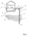
- the schematic sectional view in Fig. 1 shows the principle of Erdettasondentechnologie the example of heating a building B.
- a geothermal probe 5 which is inserted into a deep hole 1 of about 50 - 350 m, connected via a feed line 6 to a heat pump 7.
- the heat pump 7 supplies a heating system 8 of the building B with the required amount of hot water.
- the geothermal probe 5 inserted into the deep hole 1 is a heat exchanger in which a liquid circulates.
- the geothermal probe 5 four probe tubes made of polyethylene, which are combined in pairs to form a U-tube and are connected to the supply line 6 to the heat pump 7.
- the probe tubes have, for example, diameters of 32 mm or 40 mm.
- the geothermal probe 5 is advanced to the bottom 3 of the hole.
- the between the geothermal probe 5 and the bore wall 2 remaining cavity is backfilled with a backfill 4, which consists for example of a mixture of bentonite and cement, compact, to ensure good thermal contact between the probe tubes of geothermal probe 5 and the bore wall 2.
- a backfill 4 which consists for example of a mixture of bentonite and cement, compact, to ensure good thermal contact between the probe tubes of geothermal probe 5 and the bore wall 2.
- backfill 4 other materials come into question, which ensure a sufficiently good heat transfer.
- water is used as filling material.
- the circulating in the probe tubes liquid usually water with a share of 15 - 20% Antigel, extracts the ground G ground heat and supplies the heat pump 7 with this geothermal energy. With the heat pump 7, the temperature is then raised to the level required for heating purposes.
- Fig. 1 is also indicated that the background G usually composed of shallower softer soil S and hard Fel füren R.
- Fig. 2 shows the geothermal probe 5 on a larger scale.
- the geothermal probe 5 has a probe head 51 and four probe tubes 51, 52, 53, 54, which are combined in pairs and are connected in the probe head 51 to a U-shaped tube, with always two of the probe tubes 52, 54 a flow and the other two probe tubes 53, 55 form a return for a circulating in the geothermal probe 5 heat transfer fluid.
- the connecting pieces of the probe tubes 52, 53 and 54, 55 are designated by the reference numerals 56 and 57, respectively, and disposed within the probe head 51.
- Such geothermal probes 5 are known, for example, under the name duplex ground probe.
- an injection tube 9 is provided, which is arranged between the probe tubes 51-54 and is advanced together with the geothermal probe 5 into the deep hole.
- the diameter of the probe tubes 52-55 is for example 40 mm.
- the diameter of the injection tube 9 is for example 32 mm.
- the injection tube has a wall thickness of about 2.9 mm.
- the wall thickness of the probe tubes 52-55 is for example 3.7 mm.
- FIG. 3 and 4 show a mounted on a geothermal probe spacers 10 in two states. It shows Fig. 3 the spacer 10 in the state for introducing and advancing the Erdméremsonde in a deep hole. Fig. 4 shows an expanded spacer 10 at a fully extended to the bottom of the wellbore 1 geothermal probe.
- the spacer 10 has four C-shaped clip-like receiving cups 11,12,13,14 for the probe tubes 52, 53, 54, 55 of the geothermal probe.
- the receiving shells 11-14 are connected to a holder 16 which has two mutually perpendicular arms 17, 18. Each receiving dish 11-14 is provided with an insertion opening 15 for the probe tubes 52-55, which points in each case to the half-shell-like C-leg of the adjacent receiving dish.
- the holder 16 has a recess 19 which serves to guide the inserted injection tube 9.
- the axial length of the spacer projections 20 is in each case about 10% to about 30% of the inner diameter of a receiving tray 11 -14.
- the spacer projections 20 may be formed as separate components and be mounted on the outer surfaces of the receiving cups 11-14.
- the spacer projections 20 are integrally formed with the C-shaped receiving cups 11-14.
- integrally molded spacer projections can be very simple example, produce in a plastic injection molding process.
- a first end position in which the receiving cups 11 - 14 have a first, small distance from each other.
- the arms 17,18 of the holder 16 may be telescopically collapsible against the restoring force of a spring, for example.
- a non-illustrated releasable locking device is provided to fix the holder 16 in the first end position.
- the holder may for example also be formed by a polymer body which has been brought by pressure into its first end position and only expanded again by mechanical, thermal or electromagnetic energy supply by utilizing a memory effect.
- Fig. 4 shows the spacer 10 in its expanded state.
- the spacer 10 is brought into this state when the geothermal probe has been advanced to the bottom of the deep hole 1.
- 16 receiver devices not shown in detail can be provided on the holder, which implement a supply of mechanical, thermal or electromagnetic energy in a solution of a lock and / or in an activation of the expansion.
- the arms 17,18 of the holder 16 expand until the spacer projections 20, which protrude from the outer surfaces of the receiving shells 11-14 for the probe tubes 52-55, abut against the borehole wall 2.
- the spacer projections 20 prevent the probe tubes 52-55 from coming into direct contact with the borehole wall 2. As a result, damage can be avoided and heat losses prevented.
- the probe tubes 52-55 are held in a well-defined position in the wellbore 1. This also facilitates the backfilling of the deep hole 1 via the injection tube 9. The distances of the probe tubes 52-55 from each other prevent heat transfer from the returns to the feeders.
- the spacers can be easily mounted on the probe tubes of the geothermal probe;
- the probe tubes need only be clipped into the receiving trays. They do not hinder the insertion and advancement of the geothermal probe in the deep hole. After reaching the bottom of the hole, the holder by energy, for example, by axial pulling on the injection tube, easily expandable.
- the spacer has been explained using the example of a geothermal probe having four probe tubes. It is understood, however, that the spacer can also be designed for the determination of geothermal probes with only two probe tubes.
- the holder has only one arm, at the ends of the receiving tubes for the probe tubes are mounted.
Landscapes
- Engineering & Computer Science (AREA)
- Mechanical Engineering (AREA)
- Life Sciences & Earth Sciences (AREA)
- General Engineering & Computer Science (AREA)
- Physics & Mathematics (AREA)
- Chemical & Material Sciences (AREA)
- Sustainable Development (AREA)
- Sustainable Energy (AREA)
- Thermal Sciences (AREA)
- Combustion & Propulsion (AREA)
- Geology (AREA)
- Mining & Mineral Resources (AREA)
- Environmental & Geological Engineering (AREA)
- Fluid Mechanics (AREA)
- General Life Sciences & Earth Sciences (AREA)
- Geochemistry & Mineralogy (AREA)
- Geophysics And Detection Of Objects (AREA)
Applications Claiming Priority (1)
| Application Number | Priority Date | Filing Date | Title |
|---|---|---|---|
| CH16892007 | 2007-10-31 |
Publications (1)
| Publication Number | Publication Date |
|---|---|
| EP2056040A1 true EP2056040A1 (fr) | 2009-05-06 |
Family
ID=39126141
Family Applications (1)
| Application Number | Title | Priority Date | Filing Date |
|---|---|---|---|
| EP08168100A Withdrawn EP2056040A1 (fr) | 2007-10-31 | 2008-10-31 | Entretoise pour les tuyaux d'une sonde géothermique |
Country Status (1)
| Country | Link |
|---|---|
| EP (1) | EP2056040A1 (fr) |
Cited By (9)
| Publication number | Priority date | Publication date | Assignee | Title |
|---|---|---|---|---|
| DE102010014870A1 (de) * | 2010-03-02 | 2011-09-08 | Mat_C Gmbh | Abstandshalter für Erdwärmesonden, Erdwärmesondenbündel, Sondenfuss, Verwendung und Verfahren |
| WO2011113146A1 (fr) * | 2010-03-16 | 2011-09-22 | Supranergie Inc. | Elément d'espacement pour tuyau |
| DE102010019411A1 (de) * | 2010-05-04 | 2011-11-10 | Sts Spezial-Tiefbau-Systeme Gmbh | Injektions-Kammersonde |
| WO2013091854A1 (fr) * | 2011-12-21 | 2013-06-27 | Rehau Ag + Co | Dispositif à sonde géothermique |
| JP2014020645A (ja) * | 2012-07-17 | 2014-02-03 | Ohbayashi Corp | 保持部材 |
| JP2014070697A (ja) * | 2012-09-28 | 2014-04-21 | Sekisui Chem Co Ltd | チューブ保持スペーサ |
| EP2738480A3 (fr) * | 2012-11-29 | 2014-06-11 | Jansen AG | Corps de sonde |
| EP2738481A3 (fr) * | 2012-11-29 | 2014-06-11 | Jansen AG | Corps de sonde |
| CN112923592A (zh) * | 2021-03-30 | 2021-06-08 | 西安中亚科技发展有限公司 | 一种中深层无干扰地热能高效同轴换热装置 |
Citations (6)
| Publication number | Priority date | Publication date | Assignee | Title |
|---|---|---|---|---|
| EP0207911A1 (fr) | 1985-07-02 | 1987-01-07 | Palne Mogensen | Procédé et moyens pour appliquer un échangeur de chaleur dans un puits de forage pour récupérer et stocker de la chaleur |
| EP0207910A1 (fr) | 1985-07-01 | 1987-01-07 | Ab Volvo | Transmission pour véhicule à moteur |
| DE29615594U1 (de) * | 1996-09-02 | 1997-01-02 | Scherf, Bernhard, Dipl.-Ing., 03229 Altdöbern | Abstandshalter für Rohrstränge von Erdsonden |
| US6000459A (en) * | 1999-05-14 | 1999-12-14 | Jeppesen; Kris | U-bend pipe spacer |
| DE202007005796U1 (de) | 2007-04-21 | 2007-08-02 | Müller, Hans-Werner | Abstandhalter zur achsparallelen Fixierung mehrerer Rohrstränge |
| DE202007005268U1 (de) * | 2007-04-10 | 2007-08-02 | Pumpenboese Gmbh & Co. Kg | Erdwärmesonde und Zentrierelement für Erdwärmesonden |
-
2008
- 2008-10-31 EP EP08168100A patent/EP2056040A1/fr not_active Withdrawn
Patent Citations (7)
| Publication number | Priority date | Publication date | Assignee | Title |
|---|---|---|---|---|
| EP0207910A1 (fr) | 1985-07-01 | 1987-01-07 | Ab Volvo | Transmission pour véhicule à moteur |
| EP0207911A1 (fr) | 1985-07-02 | 1987-01-07 | Palne Mogensen | Procédé et moyens pour appliquer un échangeur de chaleur dans un puits de forage pour récupérer et stocker de la chaleur |
| US4867229A (en) * | 1985-07-02 | 1989-09-19 | Palne Mogensen | Method and means for applying a heat exchanger in a drill hole for the purpose of heat recovery or storage |
| DE29615594U1 (de) * | 1996-09-02 | 1997-01-02 | Scherf, Bernhard, Dipl.-Ing., 03229 Altdöbern | Abstandshalter für Rohrstränge von Erdsonden |
| US6000459A (en) * | 1999-05-14 | 1999-12-14 | Jeppesen; Kris | U-bend pipe spacer |
| DE202007005268U1 (de) * | 2007-04-10 | 2007-08-02 | Pumpenboese Gmbh & Co. Kg | Erdwärmesonde und Zentrierelement für Erdwärmesonden |
| DE202007005796U1 (de) | 2007-04-21 | 2007-08-02 | Müller, Hans-Werner | Abstandhalter zur achsparallelen Fixierung mehrerer Rohrstränge |
Cited By (12)
| Publication number | Priority date | Publication date | Assignee | Title |
|---|---|---|---|---|
| DE102010014870A1 (de) * | 2010-03-02 | 2011-09-08 | Mat_C Gmbh | Abstandshalter für Erdwärmesonden, Erdwärmesondenbündel, Sondenfuss, Verwendung und Verfahren |
| WO2011113146A1 (fr) * | 2010-03-16 | 2011-09-22 | Supranergie Inc. | Elément d'espacement pour tuyau |
| US8398034B2 (en) | 2010-03-16 | 2013-03-19 | Supranergie Inc. | Pipe spacer |
| DE102010019411A1 (de) * | 2010-05-04 | 2011-11-10 | Sts Spezial-Tiefbau-Systeme Gmbh | Injektions-Kammersonde |
| EP2385328A3 (fr) * | 2010-05-04 | 2013-04-24 | STS Spezial-Tiefbau-Systeme GmbH | Sonde géothermique à injection |
| DE102010019411B4 (de) * | 2010-05-04 | 2015-01-22 | Sts Spezial-Tiefbau-Systeme Gmbh | Injektions-Kammersonde |
| WO2013091854A1 (fr) * | 2011-12-21 | 2013-06-27 | Rehau Ag + Co | Dispositif à sonde géothermique |
| JP2014020645A (ja) * | 2012-07-17 | 2014-02-03 | Ohbayashi Corp | 保持部材 |
| JP2014070697A (ja) * | 2012-09-28 | 2014-04-21 | Sekisui Chem Co Ltd | チューブ保持スペーサ |
| EP2738480A3 (fr) * | 2012-11-29 | 2014-06-11 | Jansen AG | Corps de sonde |
| EP2738481A3 (fr) * | 2012-11-29 | 2014-06-11 | Jansen AG | Corps de sonde |
| CN112923592A (zh) * | 2021-03-30 | 2021-06-08 | 西安中亚科技发展有限公司 | 一种中深层无干扰地热能高效同轴换热装置 |
Similar Documents
| Publication | Publication Date | Title |
|---|---|---|
| EP0017783B1 (fr) | Dispositif pour utiliser la chaleur du sol et procédé pour la production de ce dispositif | |
| EP2035656B1 (fr) | Procédé pour sceller les parois d'un sondage | |
| DE202007005796U1 (de) | Abstandhalter zur achsparallelen Fixierung mehrerer Rohrstränge | |
| DE3701187C2 (de) | Anordnung zur Energieübertragung auf eine für die Prospektion des Untergrundes geeignete Vorrichtung innerhalb eines Bohrlochs | |
| EP1006322A2 (fr) | Procédé de mise en place d'un échangeur de chaleur dans le sol et échangeur de chaleur souterrain | |
| CH671093A5 (en) | Borehole test probe inserting appts. - uses drill rod string to apply pressure to spacer tube attached to bent probe | |
| WO2009129778A2 (fr) | Pied de sonde à structure modulaire et ses composants | |
| DE102013006416B4 (de) | Erdwärmesonde | |
| WO2012056011A1 (fr) | Procédé d'introduction sous terre d'une canalisation | |
| EP2357317A2 (fr) | Procédé de rénovation d'un forage dans la terre | |
| DE20021105U1 (de) | Sondenfuß | |
| DE102007036749A1 (de) | Solarkollektor zum Erwärmen einer Flüssigkeit | |
| WO2011015341A1 (fr) | Dispositif de pose d'une sonde géothermique | |
| CH669427A5 (fr) | ||
| WO2011015342A1 (fr) | Dispositif de pose de sonde géothermique | |
| DE102010008710B4 (de) | Verfahren zum Verlegen von Geothermiesonden und Geothermiesondengewerk | |
| DE20306216U1 (de) | Endsondenumlenkfuß | |
| DE102007017078B3 (de) | Erdwärmesonde und Zentrierelement für Erdwärmesonden | |
| DE2711899B2 (de) | Vorrichtung für die Bodeninjektion bei Hochdruck-Bodenvermörtelungen und PfahlgrUndungen | |
| DE202007005268U1 (de) | Erdwärmesonde und Zentrierelement für Erdwärmesonden | |
| DE102018125947A1 (de) | Verfahren und Vorrichtung zum Rückbau von Erdwärmesonden | |
| EP3502584B1 (fr) | Sonde d'échange de chaleur | |
| DE202007003029U1 (de) | Erdsondenfuß | |
| EP2757229B1 (fr) | Dispositif de mesure et procédé destiné à surveiller le colmatage d'un trou de forage | |
| DE202010007525U1 (de) | Sonde zum Einbringen in Bohrlöcher und Gewichtselemente hierfür |
Legal Events
| Date | Code | Title | Description |
|---|---|---|---|
| PUAI | Public reference made under article 153(3) epc to a published international application that has entered the european phase |
Free format text: ORIGINAL CODE: 0009012 |
|
| AK | Designated contracting states |
Kind code of ref document: A1 Designated state(s): AT BE BG CH CY CZ DE DK EE ES FI FR GB GR HR HU IE IS IT LI LT LU LV MC MT NL NO PL PT RO SE SI SK TR |
|
| AX | Request for extension of the european patent |
Extension state: AL BA MK RS |
|
| 17P | Request for examination filed |
Effective date: 20091007 |
|
| 17Q | First examination report despatched |
Effective date: 20091104 |
|
| AKX | Designation fees paid |
Designated state(s): AT BE BG CH CY CZ DE DK EE ES FI FR GB GR HR HU IE IS IT LI LT LU LV MC MT NL NO PL PT RO SE SI SK TR |
|
| STAA | Information on the status of an ep patent application or granted ep patent |
Free format text: STATUS: THE APPLICATION IS DEEMED TO BE WITHDRAWN |
|
| 18D | Application deemed to be withdrawn |
Effective date: 20140501 |