EP2056086A1 - Capteur effort-moment - Google Patents
Capteur effort-moment Download PDFInfo
- Publication number
- EP2056086A1 EP2056086A1 EP07021502A EP07021502A EP2056086A1 EP 2056086 A1 EP2056086 A1 EP 2056086A1 EP 07021502 A EP07021502 A EP 07021502A EP 07021502 A EP07021502 A EP 07021502A EP 2056086 A1 EP2056086 A1 EP 2056086A1
- Authority
- EP
- European Patent Office
- Prior art keywords
- fiber
- sensor according
- stresses
- sensor
- longitudinal axis
- Prior art date
- Legal status (The legal status is an assumption and is not a legal conclusion. Google has not performed a legal analysis and makes no representation as to the accuracy of the status listed.)
- Withdrawn
Links
- 239000013307 optical fiber Substances 0.000 claims abstract description 37
- 238000000034 method Methods 0.000 claims abstract description 13
- 239000000835 fiber Substances 0.000 claims description 114
- 230000003287 optical effect Effects 0.000 claims description 12
- 238000001228 spectrum Methods 0.000 claims description 5
- 238000005259 measurement Methods 0.000 description 8
- 230000010287 polarization Effects 0.000 description 8
- 238000013461 design Methods 0.000 description 6
- 230000000694 effects Effects 0.000 description 5
- 239000000463 material Substances 0.000 description 4
- 230000006835 compression Effects 0.000 description 3
- 238000007906 compression Methods 0.000 description 3
- 238000005516 engineering process Methods 0.000 description 3
- 238000011156 evaluation Methods 0.000 description 3
- 238000004519 manufacturing process Methods 0.000 description 3
- 229910000679 solder Inorganic materials 0.000 description 3
- 239000000853 adhesive Substances 0.000 description 2
- 230000001070 adhesive effect Effects 0.000 description 2
- 230000005540 biological transmission Effects 0.000 description 2
- 238000010276 construction Methods 0.000 description 2
- 230000001419 dependent effect Effects 0.000 description 2
- 239000002184 metal Substances 0.000 description 2
- 229910052751 metal Inorganic materials 0.000 description 2
- 238000012545 processing Methods 0.000 description 2
- 230000003595 spectral effect Effects 0.000 description 2
- 238000010183 spectrum analysis Methods 0.000 description 2
- 239000000758 substrate Substances 0.000 description 2
- 229910001369 Brass Inorganic materials 0.000 description 1
- 229910001006 Constantan Inorganic materials 0.000 description 1
- RYGMFSIKBFXOCR-UHFFFAOYSA-N Copper Chemical compound [Cu] RYGMFSIKBFXOCR-UHFFFAOYSA-N 0.000 description 1
- 229910000831 Steel Inorganic materials 0.000 description 1
- 230000002411 adverse Effects 0.000 description 1
- 238000004458 analytical method Methods 0.000 description 1
- 230000015572 biosynthetic process Effects 0.000 description 1
- 239000010951 brass Substances 0.000 description 1
- 239000012876 carrier material Substances 0.000 description 1
- 239000000919 ceramic Substances 0.000 description 1
- 230000008602 contraction Effects 0.000 description 1
- 229910052802 copper Inorganic materials 0.000 description 1
- 239000010949 copper Substances 0.000 description 1
- 239000013078 crystal Substances 0.000 description 1
- 239000013013 elastic material Substances 0.000 description 1
- 239000003822 epoxy resin Substances 0.000 description 1
- LNEPOXFFQSENCJ-UHFFFAOYSA-N haloperidol Chemical compound C1CC(O)(C=2C=CC(Cl)=CC=2)CCN1CCCC(=O)C1=CC=C(F)C=C1 LNEPOXFFQSENCJ-UHFFFAOYSA-N 0.000 description 1
- 229910001092 metal group alloy Inorganic materials 0.000 description 1
- 238000012544 monitoring process Methods 0.000 description 1
- 235000001968 nicotinic acid Nutrition 0.000 description 1
- 239000004033 plastic Substances 0.000 description 1
- 229920000647 polyepoxide Polymers 0.000 description 1
- 229920000642 polymer Polymers 0.000 description 1
- 229920005594 polymer fiber Polymers 0.000 description 1
- 229910052594 sapphire Inorganic materials 0.000 description 1
- 239000010980 sapphire Substances 0.000 description 1
- 239000004065 semiconductor Substances 0.000 description 1
- 238000010561 standard procedure Methods 0.000 description 1
- 239000010959 steel Substances 0.000 description 1
- 230000007704 transition Effects 0.000 description 1
Images


Classifications
-
- G—PHYSICS
- G01—MEASURING; TESTING
- G01L—MEASURING FORCE, STRESS, TORQUE, WORK, MECHANICAL POWER, MECHANICAL EFFICIENCY, OR FLUID PRESSURE
- G01L1/00—Measuring force or stress, in general
- G01L1/24—Measuring force or stress, in general by measuring variations of optical properties of material when it is stressed, e.g. by photoelastic stress analysis using infrared, visible light, ultraviolet
- G01L1/242—Measuring force or stress, in general by measuring variations of optical properties of material when it is stressed, e.g. by photoelastic stress analysis using infrared, visible light, ultraviolet the material being an optical fibre
- G01L1/243—Measuring force or stress, in general by measuring variations of optical properties of material when it is stressed, e.g. by photoelastic stress analysis using infrared, visible light, ultraviolet the material being an optical fibre using means for applying force perpendicular to the fibre axis
-
- G—PHYSICS
- G01—MEASURING; TESTING
- G01L—MEASURING FORCE, STRESS, TORQUE, WORK, MECHANICAL POWER, MECHANICAL EFFICIENCY, OR FLUID PRESSURE
- G01L1/00—Measuring force or stress, in general
- G01L1/24—Measuring force or stress, in general by measuring variations of optical properties of material when it is stressed, e.g. by photoelastic stress analysis using infrared, visible light, ultraviolet
- G01L1/242—Measuring force or stress, in general by measuring variations of optical properties of material when it is stressed, e.g. by photoelastic stress analysis using infrared, visible light, ultraviolet the material being an optical fibre
- G01L1/246—Measuring force or stress, in general by measuring variations of optical properties of material when it is stressed, e.g. by photoelastic stress analysis using infrared, visible light, ultraviolet the material being an optical fibre using integrated gratings, e.g. Bragg gratings
-
- G—PHYSICS
- G01—MEASURING; TESTING
- G01L—MEASURING FORCE, STRESS, TORQUE, WORK, MECHANICAL POWER, MECHANICAL EFFICIENCY, OR FLUID PRESSURE
- G01L5/00—Apparatus for, or methods of, measuring force, work, mechanical power, or torque, specially adapted for specific purposes
- G01L5/16—Apparatus for, or methods of, measuring force, work, mechanical power, or torque, specially adapted for specific purposes for measuring several components of force
- G01L5/166—Apparatus for, or methods of, measuring force, work, mechanical power, or torque, specially adapted for specific purposes for measuring several components of force using photoelectric means
Definitions
- the invention relates to a force-moment sensor for measuring forces and / or moments using an optical fiber and a corresponding method for measuring forces and / or moments.
- Sensors that can measure forces or moments are used in a wide variety of technical fields. Such sensors can usually capture both the force and the moment in magnitude and direction at a clamping point. It is increasingly important to be able to dimension such sensors as small and light as possible in order to guarantee the most flexible use possible. In many areas of technology, especially in component monitoring, stress analysis, robotics and bionics, but also in medical technology, for example, one relies on both precise and miniaturized sensors.
- force torque sensors are realized by mechanical structures that convert the applied forces and moments into strains in the structure, which can then be detected for example by means of so-called strain gauges.
- strain gauges often make use of the effect that the electrical resistance of certain semiconductors or constantan films depends on their strain state. Piezoelectric and capacitive methods are also used.
- Step platform As exemplified in the DE 102 17 018 A1 is described using strain gauges.
- Fiber Bragg gratings can be used for strain measurement.
- Fiber Bragg gratings are also referred to as optical "replacement" strain gages.
- light is in an optical fiber or Coupled optical fiber, which is provided at one or more locations with fiber Bragg gratings.
- the optical interference effect within the optical fiber is usually achieved by periodically modulating the refractive index of the fiber core in the region of the fiber Bragg grating. It will be readily understood that stretching the fiber along the optical axis will cause the period of this refractive index modulation to be varied. Consequently, from the spectrum of the reflected light, it can be determined how much the fiber is stretched or compressed at the location of the fiber Bragg grating.
- a plurality of fiber Bragg gratings can be easily integrated into an optical fiber.
- the (unstretched) modulation period of the individual gratings is preferably selected differently.
- the sensors are or the fiber is thus preferably spectrally encoded, so that the sensor signals, that is, the light reflected at the individual gratings, do not overlap.
- the signals of each grid can be easily separated and evaluated.
- the described three-dimensional structure such as the "Stewart platform” requires a certain, difficult to beat size, especially height.
- the known attachment or use of the strain sensors requires that the direction of measurement of at least one of these sensors be proportionate to the direction of each force / momenet to be measured, resulting in an adverse spatial extension of the sensor.
- known sensors of stiffness structurally limits.
- the design of such sensors, such as a "stewart platform” requires exceptionally precise processing of metal components. This makes the design and production of such sensors consuming and expensive.
- the present invention is therefore based in particular on the idea that the determination of the force and / or moment components by means of optical fibers, the deformation or tension of the optical fibers along a transverse direction, i. perpendicular to the fiber axis, to take advantage.
- sensor components can be arranged substantially flat in one plane, as a result of which, inter alia, the dimensions of the sensor in one dimension and / or its rigidity can be significantly reduced.
- the present invention provides a force-moment sensor for measuring at least one force and / or moment comprising a first part, a second part, and an optical fiber interposed therebetween, which at at least one portion comprises a deformation detecting means and / or having stresses of the fiber transversal to its longitudinal axis.
- the means for detecting deformations of the optical fiber is preferably suitable for measuring mutually orthogonal forces and / or moments or their components transversely to the longitudinal axis of the fiber independently of one another.
- a fiber Bragg grating is suitable for this purpose in which an optical interference effect is achieved within the optical fiber by periodically modulating the refractive index of the fiber core during manufacture. The period of this modulation can not only, as described above, be varied by stretching or compressing the fiber along its optical axis or length, but also by transverse deformations, ie, perpendicular to the longitudinal axis manipulated.
- the period is changed primarily by the effect that this strain results in a change in the refractive index, the spatial period preferably not being changed.
- the refractive index is influenced by transverse strains and then produces a polarization dependence.
- Such transverse deformations may be compression, shear, strain, compression or the like.
- voltages can also affect the optical properties, e.g. to the refractive index, which also causes a variation of the modulation period. Accordingly, for example, by means of a spectral analysis of the reflected light on the deformation or stress state of the fiber in the corresponding section infer.
- the strain measurement is preferably based, firstly, on the change in the period at the portion, for example the fiber Bragg grating, which can be imagined as a crystal lattice along the fiber axis. If the fiber stretches, the grid also expands. The wavelength of the reflected light changes as a function of the grating pitch.
- a second preferred effect is the change in refractive index of the material from which the fiber is made. If it is stretched, the refractive index or refractive index changes, thus the wavelength in the material and thus the "optical period" of the grating.
- the grating period When loading a fiber Bragg grating with an elongation transverse to the fiber axis, the grating period preferably changes only by the transverse strain of the material. In addition, a change in the refractive index occurs. Since the refractive index experienced by the light is, for example, also dependent on the direction of the polarization of the light, the evaluation of the polarization of the light together with the spectrum makes it possible to close the strain direction and its size.
- an optical fiber with inscribed fiber Bragg gratings is used as strain sensors.
- the fiber Bragg gratings are preferably not loaded, as usual, along the axis of the fiber, which is the case when used as a conventional strain sensor, but the strain is preferably determined transversely to the fiber axis.
- the transverse strain in one direction is determined, but by evaluating the polarization of the light reflected from the fiber Bragg grating, it is also preferable to determine the direction of the transverse strain components.
- a polarization-maintaining fiber with fiber Bragg gratings is used to better distinguish the two polarization directions. It preferably serves only to control the polarization of the light up to the sensor location and back.
- the portion having the means for detecting deformations, with the first and second part mechanically connected such that the first and / or second part of the sensor forces or moments in the portion of the fiber lead to measurable deformations transversely to the longitudinal axis of the fiber.
- the optical fiber may be bonded to the first and second parts at this portion.
- an attachment or arrangement is preferred, which requires that two mutually perpendicular forces lead to two different strains or stresses in the fiber.
- the optical fiber has (at least) on at least one further section, particularly preferably at two further sections, another means for detecting deformation (s) and / or stress (s) of the fiber transversely to its longitudinal axis.
- another means for detecting deformation (s) and / or stress (s) of the fiber transversely to its longitudinal axis is made possible.
- at least two of the fiber sections are arranged so that their longitudinal axes enclose an angle. In this case, a large angle is preferred for a sufficient resolution.
- angles of at least 45 °, preferably of about 60 ° and particularly preferably of about 90 ° are provided.
- the longitudinal axes of the sections lie in one plane.
- the senor further comprises a light source and a suitable optical detector.
- the light source emits a larger spectral range, in particular white light.
- the detector is preferably suitable for performing a spectral analysis, i. to detect the intensity of different wavelengths.
- spectrometers or Fabry-Perot interferometers are suitable.
- a first section could reflect light in the blue wavelength range and a second section light in the green wavelength range. Deformations in the first area then led to signal variations in the blue light, deformations in the second area to variations in the green light.
- the first and / or second part of the sensor in the region of the section (s) having the means (s) for detecting deformations and / or stresses has a transverse expansion structure, which is suitable for acting on the first and / or second part of the sensor forces and / or moments in the portion of the fiber to measurable deformations transversely to the longitudinal axis of the fiber.
- This transverse strain structure preferably has an offset.
- the transverse expansion structures are mounted on alternating sides of the sections and / or have an alternating symmetry.
- the present invention further relates to a method for measuring forces and / or moments.
- a fiber is provided with at least one means for detecting deformations and / or stresses of the fiber transversely to a longitudinal axis of the fiber into which light is introduced.
- a force and / or a moment then acts on the fiber, wherein at least one component of the force and / or the moment acts perpendicular to the longitudinal axis of the fiber. That reflected in the fiber Light is then detected and the detected spectrum analyzed.
- the means for detecting deformations and / or stresses of the fiber comprises a fiber Bragg grating.
- the method is preferably suitable for allowing orthogonal forces or moments transversely to the longitudinal axis of the fiber to be measured independently of each other.
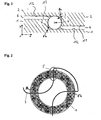
- FIG. 1 a schematic section through a part of a preferred embodiment of the sensor according to the invention is shown.
- An optical fiber 3 with a fiber core 4 is arranged between a first and second part or carrier part 1 and 2 comprising a carrier material of a sensor according to the invention and is preferably embedded between these.
- Obvious requirements for the substrate are robustness, mechanical rigidity, and ease of processing. Accordingly, a production would be advantageous for example of a metal or a metal alloy or a hard plastic. Preferred are brass, steel or ceramic.
- the fiber 3 is mechanically connected by means of a fastening 7 with the two parts 1 and 2 of the sensor.
- the attachment 7 may be, for example, that the fiber 3 is poured into a corresponding recess or groove within the parts 1 and 2.
- a suitable adhesive e.g. of epoxy resins.
- the attachment 7 may also have an elastic material, so that the optical fiber 3 can be clamped or pressed between the two parts 1 and 2.
- a thin bore is used as the guide for the optical fiber.
- the invention is based inter alia on the idea that transverse voltages in the transverse direction, ie in the case of Fig. 1 in the direction of the x and y axes, and can preferably be distinguished from one another.
- a gap 6 between the first and second part at the position of the fiber 3 on an offset is suitable to initiate the forces acting specifically in the fiber 3 and so implement in certain or desired voltage pattern within the fiber.
- the waveguide is applied directly to a substrate.
- the introduction of force is then recalculated via glides or shear stresses.
- the waveguide guide preferably corresponds to the in Fig. 2 shown. It can then be dispensed with the edge structure.
- the introduced strains are then as mentioned partially glides, which are visually evaluated.
- the in Fig. 1 shown cross-strain structure ie, a structure which is suitable to initiate the forces acting specifically in the fiber 3 and so in certain or desired measurable voltage pattern to implement within the fiber, preferably designed so that the first part 1 and the second part 2 of the sensor respectively have one or more edge (s) or paragraphs 8a, 8b.
- the two parts 1 and 2 are then, as in Fig. 1 indicated, so arranged or connected to each other, that essentially two corresponding edges 8a and 8b create a space or cavity for receiving the fiber 3.
- the two parts 1 and 2 are arranged so that at least partially a contact-free area 6 is formed.
- this non-contact region preferably has an offset or a step.
- the parts 1 and 2 have mutually aligned or correspondingly executed sides, which are suitable for receiving at least one fiber 3 with at least one means 5 having section between them.
- the corresponding surfaces of parts 1 and 2 have matched contours or geometries.
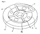
- Fig. 2 and 3 show a schematic plan view of a preferred first part 1 of a sensor according to the invention together with an optical fiber 3 and four means 5 or 5a, 5b, 5c and 5d for detecting deformations and / or stresses, here preferably Fiber Bragg gratings.
- the corresponding second part 2 of the sensor is not shown. Since a means for detecting deformations and / or stress or fiber Bragg gratings can detect two expansion components and one is generally interested in a total of six independent variables, the sensor should have at least three means for detecting deformations and / or stresses or Fiber Bragg gratings include. Further means for detecting deformations and / or stresses or grids, as in the example of Fig.
- a fourth can increase the precision of the measurement.
- a temperature or a temperature gradient can be compensated within the structure.
- fiber Bragg gratings as means for detecting deformations and / or stresses will be referred to. It will be understood, however, that other suitable means may be preferred.
- the fiber Bragg gratings must be arranged using three gratings so that force or moment components can be measured in all three spatial directions.
- an arrangement on two mutually perpendicular or substantially vertical axes as in FIG Fig. 2 and 3 shown.
- a symmetrical arrangement with 120 ° between the grids is conceivable.
- the axis perpendicular to the drawing plane ( Fig. 2 . 3 ) must not be operated as already stated, since each grid provides two measuring directions, of which an advantageous way just perpendicular to the plane of the drawing.
- the fibers or the sections of the fiber (s) having the means for detecting deformations and / or stresses are arranged with their longitudinal axis aligned with each other in a substantially radial direction.
- the fiber (s) or sections are / are arranged essentially in one plane.
- the respective transverse expansion structures ie, for example, the edges 6 according to this arrangement in the two parts 1 and 2 are preferably provided.
- the edges 8b of the first part 1 are mounted on alternating sides of the fiber sections.
- the transverse strain structures preferably have an alternating symmetry.
- FIG Fig. 3 Another embodiment of the edges is shown in FIG Fig. 3 to see.
- Fig. 4 shown corresponding perspective view shows the three-dimensional structure of the edges 8b even more clearly.
- the fiber conventional commercially available optical fibers can be used. Depending on the arrangement, it may be advantageous if the fiber used has a small allowable radius of curvature. Further, it is expedient to use a polarization maintaining fiber to facilitate the evaluation of the detected signal. Particularly suitable are fibers whose optical properties vary greatly under deformation or stress, for example polymer fiber or polymer-based fibers and for high-temperature applications, in particular sapphire fibers.
- a preferred assembled sensor according to the invention in which the first part 1 and the second part 2 firmly enclose the optical fiber 3 at least in the sections.
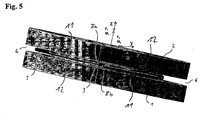
- the two parts are connected substantially only via the optical fiber 3 or the connecting or fastening material 7 surrounding them, while the two parts are otherwise connected by means of a gap 6, for example of the type shown in FIG Fig. 1 or Fig. 5 are shown separated from each other. This ensures that all forces or moments occurring between the two parts are transmitted to the optical fiber 3 and there lead to corresponding deformations or stresses.
- the two parts have additional connecting elements in order to achieve greater stability.
- these connecting elements should preferably be elastic, so that at least some of the forces or moments that occur are transferred to the optical fiber despite these connections.
- each two transverse strain structures 8 (8a, 8b) are spaced apart in the same direction along the fiber oriented.
- two of the transverse strain structures 8 (8a, 8b) oriented in substantially the same direction along the fiber are each disposed on different or opposite sides of the fiber.
- the four offset by 90 ° transverse expansion structures 8 seen in or against the counterclockwise direction are arranged alternately on each of the other side of the fiber 3.
- parts 1 and 2 optionally have additional fasteners for the corresponding application.
- additional fasteners for the corresponding application.
- threads, holes, pins, grooves, flanges or similar devices may be provided to connect the sensor according to the invention with other devices or devices or to attach it to this.
- the sensor may additionally include a light source, not shown, and a corresponding detector.
- a control unit such as a suitably programmed PC, can be provided, which controls the individual components and evaluates the detected signals, i. calculated from the measured spectrum, the forces or moments.
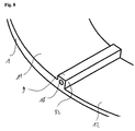
- Fig. 6 shows a perspective view of a first part of another preferred embodiment of a sensor according to the invention.
- the transverse expansion structure 8 described above has ribs or strips 9, each having a guide bore or opening 10 into which the optical fiber 3 can be inserted.
- Fig. 7 represents a corresponding sensor from the first and second part in the side view.
- an offset or an edge 8b is preferably provided in the region of the rib or strip 9.
- the second part 2 of the sensor preferably has corresponding edges 8a which form a transverse expansion structure in engagement with the ribs 9.
- the formation of the edges 8a and 8b in this preferred embodiment corresponds to the embodiments described above, wherein the space or cavity formed by two corresponding edges is filled by the rib or strip 9 for receiving the fiber 3.
- the part 1 preferably has a raised area 11, which forms an edge 8b opposite a recessed or recessed area 12.
- a raised area forms two edges 8b together with two recessed areas 12, or a recessed area 12 forms two edges 8b together with two raised areas.
- This structure is also preferable in the embodiment according to FIG Fig. 1 to 7 present, as the figures can be seen.
- a rib 9 is formed in the area of the edges, ie at the transition from a raised 11 to a recessed area 12, in the embodiment according to Fig. 6 to 8 a rib 9 is formed. This is also the detailed view according to Fig. 8 refer to.
- the fiber which has a small diameter of preferably about 70 to 90 microns, and preferably about 80 microns, initially coppered with a copper jacket of preferably about 40 to 60 microns and preferably 50 microns thick. Subsequently, the copper-plated fiber is threaded into the column or drilled guide holes, heated, and then soldered to the guide hole by adding solder.
- a sensor according to the invention preferably has a diameter of about 10 to 30 mm, and preferably about 20 mm.
- the sensor according to the invention has several advantages over conventional sensors. On the one hand, it can be produced relatively easily and inexpensively using already known standard methods. Its construction is simple and robust compared to conventional sensors. For example, it can be made significantly stiffer than previously known sensors. Nevertheless, it allows measurements of great precision. A particular advantage is its small size and / or planar design: Since the individual sensor elements can be arranged in one plane and at the same time can be made relatively thin, a sensor is provided which reduces significantly in one dimension Has dimensions compared to conventional sensors. Nevertheless, the sensor according to the invention can detect forces and moments perpendicular to its planar shape. A significant extension of the spatial arrangement in the direction of the force to be measured is not required in particular. Thus, the sensor according to the invention is flexible and suitable for special applications with high requirements for miniaturization.
Landscapes
- Physics & Mathematics (AREA)
- General Physics & Mathematics (AREA)
- Length Measuring Devices By Optical Means (AREA)
- Force Measurement Appropriate To Specific Purposes (AREA)
- Optical Transform (AREA)
Priority Applications (3)
| Application Number | Priority Date | Filing Date | Title |
|---|---|---|---|
| EP07021502A EP2056086A1 (fr) | 2007-11-05 | 2007-11-05 | Capteur effort-moment |
| PCT/EP2008/009318 WO2009059754A1 (fr) | 2007-11-05 | 2008-11-05 | Capteur de forces/moments |
| US12/774,383 US20100272384A1 (en) | 2007-11-05 | 2010-05-05 | Force-moment sensor |
Applications Claiming Priority (1)
| Application Number | Priority Date | Filing Date | Title |
|---|---|---|---|
| EP07021502A EP2056086A1 (fr) | 2007-11-05 | 2007-11-05 | Capteur effort-moment |
Publications (1)
| Publication Number | Publication Date |
|---|---|
| EP2056086A1 true EP2056086A1 (fr) | 2009-05-06 |
Family
ID=39156558
Family Applications (1)
| Application Number | Title | Priority Date | Filing Date |
|---|---|---|---|
| EP07021502A Withdrawn EP2056086A1 (fr) | 2007-11-05 | 2007-11-05 | Capteur effort-moment |
Country Status (3)
| Country | Link |
|---|---|
| US (1) | US20100272384A1 (fr) |
| EP (1) | EP2056086A1 (fr) |
| WO (1) | WO2009059754A1 (fr) |
Cited By (2)
| Publication number | Priority date | Publication date | Assignee | Title |
|---|---|---|---|---|
| KR20150085771A (ko) * | 2014-01-16 | 2015-07-24 | 더 보잉 컴파니 | 패스너 프리로드의 광학적 측정 |
| CN113607313A (zh) * | 2021-07-09 | 2021-11-05 | 武汉理工大学 | 基于c形梁的层积式光纤光栅六维力-力矩传感器 |
Families Citing this family (8)
| Publication number | Priority date | Publication date | Assignee | Title |
|---|---|---|---|---|
| KR101960839B1 (ko) * | 2012-09-04 | 2019-03-22 | 삼성전자주식회사 | 힘 센싱 장치 및 힘 센싱 장치의 동작 방법 |
| DE102014100653B4 (de) * | 2014-01-21 | 2016-01-21 | fos4X GmbH | Schienenmesssystem |
| SI3708990T1 (sl) * | 2019-03-14 | 2022-06-30 | Thales Management & Services Deutschland Gmbh | Enota optičnega vlakenskega senzorja, optični merilni sistem, naprava za štetje osi, postopek za štetje osi |
| IT201900008898A1 (it) * | 2019-06-13 | 2020-12-13 | Freni Brembo Spa | Metodo e sistema per determinare una coppia di frenata, mediante rilevazione effettuata con sensori fotonici ad un’interfaccia di fissaggio tra un corpo di pinza freno e un rispettivo supporto |
| CN114216594B (zh) * | 2021-12-01 | 2022-11-11 | 上海交通大学 | 一种机械手 |
| DE202022103426U1 (de) | 2022-06-20 | 2023-10-09 | Peiner Umformtechnik Gesellschaft mit beschränkter Haftung | Sensoreinrichtung zum Erfassen einer Vorspannkraft einer Schraubenverbindung |
| DE202022103425U1 (de) | 2022-06-20 | 2023-10-09 | Peiner Umformtechnik Gesellschaft mit beschränkter Haftung | Sensoreinrichtung zum Erfassen einer Vorspannkraft einer Schraubenverbindung |
| CN115638909B (zh) * | 2022-11-04 | 2025-06-17 | 之江实验室 | 一种基于聚合物光纤结敏感结构与硅胶基底的硬度传感器 |
Citations (6)
| Publication number | Priority date | Publication date | Assignee | Title |
|---|---|---|---|---|
| WO2000028294A1 (fr) * | 1998-11-11 | 2000-05-18 | European Community, Represented By Commission Of The European Communities | Capteur de contrainte avec reseaux de bragg a fibre optique |
| EP1403628A2 (fr) * | 1995-09-19 | 2004-03-31 | Japan Electronics Industry, Ltd. | Capteur de contraintes pour mesurer les forces exercées sur une roue de véhicule |
| DE69629340T2 (de) * | 1995-04-12 | 2005-02-10 | Giat Industries | Wandler zum messen der torsion zwischen zwei gekoppelten mechanischen teilen und verfahren zur fertigung des wandlers |
| US20060104561A1 (en) * | 2004-11-12 | 2006-05-18 | Gennadii Ivtsenkov | Fiber optic strain sensor and associated data acquisition system |
| EP1726473A1 (fr) * | 2005-05-25 | 2006-11-29 | Siemens Aktiengesellschaft | Dispositif pour mesurer une force et méthode pour la détermination d'une force transversale |
| US20070051187A1 (en) * | 2005-09-06 | 2007-03-08 | The Timken Company | Load-sensing bearing |
Family Cites Families (1)
| Publication number | Priority date | Publication date | Assignee | Title |
|---|---|---|---|---|
| US6931188B2 (en) * | 2003-02-21 | 2005-08-16 | Weatherford/Lamb, Inc. | Side-hole cane waveguide sensor |
-
2007
- 2007-11-05 EP EP07021502A patent/EP2056086A1/fr not_active Withdrawn
-
2008
- 2008-11-05 WO PCT/EP2008/009318 patent/WO2009059754A1/fr not_active Ceased
-
2010
- 2010-05-05 US US12/774,383 patent/US20100272384A1/en not_active Abandoned
Patent Citations (6)
| Publication number | Priority date | Publication date | Assignee | Title |
|---|---|---|---|---|
| DE69629340T2 (de) * | 1995-04-12 | 2005-02-10 | Giat Industries | Wandler zum messen der torsion zwischen zwei gekoppelten mechanischen teilen und verfahren zur fertigung des wandlers |
| EP1403628A2 (fr) * | 1995-09-19 | 2004-03-31 | Japan Electronics Industry, Ltd. | Capteur de contraintes pour mesurer les forces exercées sur une roue de véhicule |
| WO2000028294A1 (fr) * | 1998-11-11 | 2000-05-18 | European Community, Represented By Commission Of The European Communities | Capteur de contrainte avec reseaux de bragg a fibre optique |
| US20060104561A1 (en) * | 2004-11-12 | 2006-05-18 | Gennadii Ivtsenkov | Fiber optic strain sensor and associated data acquisition system |
| EP1726473A1 (fr) * | 2005-05-25 | 2006-11-29 | Siemens Aktiengesellschaft | Dispositif pour mesurer une force et méthode pour la détermination d'une force transversale |
| US20070051187A1 (en) * | 2005-09-06 | 2007-03-08 | The Timken Company | Load-sensing bearing |
Non-Patent Citations (3)
| Title |
|---|
| CHEN-CHUN YE ET AL: "A polarization-maintaining fibre Bragg grating interrogation system for multi-axis strain sensing; A PM FBG interrogation system", MEASUREMENT SCIENCE AND TECHNOLOGY, IOP, BRISTOL, GB LNKD- DOI:10.1088/0957-0233/13/9/310, vol. 13, no. 9, 1 September 2002 (2002-09-01), pages 1446 - 1449, XP020063606, ISSN: 0957-0233 * |
| DATABASE COMPENDEX [online] ENGINEERING INFORMATION, INC., NEW YORK, NY, US; September 2002 (2002-09-01), YE C-C ET AL: "A polarization-maintaining fibre Bragg grating interrogation system for multi-axis strain sensing", Database accession no. E2002417128054 * |
| MEASUREMENT SCIENCE AND TECHNOLOGY SEPTEMBER 2002 INSTITUTE OF PHYSICS PUBLISHING GB, vol. 13, no. 9, September 2002 (2002-09-01), pages 1446 - 1449, DOI: 10.1088/0957-0233/13/9/310 * |
Cited By (5)
| Publication number | Priority date | Publication date | Assignee | Title |
|---|---|---|---|---|
| KR20150085771A (ko) * | 2014-01-16 | 2015-07-24 | 더 보잉 컴파니 | 패스너 프리로드의 광학적 측정 |
| JP2015135326A (ja) * | 2014-01-16 | 2015-07-27 | ザ・ボーイング・カンパニーTheBoeing Company | 留具のプリロードの光学的測定 |
| EP2899522A3 (fr) * | 2014-01-16 | 2015-08-19 | The Boeing Company | Mesure optique de précharge d'attache |
| US9492901B2 (en) | 2014-01-16 | 2016-11-15 | The Boeing Company | Optical measurement of fastener preload |
| CN113607313A (zh) * | 2021-07-09 | 2021-11-05 | 武汉理工大学 | 基于c形梁的层积式光纤光栅六维力-力矩传感器 |
Also Published As
| Publication number | Publication date |
|---|---|
| WO2009059754A1 (fr) | 2009-05-14 |
| US20100272384A1 (en) | 2010-10-28 |
Similar Documents
| Publication | Publication Date | Title |
|---|---|---|
| WO2009059754A1 (fr) | Capteur de forces/moments | |
| DE102007008464B4 (de) | Optischer Dehnungsmessstreifen | |
| DE102013101432B4 (de) | Faseroptischer Beschleunigungssensor mit Hebel | |
| DE2855746C3 (de) | Piezoelektrischer Dehnungsaufnehmer | |
| EP2711676A2 (fr) | Capteur de force à fibre optique, dispositif de mesure de force et cathéter | |
| EP3158296B1 (fr) | Capteur à fibre optique ainsi que procédé pour sa fabrication et son utilisation | |
| EP3559681B1 (fr) | Capteur d'accélération à fibre optique avec bras de levier | |
| CH661985A5 (de) | Verfahren zur kraftmessung mit hilfe der spannungsinduzierten doppelbrechung in einem monomode-lichtleiter und messanordnung zur durchfuehrung des verfahrens. | |
| DE112014004544T5 (de) | FBG-Sensor zur Messung maximaler Dehnung, Herstellungsverfahren und Verwendungsverfahren | |
| DE102010016837A1 (de) | Faser-Bragg-Gitter-Messsystem | |
| DE102005030753A1 (de) | Optischer Dehnungsmessstreifen | |
| DE19939583A1 (de) | Bragg-Gitter-Vorrichtung zum Messen einer mechanischen Kraft sowie Anwendung und Verfahren zum Betrieb der Vorrichtung | |
| DE102004008432B4 (de) | Dehnungsmessstreifen zur Erfassung von Dehnungen oder Stauchungen an Verformungskörpern | |
| DE102012214441B4 (de) | Messverfahren | |
| DE3418247A1 (de) | Durchbiegungsmesser | |
| WO2018141501A1 (fr) | Dispositif de détection à fibre optique et procédé pour faire fonctionner un dispositif de détection à fibre optique | |
| DE102008020247B4 (de) | Messanordnung mit einem Faser-Bragg-Gitter zur Erfassung von Dehnungen und/oder Temperaturen | |
| EP2892791B1 (fr) | Procédé de mesure de la tension d'une courroie | |
| DE2617987C2 (de) | Meßvorrichtung mit Dehnungsmeßstreifen | |
| DE102005030751A1 (de) | Optischer Dehnungsmessstreifen | |
| DE10238862B4 (de) | Messtechnische Anordnung zur Prüfung von Werkstücken sowie Verfahren zur messtechnischen Instrumentierung von Werkstücken | |
| DE102017130761A1 (de) | System und Verfahren zur Überwachung des Anpressdrucks einer kraft- und/oder formschlüssigen Verbindung | |
| DE102012104884A1 (de) | Faseroptischer Kraftaufnehmer und optisches Messverfahren | |
| EP3489647B1 (fr) | Capteur de force | |
| DE69422899T2 (de) | Fiberoptischer polarimetrischer Verschiebungssensor und assoziiertes Messverfahren |
Legal Events
| Date | Code | Title | Description |
|---|---|---|---|
| PUAI | Public reference made under article 153(3) epc to a published international application that has entered the european phase |
Free format text: ORIGINAL CODE: 0009012 |
|
| AK | Designated contracting states |
Kind code of ref document: A1 Designated state(s): AT BE BG CH CY CZ DE DK EE ES FI FR GB GR HU IE IS IT LI LT LU LV MC MT NL PL PT RO SE SI SK TR |
|
| AX | Request for extension of the european patent |
Extension state: AL BA HR MK RS |
|
| 17P | Request for examination filed |
Effective date: 20091028 |
|
| AKX | Designation fees paid |
Designated state(s): AT BE BG CH CY CZ DE DK EE ES FI FR GB GR HU IE IS IT LI LT LU LV MC MT NL PL PT RO SE SI SK TR |
|
| 17Q | First examination report despatched |
Effective date: 20100914 |
|
| STAA | Information on the status of an ep patent application or granted ep patent |
Free format text: STATUS: THE APPLICATION IS DEEMED TO BE WITHDRAWN |
|
| 18D | Application deemed to be withdrawn |
Effective date: 20130601 |