EP2056307B1 - Dispositif de déclenchement destiné au déclenchement de sécurités contre le vol pouvant être déclenchées de manière magnétique - Google Patents
Dispositif de déclenchement destiné au déclenchement de sécurités contre le vol pouvant être déclenchées de manière magnétique Download PDFInfo
- Publication number
- EP2056307B1 EP2056307B1 EP08163674A EP08163674A EP2056307B1 EP 2056307 B1 EP2056307 B1 EP 2056307B1 EP 08163674 A EP08163674 A EP 08163674A EP 08163674 A EP08163674 A EP 08163674A EP 2056307 B1 EP2056307 B1 EP 2056307B1
- Authority
- EP
- European Patent Office
- Prior art keywords
- magnet
- release device
- segmented
- magnetic core
- magnetised
- Prior art date
- Legal status (The legal status is an assumption and is not a legal conclusion. Google has not performed a legal analysis and makes no representation as to the accuracy of the status listed.)
- Active
Links
Images



Classifications
-
- H—ELECTRICITY
- H01—ELECTRIC ELEMENTS
- H01F—MAGNETS; INDUCTANCES; TRANSFORMERS; SELECTION OF MATERIALS FOR THEIR MAGNETIC PROPERTIES
- H01F7/00—Magnets
- H01F7/02—Permanent magnets [PM]
- H01F7/0273—Magnetic circuits with PM for magnetic field generation
- H01F7/0278—Magnetic circuits with PM for magnetic field generation for generating uniform fields, focusing, deflecting electrically charged particles
-
- E—FIXED CONSTRUCTIONS
- E05—LOCKS; KEYS; WINDOW OR DOOR FITTINGS; SAFES
- E05B—LOCKS; ACCESSORIES THEREFOR; HANDCUFFS
- E05B73/00—Devices for locking portable objects against unauthorised removal; Miscellaneous locking devices
- E05B73/0017—Anti-theft devices, e.g. tags or monitors, fixed to articles, e.g. clothes, and to be removed at the check-out of shops
-
- H—ELECTRICITY
- H01—ELECTRIC ELEMENTS
- H01F—MAGNETS; INDUCTANCES; TRANSFORMERS; SELECTION OF MATERIALS FOR THEIR MAGNETIC PROPERTIES
- H01F7/00—Magnets
- H01F7/02—Permanent magnets [PM]
- H01F7/0205—Magnetic circuits with PM in general
- H01F7/021—Construction of PM
-
- Y—GENERAL TAGGING OF NEW TECHNOLOGICAL DEVELOPMENTS; GENERAL TAGGING OF CROSS-SECTIONAL TECHNOLOGIES SPANNING OVER SEVERAL SECTIONS OF THE IPC; TECHNICAL SUBJECTS COVERED BY FORMER USPC CROSS-REFERENCE ART COLLECTIONS [XRACs] AND DIGESTS
- Y10—TECHNICAL SUBJECTS COVERED BY FORMER USPC
- Y10T—TECHNICAL SUBJECTS COVERED BY FORMER US CLASSIFICATION
- Y10T24/00—Buckles, buttons, clasps, etc.
- Y10T24/32—Buckles, buttons, clasps, etc. having magnetic fastener
-
- Y—GENERAL TAGGING OF NEW TECHNOLOGICAL DEVELOPMENTS; GENERAL TAGGING OF CROSS-SECTIONAL TECHNOLOGIES SPANNING OVER SEVERAL SECTIONS OF THE IPC; TECHNICAL SUBJECTS COVERED BY FORMER USPC CROSS-REFERENCE ART COLLECTIONS [XRACs] AND DIGESTS
- Y10—TECHNICAL SUBJECTS COVERED BY FORMER USPC
- Y10T—TECHNICAL SUBJECTS COVERED BY FORMER US CLASSIFICATION
- Y10T24/00—Buckles, buttons, clasps, etc.
- Y10T24/50—Readily interlocking, two-part fastener requiring either destructive or tool disengagement
Definitions
- the present invention describes a release device for releasing magnetically releasable anti-theft devices consisting of a release-side cover plate and a support plate or support base plate between which serving to solve the anti-theft permanent magnet elements are arranged.
- a release device for solving theft is in the EP0047264 discloses wherein a ring magnet and a magnetic disk are vertically spaced from one another, forming a plurality of horizontally lying layers, and vertically bounded by a cover plate and a bottom plate.
- the ring magnet and the magnetic disk have different strength magnetic field strengths and can be made of different materials.
- the release device has a sandwich-like shape in the vertical direction, wherein the Magnetic disc is located on the bottom plate and is surrounded by a steel disc, which also lies on the bottom plate. On the steel disk, the ring magnet is vertically spaced from the magnetic disk.
- the magnetic field lines are mainly vertical and thus axially in the direction of the magnetic disk, so that a force component acts mainly in the vertical direction.
- the described structure has a sandwich-like shape in the vertical direction, whereby a corresponding height results.
- a corresponding height results.
- the height of the entire release device is further increased. Since the anti-theft device must be brought close to the strongly magnetized magnetic disk, so that the magnetic field is sufficiently large, holes are provided, the diameter of the anti-theft devices must be sufficiently large. With this structure, this does not guarantee that all Theft locks are removable because the diameter of the anti-theft devices vary.
- the present invention has for its object to provide a device for solving the magnetically releasable anti-theft devices, which has a vertical single-layer and flat structure, which is simple and easy to produce material and particularly space-saving next to the cash register in a table top or the like can be lowered.
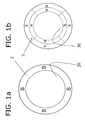
- a release device 1 which is based on a Halbach array, which has a strong magnetic top 10 and a weak magnetic bottom 11.
- a Halbach array has the special property that due to the suitable arrangement of the permanent magnet elements the magnetic field is concentrated on the strongly magnetic upper side 10, while on the upper side 10 opposite underside 11 almost no magnetic field lines emerge from the Halbach array, whereby only one weak magnetic field near the bottom 11 is measurable.
- the release device 1 consists of a plurality of permanent magnet elements, which are adjacent to each other and embedded in one another in a plane, wherein the magnetization directions of directly adjacent permanent magnet elements are arranged in mutually approximately perpendicular planes.
- the magnetization direction of the individual permanent magnet elements is, as usual in physics, indicated by an arrow whose arrowhead points to the magnetic north pole of the considered permanent magnet element. According to this convention, a representation of the magnetization directions of the individual permanent magnet elements is obtained, as in FIG FIG. 3 indicated.
- the respective north magnetic poles and south magnetic poles are designated N and S in the figures.
- the release device 1 for releasing magnetically releasable anti-theft devices has a cover plate 6 which covers the release side on the highly magnetic top 10.
- the opposite bottom 11 is covered by one of the bracket or the support serving base plate 5.
- Between the cover plate 6 and the bottom plate 5 is at least one circumferentially closed frame magnet 2, which has a first recess 20 in which further elements can be accommodated.
- FIG. 1a While in FIG. 1a an annular frame magnet 2 is shown, shows FIG. 2 a rectangular frame magnet 2.
- the magnetization direction of the at least one frame magnet 2 is approximately perpendicular to the paper plane and thus approximately parallel to the central axis of the annular or rectangular frame magnet 2.
- the connecting line between the north pole and south pole is oriented approximately perpendicular to the paper plane, the north pole to Bottom 11 of the release device 1 has.
- a segmented magnet 3 is inserted flush with the frame magnet 2, the magnetization direction is aligned approximately perpendicular to the magnetization direction of the frame magnet 2 and thus is approximately parallel to the paper plane.
- the frame magnet 2 and the segmented magnet 3 are located in the same plane by the engagement of the segmented magnet 3, resulting in a flat structure.
- the segmented magnet 3 comprises a plurality of segments 31 and has a second recess 30.
- the possible two embodiments shown here show segmented magnets 3 each with four segments 31, the south poles of the individual segments 31 abutting against the inner wall of the first recess 20 of the frame magnet 2, while the north poles of the individual segments 31 are facing the second recess 30.
- a magnetic core 4 is fastened, again in the same plane in which the frame magnet 2 and the segmented magnet 3 are located.
- the magnetic core 4 has a magnetization direction approximately parallel to its central axis, wherein the vector arrow of the magnetization direction to the top 10 of the release device 1 shows.
- the magnetic north pole of the magnetic core 4 thus has, in contrast to the frame magnet 2 in the direction of the upper side 10 of the release device.
- the first recess 20 and the second recess 30 should each be mounted centrally in the frame magnet 2 and in the segmented magnet 3. Optimum results were achieved with the ring-shaped frame magnet 2 and a central first recess 20 in the form of a cylindrical bore and a central second recess 30 in the segmented magnet 3, which in the FIGS. 1a and 1b are shown.
- the problem is the arrangement and attachment of the permanent magnet elements, since the same magnetic poles of adjacent permanent magnet elements partially overlap and therefore sometimes very large repulsive forces occur.
- the frame magnet 2, the segmented magnet 3 and the magnetic core 4 can be glued to the bottom plate 5 and connected to it inseparably.
- the individual segments 31 are also glued in the first recess 20 to the inner surfaces of the frame magnet 2 for stabilization.
- the cover plate 6 is permanently attached to the top 10, so that a compact single-layer release device 1 results from permanent magnet elements, for example, in a Table top can be inserted.
- two components epoxy resins are used for bonding the individual permanent magnet elements.
- the use of high magnetic materials, high remanence magnetic materials such as samarium cobalt, neodymium-iron-boron and aluminum-nickel-cobalt makes it possible to reduce the thickness of the release device 1, thereby providing dissolvers 1 in disk shapes of 15 mm to 10 mm are possible.
- the cover plate 6, as well as the bottom plate 5 are made of chrome steel and are used in addition to design purposes, the protection of the permanent magnet elements.
- neodymium-iron boron is used for the dissolution devices disclosed herein.
- the vertical height of either the frame magnet 2 or the segmented magnet 3 is selected to be higher than the structural height of the magnetic core 4 and thus the magnetic core 4 in the direction of the top 10 is surmounted by the other permanent magnet elements, creating a well on the highly magnetic Top 10, whereby the magnetic field on the top 10 is still increased by about 10% to 20% compared to the planar design.
- segmented magnet 3 consisting of four segments 31 has hitherto been described so far in a preferred embodiment, it is also possible for only one annular segment 31 to form the magnet 3. In order to produce a release device according to the invention, the number of segments 31 must be at least one.
Landscapes
- Physics & Mathematics (AREA)
- Electromagnetism (AREA)
- Engineering & Computer Science (AREA)
- Power Engineering (AREA)
- Burglar Alarm Systems (AREA)
- Lubricants (AREA)
Claims (9)
- Dispositif de détachement (1) pour le détachement de sécurités antivol détachables de façon magnétique comprenant une plaque de recouvrement (6) côté détachement et une plaque de fond (5) servant au maintien ou au support, entre lesquelles sont disposés des éléments à aimant permanent servant au détachement de la sécurité antivol,
caractérisé en ce que
un aimant-cadre (2) fermé sur le pourtour est magnétisé dans le sens axial et présente un premier évidement (20), dans lequel
est disposé un aimant (3) segmenté se présentant sous la forme d'au moins un segment (31) magnétisé dans le sens radial, le ou les segment(s) (31) libérant un second évidement (30), dans lequel est emboîté un noyau (4) magnétique magnétisé dans le sens axial, de sorte que le dispositif de détachement représente un agencement monocouche dans le sens vertical et plat d'éléments à aimant permanent. - Dispositif de détachement selon la revendication 1, caractérisé en ce que l'aimant-cadre (2), l'aimant (3) segmenté et le noyau (4) magnétique sont fixés de façon indétachable sur la plaque de fond (5).
- Dispositif de détachement selon la revendication 1, caractérisé en ce que l'aimant-cadre (2), l'aimant (3) segmenté et le noyau (4) magnétique sont conçus en forme de disque circulaire.
- Dispositif de détachement selon la revendication 1, caractérisé en ce que le premier évidement (20) et le second évidement (30) sont des percements avec des surfaces de section circulaires.
- Dispositif de détachement selon la revendication 1, caractérisé en ce que la plaque de recouvrement (6) dépasse des dimensions radiales de l'aimant-cadre (2), le dispositif de détachement (1), emboîté dans un évidement, pouvant être fixé par complémentarité de formes.
- Dispositif de détachement selon la revendication 1, caractérisé en ce que la hauteur de structure de l'aimant-cadre (2) est choisie plus grande que les hauteurs de structure de l'aimant (3) segmenté et du noyau (4) magnétique.
- Dispositif de détachement selon la revendication 1, caractérisé en ce que la hauteur de structure de l'aimant (3) segmenté est choisie plus grande que la hauteur de structure de l'aimant-cadre (2) et du noyau (4) magnétique.
- Utilisation d'un dispositif de Halbach dans un dispositif de détachement pour le détachement de sécurités antivol maintenues de façon magnétique,
comprenant un aimant-cadre (2) fermé sur le pourtour et magnétisé dans le sens axial, qui présente un premier évidement (20), dans lequel est disposé un aimant (3) segmenté sous la forme d'au moins un segment (31) magnétisé dans le sens radial, le ou les segment(s) (31) libérant un second évidement (30), dans lequel est emboîté un noyau (4) magnétique magnétisé dans le sens axial, le dispositif de détachement présentant un agencement vertical et plat d'aimants permanents. - Utilisation selon la revendication 8 d'un dispositif de détachement selon la revendication 6, caractérisé en ce que le dispositif de Halbach est formé par
l'aimant-cadre (2),
l'aimant (3) segmenté sous la forme d'au moins un segment (31) magnétisé dans le sens radial et
le noyau (4) magnétique,
à chaque fois des éléments voisins à aimant permanent étant magnétisés les uns par rapport aux autres et orientés en alternance dans des plans perpendiculaires entre eux.
Applications Claiming Priority (1)
| Application Number | Priority Date | Filing Date | Title |
|---|---|---|---|
| CH15182007 | 2007-10-01 |
Publications (2)
| Publication Number | Publication Date |
|---|---|
| EP2056307A1 EP2056307A1 (fr) | 2009-05-06 |
| EP2056307B1 true EP2056307B1 (fr) | 2010-12-22 |
Family
ID=40351793
Family Applications (1)
| Application Number | Title | Priority Date | Filing Date |
|---|---|---|---|
| EP08163674A Active EP2056307B1 (fr) | 2007-10-01 | 2008-09-04 | Dispositif de déclenchement destiné au déclenchement de sécurités contre le vol pouvant être déclenchées de manière magnétique |
Country Status (4)
| Country | Link |
|---|---|
| US (1) | US7921524B2 (fr) |
| EP (1) | EP2056307B1 (fr) |
| AT (1) | ATE492892T1 (fr) |
| DE (1) | DE502008002064D1 (fr) |
Families Citing this family (18)
| Publication number | Priority date | Publication date | Assignee | Title |
|---|---|---|---|---|
| US8054185B2 (en) * | 2008-12-17 | 2011-11-08 | Sensormatic Electronics, LLC | Optimization of the field profile on a high field strength magnetic detacher |
| US8305177B2 (en) * | 2009-01-12 | 2012-11-06 | Dexter Magnetic Technologies, Inc. | Multi function magnetic decoupler |
| US8615853B2 (en) * | 2010-10-12 | 2013-12-31 | Donald P Rathbun | Multipole magnet for holding items to clothing |
| TWI384510B (zh) * | 2010-11-12 | 2013-02-01 | Ind Tech Res Inst | 均勻磁場產生設備及其磁場產生單元 |
| US8847762B2 (en) * | 2011-06-23 | 2014-09-30 | Tyco Fire & Security Gmbh | Security system tag magnetic clutch and method |
| US20130002382A1 (en) * | 2011-06-28 | 2013-01-03 | Bo Zhang | Magnetic cup assembly holding device with low magnetic leakage field |
| US20130305497A1 (en) * | 2012-05-16 | 2013-11-21 | Ronald E. Coman | Permanent magnet panel fastener |
| CN103915233B (zh) * | 2013-01-05 | 2017-02-08 | 江苏多维科技有限公司 | 一种适用于角度磁编码器的永磁体 |
| US20150325352A1 (en) * | 2014-05-07 | 2015-11-12 | Anker Technology Co., Limited | Magnet fixed device and an electronic device having the same or an accessory having the same |
| US11178930B2 (en) | 2014-08-01 | 2021-11-23 | Carter J. Kovarik | Helmet for reducing concussive forces during collision and facilitating rapid facemask removal |
| US10092057B2 (en) | 2014-08-01 | 2018-10-09 | Carter J. Kovarik | Helmet for reducing concussive forces during collision and facilitating rapid facemask removal |
| DE102015104888B4 (de) * | 2015-03-30 | 2018-07-05 | Jopp Holding GmbH | Anordnung eines Magnetelements mit Lagesensor zur Positionserkennung an einem rotierbaren Maschinenelement |
| CN105446428A (zh) * | 2015-12-18 | 2016-03-30 | 包头市英思特稀磁新材料有限公司 | 一种带有海尔贝克磁组件的键盘 |
| US11587706B2 (en) * | 2019-11-01 | 2023-02-21 | Christopher J. de la Rosa | Magnetic fastener |
| US11388996B2 (en) * | 2020-08-27 | 2022-07-19 | Hardware Resources, Inc. | Slidable cabinet pullout apparatus and method of use |
| US11896124B2 (en) | 2020-08-27 | 2024-02-13 | Hardware Resources, Inc. | Concealed apparatus for slidable pullout mounting and method of use |
| CN113481766B (zh) * | 2021-07-08 | 2025-03-11 | 西南交通大学 | 一种直线型Halbach阵列永磁轨道 |
| CN116794291B (zh) * | 2023-03-27 | 2025-12-05 | 陕西科技大学 | 一种组合式磁珠反应管及其使用方法 |
Family Cites Families (18)
| Publication number | Priority date | Publication date | Assignee | Title |
|---|---|---|---|---|
| US3899762A (en) * | 1974-10-03 | 1975-08-12 | Permag Magnetics Corp | Permanent magnetic structure |
| US4012813A (en) * | 1974-10-30 | 1977-03-22 | I. D. Engineering, Inc. | Anti-theft fastening device and tool for releasing same |
| US4339853A (en) * | 1980-03-04 | 1982-07-20 | Permag Corporation | Magnetic decoupler |
| US4531264A (en) * | 1983-07-27 | 1985-07-30 | Knogo Corporation | Theft detection system target fastener |
| US4527310A (en) * | 1983-07-22 | 1985-07-09 | I. D. Engineering, Inc. | Secure release apparatus for anti-theft fastening device |
| JPS60144190U (ja) * | 1984-03-03 | 1985-09-25 | 株式会社 横山精密工作所 | 万引防止装置における被検出体取付装置 |
| US6329895B1 (en) * | 1995-11-14 | 2001-12-11 | Albert Maurer | Releasing magnet for anti-theft devices for sales goods |
| WO1997031170A1 (fr) * | 1996-02-22 | 1997-08-28 | Albert Maurer | Systeme de protection contre le vol de marchandises et dispositif pour la mise en oeuvre dudit procede |
| US5865970A (en) * | 1996-02-23 | 1999-02-02 | Permag Corporation | Permanent magnet strucure for use in a sputtering magnetron |
| US5959520A (en) * | 1998-08-21 | 1999-09-28 | Dexter Magnetic Technologies, Inc. | Magnetic decoupler |
| US6084498A (en) * | 1998-08-21 | 2000-07-04 | Dexter Magnetic Technologies, Inc. | Magnetic decoupler |
| US7352268B2 (en) * | 2002-09-26 | 2008-04-01 | Engineering Matters, Inc. | High intensity radial field magnetic actuator |
| EP1711953A4 (fr) * | 2004-02-03 | 2014-12-03 | Astronautics Corp | Ensemble d'aimant permanent |
| US20080246573A1 (en) * | 2004-07-09 | 2008-10-09 | Souder James J | Field configurable magnetic array |
| JP2007040316A (ja) * | 2005-07-29 | 2007-02-15 | Smc Corp | 環状磁石およびそれを用いた流体圧シリンダ |
| US7352096B2 (en) * | 2005-08-05 | 2008-04-01 | Tom Dunn | Electro-motive machine using Halbach array |
| US7391327B2 (en) * | 2005-12-01 | 2008-06-24 | Sensormatic Electronics Corporation | Magnetic detacher with open access |
| US7486165B2 (en) * | 2006-10-16 | 2009-02-03 | Apple Inc. | Magnetic latch mechanism |
-
2008
- 2008-09-04 EP EP08163674A patent/EP2056307B1/fr active Active
- 2008-09-04 AT AT08163674T patent/ATE492892T1/de active
- 2008-09-04 DE DE502008002064T patent/DE502008002064D1/de active Active
- 2008-09-30 US US12/286,451 patent/US7921524B2/en not_active Expired - Fee Related
Also Published As
| Publication number | Publication date |
|---|---|
| DE502008002064D1 (de) | 2011-02-03 |
| EP2056307A1 (fr) | 2009-05-06 |
| US7921524B2 (en) | 2011-04-12 |
| ATE492892T1 (de) | 2011-01-15 |
| US20090083951A1 (en) | 2009-04-02 |
Similar Documents
| Publication | Publication Date | Title |
|---|---|---|
| EP2056307B1 (fr) | Dispositif de déclenchement destiné au déclenchement de sécurités contre le vol pouvant être déclenchées de manière magnétique | |
| DE60026426T2 (de) | Polstückeinheit für einen Magnet der bildgebenden magnetischen Resonanz | |
| DE3779715T2 (de) | Vorrichtung zur erzeugung eines magnetfeldes fuer rechnergesteuerte tomographie mittels magnetischer kernresonanz. | |
| DE69929006T2 (de) | Magnetfelderzeuger für die Magnetresonanzbildgebung und Verfahren zum Zusammenbau desselben | |
| DE69101923T2 (de) | Permanentmagnet für vorrichtung zur bilderzeugung mit magnetischer kernresonanz. | |
| DE2938809A1 (de) | Magnetisches schwebelager | |
| DE4143005A1 (de) | Magnetischer haftverschluss | |
| DE2611741A1 (de) | Magnetisch betaetigbare anzeigeeinrichtung | |
| EP0451375B1 (fr) | Transduceur électrodynamique pour ultrasons | |
| DE29823167U1 (de) | Warensicherungselement | |
| DE102007002065B4 (de) | Magnetvorrichtung, insbesondere zum Entriegeln von Sicherheitsanhängern an diebstahlgesicherten Waren | |
| DE4003212C2 (fr) | ||
| DE69131940T2 (de) | Apparat zur Erzeugung von Magnetfeldern für die Bildgebung mittels magnetischer Resonanz | |
| DE69229352T2 (de) | Magnetverschluss | |
| EP0247045A1 (fr) | Dispositif d'indication electromagnetique. | |
| DE899564C (de) | Magnetkopf fuer bandfoermige Magnettontraeger | |
| DE1500754A1 (de) | Einrichtung zur Daempfung mechanischer Schwingungen | |
| DE954348C (de) | Magnetanordnung fuer Drehspulmessgeraet mit Quadermagneten aus hochkoerzitivem Werkstoff und ring- oder ringstueckfoermigen Polschuhen innerhalb eines Rueckschlussringes | |
| DE4211872A1 (de) | Justiereinrichtung zur gegenseitigen Ausrichtung von miteinander zu verbauenden Flächenelementen | |
| DE3403073C2 (de) | Fernsteuerbare elektromagnetische alphanumerische Anzeigevorrichtung | |
| EP1443155A2 (fr) | Cloison amovible repliable et noed d'assemblage pour un tel cloison | |
| DE1466634C3 (de) | Bremsmagnet für Elektrizitätszähler | |
| DE1198851B (de) | Elektronischer Impulsgeber fuer einen Laeufer aufweisende Elektrizitaetszaehler | |
| DE102021118369A1 (de) | Vorrichtung zum Fixieren von Gegenständen, die aus ferromagnetischem Material bestehen oder dieses umfassen | |
| DE1195846B (de) | Mosaik-Schaltbild |
Legal Events
| Date | Code | Title | Description |
|---|---|---|---|
| PUAI | Public reference made under article 153(3) epc to a published international application that has entered the european phase |
Free format text: ORIGINAL CODE: 0009012 |
|
| AK | Designated contracting states |
Kind code of ref document: A1 Designated state(s): AT BE BG CH CY CZ DE DK EE ES FI FR GB GR HR HU IE IS IT LI LT LU LV MC MT NL NO PL PT RO SE SI SK TR |
|
| AX | Request for extension of the european patent |
Extension state: AL BA MK RS |
|
| 17P | Request for examination filed |
Effective date: 20091102 |
|
| 17Q | First examination report despatched |
Effective date: 20091201 |
|
| AKX | Designation fees paid |
Designated state(s): AT BE BG CH CY CZ DE DK EE ES FI FR GB GR HR HU IE IS IT LI LT LU LV MC MT NL NO PL PT RO SE SI SK TR |
|
| REG | Reference to a national code |
Ref country code: HK Ref legal event code: DE Ref document number: 1132581 Country of ref document: HK |
|
| GRAP | Despatch of communication of intention to grant a patent |
Free format text: ORIGINAL CODE: EPIDOSNIGR1 |
|
| GRAS | Grant fee paid |
Free format text: ORIGINAL CODE: EPIDOSNIGR3 |
|
| GRAA | (expected) grant |
Free format text: ORIGINAL CODE: 0009210 |
|
| AK | Designated contracting states |
Kind code of ref document: B1 Designated state(s): AT BE BG CH CY CZ DE DK EE ES FI FR GB GR HR HU IE IS IT LI LT LU LV MC MT NL NO PL PT RO SE SI SK TR |
|
| REG | Reference to a national code |
Ref country code: GB Ref legal event code: FG4D Free format text: NOT ENGLISH |
|
| REG | Reference to a national code |
Ref country code: CH Ref legal event code: EP |
|
| REG | Reference to a national code |
Ref country code: IE Ref legal event code: FG4D |
|
| REF | Corresponds to: |
Ref document number: 502008002064 Country of ref document: DE Date of ref document: 20110203 Kind code of ref document: P |
|
| REG | Reference to a national code |
Ref country code: DE Ref legal event code: R096 Ref document number: 502008002064 Country of ref document: DE Effective date: 20110203 |
|
| REG | Reference to a national code |
Ref country code: CH Ref legal event code: NV Representative=s name: SCHNEIDER FELDMANN AG PATENT- UND MARKENANWAELTE |
|
| REG | Reference to a national code |
Ref country code: NL Ref legal event code: VDEP Effective date: 20101222 |
|
| PG25 | Lapsed in a contracting state [announced via postgrant information from national office to epo] |
Ref country code: LT Free format text: LAPSE BECAUSE OF FAILURE TO SUBMIT A TRANSLATION OF THE DESCRIPTION OR TO PAY THE FEE WITHIN THE PRESCRIBED TIME-LIMIT Effective date: 20101222 |
|
| LTIE | Lt: invalidation of european patent or patent extension |
Effective date: 20101222 |
|
| PG25 | Lapsed in a contracting state [announced via postgrant information from national office to epo] |
Ref country code: LV Free format text: LAPSE BECAUSE OF FAILURE TO SUBMIT A TRANSLATION OF THE DESCRIPTION OR TO PAY THE FEE WITHIN THE PRESCRIBED TIME-LIMIT Effective date: 20101222 Ref country code: SE Free format text: LAPSE BECAUSE OF FAILURE TO SUBMIT A TRANSLATION OF THE DESCRIPTION OR TO PAY THE FEE WITHIN THE PRESCRIBED TIME-LIMIT Effective date: 20101222 Ref country code: BG Free format text: LAPSE BECAUSE OF FAILURE TO SUBMIT A TRANSLATION OF THE DESCRIPTION OR TO PAY THE FEE WITHIN THE PRESCRIBED TIME-LIMIT Effective date: 20110322 Ref country code: FI Free format text: LAPSE BECAUSE OF FAILURE TO SUBMIT A TRANSLATION OF THE DESCRIPTION OR TO PAY THE FEE WITHIN THE PRESCRIBED TIME-LIMIT Effective date: 20101222 Ref country code: HR Free format text: LAPSE BECAUSE OF FAILURE TO SUBMIT A TRANSLATION OF THE DESCRIPTION OR TO PAY THE FEE WITHIN THE PRESCRIBED TIME-LIMIT Effective date: 20101222 Ref country code: SI Free format text: LAPSE BECAUSE OF FAILURE TO SUBMIT A TRANSLATION OF THE DESCRIPTION OR TO PAY THE FEE WITHIN THE PRESCRIBED TIME-LIMIT Effective date: 20101222 Ref country code: CY Free format text: LAPSE BECAUSE OF FAILURE TO SUBMIT A TRANSLATION OF THE DESCRIPTION OR TO PAY THE FEE WITHIN THE PRESCRIBED TIME-LIMIT Effective date: 20101222 |
|
| REG | Reference to a national code |
Ref country code: IE Ref legal event code: FD4D |
|
| REG | Reference to a national code |
Ref country code: HK Ref legal event code: WD Ref document number: 1132581 Country of ref document: HK |
|
| PG25 | Lapsed in a contracting state [announced via postgrant information from national office to epo] |
Ref country code: IS Free format text: LAPSE BECAUSE OF FAILURE TO SUBMIT A TRANSLATION OF THE DESCRIPTION OR TO PAY THE FEE WITHIN THE PRESCRIBED TIME-LIMIT Effective date: 20110422 Ref country code: GR Free format text: LAPSE BECAUSE OF FAILURE TO SUBMIT A TRANSLATION OF THE DESCRIPTION OR TO PAY THE FEE WITHIN THE PRESCRIBED TIME-LIMIT Effective date: 20110323 Ref country code: ES Free format text: LAPSE BECAUSE OF FAILURE TO SUBMIT A TRANSLATION OF THE DESCRIPTION OR TO PAY THE FEE WITHIN THE PRESCRIBED TIME-LIMIT Effective date: 20110402 Ref country code: NO Free format text: LAPSE BECAUSE OF FAILURE TO SUBMIT A TRANSLATION OF THE DESCRIPTION OR TO PAY THE FEE WITHIN THE PRESCRIBED TIME-LIMIT Effective date: 20110322 Ref country code: EE Free format text: LAPSE BECAUSE OF FAILURE TO SUBMIT A TRANSLATION OF THE DESCRIPTION OR TO PAY THE FEE WITHIN THE PRESCRIBED TIME-LIMIT Effective date: 20101222 Ref country code: CZ Free format text: LAPSE BECAUSE OF FAILURE TO SUBMIT A TRANSLATION OF THE DESCRIPTION OR TO PAY THE FEE WITHIN THE PRESCRIBED TIME-LIMIT Effective date: 20101222 Ref country code: PT Free format text: LAPSE BECAUSE OF FAILURE TO SUBMIT A TRANSLATION OF THE DESCRIPTION OR TO PAY THE FEE WITHIN THE PRESCRIBED TIME-LIMIT Effective date: 20110422 |
|
| PG25 | Lapsed in a contracting state [announced via postgrant information from national office to epo] |
Ref country code: PL Free format text: LAPSE BECAUSE OF FAILURE TO SUBMIT A TRANSLATION OF THE DESCRIPTION OR TO PAY THE FEE WITHIN THE PRESCRIBED TIME-LIMIT Effective date: 20101222 Ref country code: NL Free format text: LAPSE BECAUSE OF FAILURE TO SUBMIT A TRANSLATION OF THE DESCRIPTION OR TO PAY THE FEE WITHIN THE PRESCRIBED TIME-LIMIT Effective date: 20101222 Ref country code: SK Free format text: LAPSE BECAUSE OF FAILURE TO SUBMIT A TRANSLATION OF THE DESCRIPTION OR TO PAY THE FEE WITHIN THE PRESCRIBED TIME-LIMIT Effective date: 20101222 Ref country code: RO Free format text: LAPSE BECAUSE OF FAILURE TO SUBMIT A TRANSLATION OF THE DESCRIPTION OR TO PAY THE FEE WITHIN THE PRESCRIBED TIME-LIMIT Effective date: 20101222 |
|
| PLBE | No opposition filed within time limit |
Free format text: ORIGINAL CODE: 0009261 |
|
| STAA | Information on the status of an ep patent application or granted ep patent |
Free format text: STATUS: NO OPPOSITION FILED WITHIN TIME LIMIT |
|
| PG25 | Lapsed in a contracting state [announced via postgrant information from national office to epo] |
Ref country code: DK Free format text: LAPSE BECAUSE OF FAILURE TO SUBMIT A TRANSLATION OF THE DESCRIPTION OR TO PAY THE FEE WITHIN THE PRESCRIBED TIME-LIMIT Effective date: 20101222 Ref country code: IE Free format text: LAPSE BECAUSE OF FAILURE TO SUBMIT A TRANSLATION OF THE DESCRIPTION OR TO PAY THE FEE WITHIN THE PRESCRIBED TIME-LIMIT Effective date: 20101222 |
|
| 26N | No opposition filed |
Effective date: 20110923 |
|
| PG25 | Lapsed in a contracting state [announced via postgrant information from national office to epo] |
Ref country code: IT Free format text: LAPSE BECAUSE OF FAILURE TO SUBMIT A TRANSLATION OF THE DESCRIPTION OR TO PAY THE FEE WITHIN THE PRESCRIBED TIME-LIMIT Effective date: 20101222 |
|
| REG | Reference to a national code |
Ref country code: DE Ref legal event code: R097 Ref document number: 502008002064 Country of ref document: DE Effective date: 20110923 |
|
| BERE | Be: lapsed |
Owner name: MAURER, ALBERT Effective date: 20110930 |
|
| PG25 | Lapsed in a contracting state [announced via postgrant information from national office to epo] |
Ref country code: MC Free format text: LAPSE BECAUSE OF NON-PAYMENT OF DUE FEES Effective date: 20110930 |
|
| REG | Reference to a national code |
Ref country code: FR Ref legal event code: ST Effective date: 20120531 |
|
| PG25 | Lapsed in a contracting state [announced via postgrant information from national office to epo] |
Ref country code: BE Free format text: LAPSE BECAUSE OF NON-PAYMENT OF DUE FEES Effective date: 20110930 |
|
| REG | Reference to a national code |
Ref country code: DE Ref legal event code: R119 Ref document number: 502008002064 Country of ref document: DE Effective date: 20120403 |
|
| PG25 | Lapsed in a contracting state [announced via postgrant information from national office to epo] |
Ref country code: DE Free format text: LAPSE BECAUSE OF NON-PAYMENT OF DUE FEES Effective date: 20120403 |
|
| PG25 | Lapsed in a contracting state [announced via postgrant information from national office to epo] |
Ref country code: FR Free format text: LAPSE BECAUSE OF NON-PAYMENT OF DUE FEES Effective date: 20110930 |
|
| PG25 | Lapsed in a contracting state [announced via postgrant information from national office to epo] |
Ref country code: MT Free format text: LAPSE BECAUSE OF FAILURE TO SUBMIT A TRANSLATION OF THE DESCRIPTION OR TO PAY THE FEE WITHIN THE PRESCRIBED TIME-LIMIT Effective date: 20101222 |
|
| GBPC | Gb: european patent ceased through non-payment of renewal fee |
Effective date: 20120904 |
|
| PG25 | Lapsed in a contracting state [announced via postgrant information from national office to epo] |
Ref country code: LU Free format text: LAPSE BECAUSE OF NON-PAYMENT OF DUE FEES Effective date: 20110904 |
|
| PG25 | Lapsed in a contracting state [announced via postgrant information from national office to epo] |
Ref country code: GB Free format text: LAPSE BECAUSE OF NON-PAYMENT OF DUE FEES Effective date: 20120904 |
|
| PG25 | Lapsed in a contracting state [announced via postgrant information from national office to epo] |
Ref country code: TR Free format text: LAPSE BECAUSE OF FAILURE TO SUBMIT A TRANSLATION OF THE DESCRIPTION OR TO PAY THE FEE WITHIN THE PRESCRIBED TIME-LIMIT Effective date: 20101222 |
|
| PG25 | Lapsed in a contracting state [announced via postgrant information from national office to epo] |
Ref country code: HU Free format text: LAPSE BECAUSE OF FAILURE TO SUBMIT A TRANSLATION OF THE DESCRIPTION OR TO PAY THE FEE WITHIN THE PRESCRIBED TIME-LIMIT Effective date: 20101222 |
|
| REG | Reference to a national code |
Ref country code: AT Ref legal event code: MM01 Ref document number: 492892 Country of ref document: AT Kind code of ref document: T Effective date: 20130904 |
|
| PG25 | Lapsed in a contracting state [announced via postgrant information from national office to epo] |
Ref country code: AT Free format text: LAPSE BECAUSE OF NON-PAYMENT OF DUE FEES Effective date: 20130904 |
|
| REG | Reference to a national code |
Ref country code: CH Ref legal event code: PFA Owner name: MAURER, ALBERT, CH Free format text: FORMER OWNER: MAURER, ALBERT, CH |
|
| PGFP | Annual fee paid to national office [announced via postgrant information from national office to epo] |
Ref country code: CH Payment date: 20231001 Year of fee payment: 16 |
|
| REG | Reference to a national code |
Ref country code: CH Ref legal event code: PL |
|
| PG25 | Lapsed in a contracting state [announced via postgrant information from national office to epo] |
Ref country code: CH Free format text: LAPSE BECAUSE OF NON-PAYMENT OF DUE FEES Effective date: 20240930 |