EP2056310A1 - Verfahren zur Herstellung einer Elektrode und Vorrichtung - Google Patents
Verfahren zur Herstellung einer Elektrode und Vorrichtung Download PDFInfo
- Publication number
- EP2056310A1 EP2056310A1 EP08167753A EP08167753A EP2056310A1 EP 2056310 A1 EP2056310 A1 EP 2056310A1 EP 08167753 A EP08167753 A EP 08167753A EP 08167753 A EP08167753 A EP 08167753A EP 2056310 A1 EP2056310 A1 EP 2056310A1
- Authority
- EP
- European Patent Office
- Prior art keywords
- water
- slurry
- carbon
- template structure
- electrode
- Prior art date
- Legal status (The legal status is an assumption and is not a legal conclusion. Google has not performed a legal analysis and makes no representation as to the accuracy of the status listed.)
- Withdrawn
Links
- 238000004519 manufacturing process Methods 0.000 title description 5
- 238000000034 method Methods 0.000 claims abstract description 58
- 229920003169 water-soluble polymer Polymers 0.000 claims abstract description 29
- 239000002002 slurry Substances 0.000 claims abstract description 27
- 239000003575 carbonaceous material Substances 0.000 claims abstract description 24
- 239000011230 binding agent Substances 0.000 claims abstract description 23
- 239000011148 porous material Substances 0.000 claims abstract description 18
- 239000007864 aqueous solution Substances 0.000 claims abstract description 12
- 239000011248 coating agent Substances 0.000 claims abstract description 9
- 238000000576 coating method Methods 0.000 claims abstract description 9
- 238000001035 drying Methods 0.000 claims abstract description 7
- 238000010612 desalination reaction Methods 0.000 claims description 38
- OKTJSMMVPCPJKN-UHFFFAOYSA-N Carbon Chemical compound [C] OKTJSMMVPCPJKN-UHFFFAOYSA-N 0.000 claims description 19
- 239000003990 capacitor Substances 0.000 claims description 18
- 125000006850 spacer group Chemical group 0.000 claims description 17
- 239000000203 mixture Substances 0.000 claims description 15
- -1 poly(ethylene) Polymers 0.000 claims description 12
- XLYOFNOQVPJJNP-UHFFFAOYSA-N water Substances O XLYOFNOQVPJJNP-UHFFFAOYSA-N 0.000 claims description 11
- 239000002245 particle Substances 0.000 claims description 7
- 229920000642 polymer Polymers 0.000 claims description 7
- 229910002804 graphite Inorganic materials 0.000 claims description 6
- 239000010439 graphite Substances 0.000 claims description 6
- BASFCYQUMIYNBI-UHFFFAOYSA-N platinum Chemical compound [Pt] BASFCYQUMIYNBI-UHFFFAOYSA-N 0.000 claims description 6
- 239000000243 solution Substances 0.000 claims description 6
- 239000000839 emulsion Substances 0.000 claims description 5
- 229920003023 plastic Polymers 0.000 claims description 5
- 239000004033 plastic Substances 0.000 claims description 5
- 229910052799 carbon Inorganic materials 0.000 claims description 4
- 229910052751 metal Inorganic materials 0.000 claims description 4
- 239000002184 metal Substances 0.000 claims description 4
- 229910001092 metal group alloy Inorganic materials 0.000 claims description 4
- VNWKTOKETHGBQD-UHFFFAOYSA-N methane Chemical compound C VNWKTOKETHGBQD-UHFFFAOYSA-N 0.000 claims description 4
- 238000005096 rolling process Methods 0.000 claims description 4
- 229920000049 Carbon (fiber) Polymers 0.000 claims description 3
- 239000004966 Carbon aerogel Substances 0.000 claims description 3
- 229920002134 Carboxymethyl cellulose Polymers 0.000 claims description 3
- 239000004372 Polyvinyl alcohol Substances 0.000 claims description 3
- RTAQQCXQSZGOHL-UHFFFAOYSA-N Titanium Chemical compound [Ti] RTAQQCXQSZGOHL-UHFFFAOYSA-N 0.000 claims description 3
- 239000006229 carbon black Substances 0.000 claims description 3
- 239000004917 carbon fiber Substances 0.000 claims description 3
- 229910021393 carbon nanotube Inorganic materials 0.000 claims description 3
- 239000002041 carbon nanotube Substances 0.000 claims description 3
- 238000005266 casting Methods 0.000 claims description 3
- 239000004744 fabric Substances 0.000 claims description 3
- 229910052741 iridium Inorganic materials 0.000 claims description 3
- GKOZUEZYRPOHIO-UHFFFAOYSA-N iridium atom Chemical compound [Ir] GKOZUEZYRPOHIO-UHFFFAOYSA-N 0.000 claims description 3
- 229910052697 platinum Inorganic materials 0.000 claims description 3
- 229920001223 polyethylene glycol Polymers 0.000 claims description 3
- 229920002451 polyvinyl alcohol Polymers 0.000 claims description 3
- 229920000036 polyvinylpyrrolidone Polymers 0.000 claims description 3
- 239000001267 polyvinylpyrrolidone Substances 0.000 claims description 3
- 235000013855 polyvinylpyrrolidone Nutrition 0.000 claims description 3
- 239000000843 powder Substances 0.000 claims description 3
- 229910052703 rhodium Inorganic materials 0.000 claims description 3
- 239000010948 rhodium Substances 0.000 claims description 3
- MHOVAHRLVXNVSD-UHFFFAOYSA-N rhodium atom Chemical compound [Rh] MHOVAHRLVXNVSD-UHFFFAOYSA-N 0.000 claims description 3
- 238000007650 screen-printing Methods 0.000 claims description 3
- 239000010935 stainless steel Substances 0.000 claims description 3
- 229910001220 stainless steel Inorganic materials 0.000 claims description 3
- 229910052719 titanium Inorganic materials 0.000 claims description 3
- 239000010936 titanium Substances 0.000 claims description 3
- KRHYYFGTRYWZRS-UHFFFAOYSA-M Fluoride anion Chemical compound [F-] KRHYYFGTRYWZRS-UHFFFAOYSA-M 0.000 claims description 2
- 239000001768 carboxy methyl cellulose Substances 0.000 claims description 2
- 235000010948 carboxy methyl cellulose Nutrition 0.000 claims description 2
- 239000008112 carboxymethyl-cellulose Substances 0.000 claims description 2
- 238000009826 distribution Methods 0.000 claims description 2
- 239000007788 liquid Substances 0.000 description 19
- 238000007599 discharging Methods 0.000 description 8
- 150000002500 ions Chemical class 0.000 description 8
- 230000008569 process Effects 0.000 description 8
- 239000008151 electrolyte solution Substances 0.000 description 6
- 150000001450 anions Chemical class 0.000 description 5
- 239000000463 material Substances 0.000 description 5
- IJGRMHOSHXDMSA-UHFFFAOYSA-N Atomic nitrogen Chemical compound N#N IJGRMHOSHXDMSA-UHFFFAOYSA-N 0.000 description 4
- 238000005349 anion exchange Methods 0.000 description 4
- 238000005341 cation exchange Methods 0.000 description 4
- 150000001768 cations Chemical class 0.000 description 4
- 239000012530 fluid Substances 0.000 description 4
- 229920000831 ionic polymer Polymers 0.000 description 4
- 229920000098 polyolefin Polymers 0.000 description 4
- LFQSCWFLJHTTHZ-UHFFFAOYSA-N Ethanol Chemical compound CCO LFQSCWFLJHTTHZ-UHFFFAOYSA-N 0.000 description 3
- 239000004698 Polyethylene Substances 0.000 description 3
- 238000004146 energy storage Methods 0.000 description 3
- 229920000573 polyethylene Polymers 0.000 description 3
- 229920001343 polytetrafluoroethylene Polymers 0.000 description 3
- 239000004810 polytetrafluoroethylene Substances 0.000 description 3
- 150000003839 salts Chemical class 0.000 description 3
- 238000004438 BET method Methods 0.000 description 2
- KFZMGEQAYNKOFK-UHFFFAOYSA-N Isopropanol Chemical compound CC(C)O KFZMGEQAYNKOFK-UHFFFAOYSA-N 0.000 description 2
- 239000004677 Nylon Substances 0.000 description 2
- 239000004743 Polypropylene Substances 0.000 description 2
- 239000012141 concentrate Substances 0.000 description 2
- 230000005684 electric field Effects 0.000 description 2
- 229910052500 inorganic mineral Inorganic materials 0.000 description 2
- 239000011707 mineral Substances 0.000 description 2
- 238000012986 modification Methods 0.000 description 2
- 230000004048 modification Effects 0.000 description 2
- 229910052757 nitrogen Inorganic materials 0.000 description 2
- 229920001778 nylon Polymers 0.000 description 2
- 229920001155 polypropylene Polymers 0.000 description 2
- 229920000915 polyvinyl chloride Polymers 0.000 description 2
- 239000004800 polyvinyl chloride Substances 0.000 description 2
- 238000011084 recovery Methods 0.000 description 2
- 238000001179 sorption measurement Methods 0.000 description 2
- 238000010521 absorption reaction Methods 0.000 description 1
- 238000009825 accumulation Methods 0.000 description 1
- 125000003277 amino group Chemical group 0.000 description 1
- 230000002457 bidirectional effect Effects 0.000 description 1
- 230000008859 change Effects 0.000 description 1
- 239000004020 conductor Substances 0.000 description 1
- 238000009792 diffusion process Methods 0.000 description 1
- 150000002222 fluorine compounds Chemical group 0.000 description 1
- 239000011888 foil Substances 0.000 description 1
- 230000006870 function Effects 0.000 description 1
- 239000012535 impurity Substances 0.000 description 1
- 238000005342 ion exchange Methods 0.000 description 1
- 239000012500 ion exchange media Substances 0.000 description 1
- 239000012528 membrane Substances 0.000 description 1
- 239000013528 metallic particle Substances 0.000 description 1
- 150000002739 metals Chemical class 0.000 description 1
- 230000005012 migration Effects 0.000 description 1
- 238000013508 migration Methods 0.000 description 1
- 238000005086 pumping Methods 0.000 description 1
- 230000004044 response Effects 0.000 description 1
- 239000013535 sea water Substances 0.000 description 1
- 238000004513 sizing Methods 0.000 description 1
- 239000002904 solvent Substances 0.000 description 1
- 238000003756 stirring Methods 0.000 description 1
- 125000000542 sulfonic acid group Chemical group 0.000 description 1
- 238000011282 treatment Methods 0.000 description 1
- 239000002351 wastewater Substances 0.000 description 1
- 239000003643 water by type Substances 0.000 description 1
Images


Classifications
-
- H—ELECTRICITY
- H01—ELECTRIC ELEMENTS
- H01G—CAPACITORS; CAPACITORS, RECTIFIERS, DETECTORS, SWITCHING DEVICES, LIGHT-SENSITIVE OR TEMPERATURE-SENSITIVE DEVICES OF THE ELECTROLYTIC TYPE
- H01G9/00—Electrolytic capacitors, rectifiers, detectors, switching devices, light-sensitive or temperature-sensitive devices; Processes of their manufacture
- H01G9/0029—Processes of manufacture
Definitions
- the invention may include embodiments that relate to a method for producing a porous electrode.
- the invention may include embodiments that relate to a device including the electrode.
- Capacitors may be used as energy storage devices.
- a double layer capacitor a pair of polarizing electrodes is placed opposite to each other via an insulating but ion passable spacer within an electrolyte solution.
- An electric charge may accumulate in a layer formed at an interface between each polarizing electrode and the electrolyte solution.
- ionic species in the electrolyte solution are driven by an external electric field toward the oppositely charged electrodes and absorbed on the surfaces of the oppositely charged electrode; therefore, energy is stored in the capacitor. These absorbed charges can then be released back into the electrolyte solution during a discharge process, when previously stored energy is also released through external circuit.
- the concentration of the ionic species in the electrolyte solution reduces over time.
- the ionic species desorb from the electrode surfaces. If the contacting fluid is changed after the charging mode but before the discharging mode, it is possible to absorb ionic species from one fluid and discharge those ion species into another fluid. When the capacitor is operated in this manner, it can be used for removing minerals from liquids, such as water desalination.
- the electrolyte solution for the charging mode may include salt water and may be referred to as a feed stream; and during the discharging mode, a concentrate output stream may be used to receive the charged ionic species.
- electrostatic capacitance which means the ion absorption capability of a capacitor.
- the electrostatic capacitance of the capacitor may increase in response to an increase in the surface area of the electrodes.
- a method includes coating a surface of a current collector with a slurry to form a template structure.
- the slurry includes a carbon material, a water-insoluble binder, and a water-soluble polymer.
- the template structure is dried.
- the dry template structure is contacted to an aqueous solution. The contact removes the water-soluble polymer and forms an electrode having a plurality of pores.
- the invention may include embodiments that relate to a method for producing a porous electrode.
- the invention may include embodiments that relate to a method for producing a device including the electrode.
- Approximating language may be applied to modify any quantitative representation that could permissibly vary without resulting in a change in the basic function to which it is related. Accordingly, a value modified by a term or terms, such as "about”, is not to be limited to the precise value specified. In some instances, the approximating language may correspond to the precision of an instrument for measuring the value.
- Supercapacitor is an electrochemical capacitor that has a relatively higher energy density when compared to a common capacitor. As used herein, supercapacitor is inclusive of other high performance capacitors, such as ultracapacitors.
- a capacitor is an electrical device that can store energy in the electric field between a pair of closely spaced conductors (such as an electrode). When voltage is applied to the capacitor, electric charges of equal magnitude, but opposite polarity, build up on each electrode.
- a supercapacitor desalination (SCD) cell refers to a supercapacitor that is employed for desalination of seawater or de-ionization of other brackish waters to reduce the amount of salt to a permissible level for domestic and industrial use.
- Such supercapacitor desalination device cells may remove or reduce other charged or ionic impurities from a liquid, such as wastewater or effluents from agricultural, industrial or municipal processes.
- the supercapacitor desalination device system 200 employs the supercapacitor desalination device cell 20, which is electrically coupled to a power supply 201.
- the power supply 201 may also act as an energy recovery converter or may be in operative association with an energy converter.
- the supercapacitor desalination device cell 20 includes a first and second electrodes 21, 22.
- the first electrode 21 is coupled to a positive terminal of the power supply 201 and acts as a positive electrode.
- the second electrode 22 is coupled to a negative terminal of the power supply 201 and acts as a negative electrode.
- An insulating but ion passable spacer 23 is disposed between the first and second electrodes 21, 22.
- a feed liquid 30 having charged species is made to pass the supercapacitor desalination device cell 20 and between the first and second electrodes 21, 22.
- An output stream 33 comes out of the supercapacitor desalination device cell 20.
- the first and second electrodes 21 and 22 are configured to adsorb ions from the liquid that is to be de-ionized.
- the feed liquid 30 having charged species passes through between the electrodes 21 and 22, the charged species or ions from the feed liquid 30 accumulate at the oppositely charged electrodes 21, 22. Cations 31 move towards the negative electrode (second electrode) 22, and anions 32 move towards the positive electrode (first electrode) 21.
- the output stream 33 which is a dilute liquid coming out of the supercapacitor desalination device cell 20 has a lower concentration of charged species as compared to the feed liquid 30.
- the dilute liquid 33 may be again subjected to de-ionization by being fed through another supercapacitor desalination device cell 20.
- the absorbed ions dissociate from the surface of the first and second electrodes 21, 22.
- the polarities of the first and second electrodes 21 and 22 may be maintained the same, but the potential difference between the first and the second electrodes 21, 22 become less, thus the anions and cations 32, 31 desorb from the first and second electrodes 21, 22.
- the polarities of the first and second electrodes 21 and 22 are reversed, and thus the cations 31 accumulated on the second electrode 22 moves toward the first electrode 21, and the anions 32 move from the first electrode 21 to the second electrode 22.
- the output stream 33 which is called concentrate stream, has a higher concentration of charged species compared to the feed liquid 30 and the dilute stream coming out at the charging mode.
- the energy released from the supercapacitor desalination device cell 20 can be reused or recovered through an energy recovery device, for example, a bidirectional DC-DC converter.
- FIG. 3 in which a method process for forming a porous electrode, such as the first and second electrodes 21, 22, is illustrated.
- the method generally includes the steps: coat a slurry that includes a carbon material, a water-insoluble binder, and a water-soluble polymer on a surface of a current collector to form a template structure; then dry the template structure; and finally contact the template structure to an aqueous solution to remove the water-soluble polymer and form a plurality of pores.
- a slurry is prepared from at least a carbon material, a water-insoluble binder, and a water-soluble polymer.
- the method includes suspending and agitating a carbon material powder in water or an aqueous solution, so as to get a first mixture at block 401.
- a suitable carbon material may include one or more of activated carbon, carbon black, carbon nanotubes, graphite, carbon fiber, carbon cloth, or carbon aerogel. Particles of the carbon material in the slurry may have an average diameter in a range of from about 1 micrometer to about 100 micrometers. Selection of the material type, coating or sizing treatments, amounts and diameters may be determined by required electrical conductivity, mechanical stability, economic factors, and other process-specific variables.
- a water-insoluble binder with a stir is added into the first mixture, followed by agitating, so as to get a second mixture.
- the water-insoluble binder is a fluoride polymer, such as, polytetrafluoroethylene (PTFE) or polyvinyldifluoroethylene (PVDF) and the like.
- PTFE polytetrafluoroethylene
- PVDF polyvinyldifluoroethylene
- the added water-insoluble binder is dropped into the first mixture in a form of aqueous emulsion and has a concentration in water from 0.1 percent to 60 percent by weight.
- Particle size of the water-insoluble binder is from about 100 nanometers to 800 nanometers. Selection of the material type, amounts and diameters may be determined by required solvent selection, mechanical stability, economic factors, and other process-specific variables.
- a water-soluble polymer is added into the second mixture and agitated to obtain the slurry.
- the water-soluble polymer is selected from one of polyvinylpyrrolidone, poly (ethylene) oxide, poly (ethylene) glycol, polyvinyl alcohol, carboxymethyl cellulose (CMC), or polyacrylamine (PAM) and the like.
- the selected water-soluble polymer has a molecular weight in a range from about 500 Dalton to about 1000,000 Dalton. Selection of the material type, amounts and diameters may be determined by required pore size, mechanical stability, economic factors, and other process-specific variables.
- a weight ratio of the water-insoluble binder and the carbon material is about 4:100 to about 10:100.
- a suitable weight ratio of the water-soluble polymer and the carbon material is about 1:20 to about 1:1.
- the slurry is coated on a current collector to form a template structure.
- the slurry can be dried to remove the water content and then re-dispersed in an alcohol solution, such as ethanol or isopropanol, to form the slurry.
- the slurry is coated on the current collector, for example but not limited to, by casting, screen printing, rolling or the like.
- the current collector is configured as a plate, a mesh, a foil, or a sheet and formed from a metal or metal alloy. Suitable metals may include titanium, platinum, iridium, or rhodium. Suitable metal alloys may include stainless steel.
- the current collector is formed from graphite.
- the current collector is formed from a plastic material. Suitable plastic materials may include, for example, polyolefins. Suitable polyolefins may include polyethylene.
- the plastic current collector may be mixed with conductive carbon black or metallic particles.
- the template structure is dried (step 42). Drying may be performed at an elevated temperature. After drying, the template structure is exposed to air in a local environment having a controlled temperature and humidity.
- the template structure may be pressed by a press machine or may be rolled by a rolling machine to form a layer of defined thickness.
- the dried template structure is contacted to an aqueous solution (step 43).
- the contact dissolves and removes the water-soluble polymer from the template structure.
- the dried template structured is immersed into water or an aqueous-alcohol solution, and thus the water-soluble polymer is dissolved in the water or the aqueous-alcohol solution. Agitating the aqueous solution may aid in removal of the water-soluble polymer.
- the water-soluble polymer may be removed from the template structure after the template structure is assembled into the supercapacitor desalination device cell 20 or into the supercapacitor desalination device stack 2.
- the space formerly occupied by the water-soluble polymer defines a plurality of pores. The pores extend through the electrode and between the carbon material particles.
- the finished electrode is formed and has a relatively high surface area.
- the finished electrode may be suitable for use as either of the first and the second electrodes 21, 22.
- the pores formed may be uniformly distributed.
- the pores may have an average diameter that is greater than about 100 nanometers. In one embodiment, the pores may have an average diameter that is in a range of from about 100 nanometers to about 500 nanometers, or from about 500 nanometers to about 1 micrometer.
- the surface area of the exposed carbon material may be greater than about 500 m 2 /g as measured by nitrogen adsorption BET method.
- the surface area may be in a range of from about 500 m 2 /g to about 1000 m 2 /g, from about 1000 m 2 /g to about 1500 m 2 /g, or from about 1500 m 2 /g to about 2000 m 2 /g.
- the electrodes 21 and 22 are in the form of plates that are disposed parallel to each other to form a stacked structure
- the first and second electrodes may have other shapes.
- Other suitable shapes and configurations may include a sheet, a block, or a cylinder.
- the sheet may be rugate to further increase surface area per volume.
- these electrodes may be arranged in differing configurations.
- the first and second electrodes may be disposed concentrically with a continuous space therebetween to define a spiral.
- the insulating spacers 23 are made from electrically insulating polymers.
- Suitable electrically insulating polymers may include one or more of polyolefin, poly vinyl chloride, or nylon.
- Suitable polyolefins may include polyethylene or polypropylene.
- the electrically insulating polymers may include halogenated derivatives of the foregoing, such as polytetrafluoroethylene.
- the insulating spacer 23 may be a membrane, a mesh, a mat, a sheet, a film, or a weave.
- a thickness of the insulating spacer 23 may be less than about 1 centimeter. In one embodiment, the thickness may be in a range of from about 10 -6 centimeters to about 0.1 centimeters, from about 0.1 centimeters to about 0.5 centimeters, or from about 0.5 centimeters to about 1 centimeter.
- the insulating spacer 23 is disposed in the middle of the first and the second electrodes 21, 22 at an average distance in a range of from about 0 millimeter to about 1 millimeter. In other embodiments, distance from the insulating spacer 23 to the first electrode 21 differs from the distance from the insulating spacer 23 to the second electrode 22. Opposite surfaces of the insulating spacer 23 may be respectively coextensive with a corresponding surface of the first and second electrodes 21, 22.
- Ion exchange media may be placed adjacent and proximate to one or both of the positive first electrode and the negative second electrode 21, 22.
- an anion exchange media may be placed near the positive electrode 21, and a cation exchange media is placed near the negative electrode 22.
- Anions may selectively pass the anion exchange media, and cations may selectively pass the cation exchange media. This arrangement may increase the salt removal efficiency.
- anion and cation exchange media can be freestanding respectively adjacent to the positive and negative electrodes, or respectively coated on the surfaces of the positive and negative electrodes, or respectively partially penetrate into the positive and negative electrodes.
- the cation exchange media could be ionic polymer or cross-linked ionic polymers that contain negatively charges, such as sulfonic acid groups.
- the anion exchange media could be ionic polymer or cross-linked ionic polymers that contain positively charges, such as quaternary amine groups.
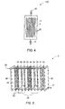
- a supercapacitor desalination device 100 is illustrated in Fig. 4 .
- the supercapacitor desalination device 100 includes the supercapacitor desalination device stack 2 housed in a vessel 1.
- the vessel 1 includes an inlet 10 from where the feed liquid 30 enters the vessel 1, and an outlet 11 from where the dilute liquid 33 exits the vessel 1 after being at least partially de-ionized by the supercapacitor desalination device stack 2.
- the feed liquid 30 may be guided inside the vessel 1 by using external forces. Pumping may create suitable external forces.
- the supercapacitor desalination device stack 2 employs a number of supercapacitor desalination device cells 20.
- Each supercapacitor desalination device cell 20 includes first and second electrodes, and an insulating spacer 23 between the first and the second electrodes.
- An insulating film 24 may be respectively disposed between every pair of adjacent supercapacitor desalination device cells 20. Every pair of supercapacitor desalination device cells 20 is electrically insulating from each other pair.
- the stack 2 further includes a plurality of support plates 29.
- the support plates provide mechanical stability to the structure.
- the support plates 29, the first and second electrodes, the spacer 23, and the insulating film 24 include holes 25 to direct the flow of the feed liquid 30 and to define a hydraulic flow path between the supercapacitor desalination device cells 20.
- the liquid is directed inside the supercapacitor desalination device cells 20 from the direction indicated by the arrow 26. After entering the supercapacitor desalination device cell, the liquid is directed such that it flows through the surface of the first and second electrodes as indicated by the hydraulic flow path 28. The liquid may traverse through the maximum portion of the surface of the first and second electrodes. Subsequently, the liquid exits the supercapacitor desalination device cell 20 as indicated by the arrow 27.
- the feed liquid may be passed through the stack 2 more than once.
- compositions, structures, systems and methods having elements corresponding to the elements of the invention recited in the claims are examples of compositions, structures, systems and methods having elements corresponding to the elements of the invention recited in the claims.
- This written description may enable those of ordinary skill in the art to make and use embodiments having alternative elements that likewise correspond to the elements of the invention recited in the claims.
- the scope of the invention thus includes compositions, structures, systems and methods that do not differ from the literal language of the claims, and further includes other structures, systems and methods with insubstantial differences from the literal language of the claims. While only certain features and embodiments have been illustrated and described herein, many modifications and changes may occur to one of ordinary skill in the relevant art. The appended claims cover all such modifications and changes.
Landscapes
- Engineering & Computer Science (AREA)
- Power Engineering (AREA)
- Manufacturing & Machinery (AREA)
- Microelectronics & Electronic Packaging (AREA)
- Electric Double-Layer Capacitors Or The Like (AREA)
Applications Claiming Priority (2)
| Application Number | Priority Date | Filing Date | Title |
|---|---|---|---|
| CNA2007101654900A CN101425394A (zh) | 2007-10-30 | 2007-10-30 | 一种电极和设备的制造方法 |
| US11/947,328 US20090110806A1 (en) | 2007-10-30 | 2007-11-29 | Method for producing an electrode and device |
Publications (1)
| Publication Number | Publication Date |
|---|---|
| EP2056310A1 true EP2056310A1 (de) | 2009-05-06 |
Family
ID=40365365
Family Applications (1)
| Application Number | Title | Priority Date | Filing Date |
|---|---|---|---|
| EP08167753A Withdrawn EP2056310A1 (de) | 2007-10-30 | 2008-10-28 | Verfahren zur Herstellung einer Elektrode und Vorrichtung |
Country Status (1)
| Country | Link |
|---|---|
| EP (1) | EP2056310A1 (de) |
Cited By (1)
| Publication number | Priority date | Publication date | Assignee | Title |
|---|---|---|---|---|
| CN103274386A (zh) * | 2013-05-24 | 2013-09-04 | 厦门大学 | 一种可控孔径的多孔电极及其制备方法 |
Citations (6)
| Publication number | Priority date | Publication date | Assignee | Title |
|---|---|---|---|---|
| US3378507A (en) * | 1961-12-20 | 1968-04-16 | Gen Electric | Producing microporous polymers |
| US3911080A (en) * | 1971-09-10 | 1975-10-07 | Wright H Dudley | Air pollution control |
| US3992495A (en) * | 1973-09-07 | 1976-11-16 | Sumitomo Chemical Company, Limited | Method of manufacturing a semipermeable membrane from a water-soluble polymeric resin |
| EP0215565A1 (de) * | 1985-08-12 | 1987-03-25 | Ciba Specialty Chemicals Water Treatments Limited | Dispergiermittel |
| US4868222A (en) * | 1985-06-10 | 1989-09-19 | The Dow Chemical Company | Preparation of asymmetric membranes by the solvent extraction of polymer components from polymer blends |
| US4873037A (en) * | 1988-10-05 | 1989-10-10 | The Dow Chemical Company | Method for preparing an asymmetric semi-permeable membrane |
-
2008
- 2008-10-28 EP EP08167753A patent/EP2056310A1/de not_active Withdrawn
Patent Citations (6)
| Publication number | Priority date | Publication date | Assignee | Title |
|---|---|---|---|---|
| US3378507A (en) * | 1961-12-20 | 1968-04-16 | Gen Electric | Producing microporous polymers |
| US3911080A (en) * | 1971-09-10 | 1975-10-07 | Wright H Dudley | Air pollution control |
| US3992495A (en) * | 1973-09-07 | 1976-11-16 | Sumitomo Chemical Company, Limited | Method of manufacturing a semipermeable membrane from a water-soluble polymeric resin |
| US4868222A (en) * | 1985-06-10 | 1989-09-19 | The Dow Chemical Company | Preparation of asymmetric membranes by the solvent extraction of polymer components from polymer blends |
| EP0215565A1 (de) * | 1985-08-12 | 1987-03-25 | Ciba Specialty Chemicals Water Treatments Limited | Dispergiermittel |
| US4873037A (en) * | 1988-10-05 | 1989-10-10 | The Dow Chemical Company | Method for preparing an asymmetric semi-permeable membrane |
Non-Patent Citations (1)
| Title |
|---|
| KARIDURAGANAVAR M Y ET AL: "Ion-exchange membranes: preparative methods for electrodialysis and fuel cell applications", DESALINATION, ELSEVIER, AMSTERDAM, NL, vol. 197, no. 1-3, 2 October 2006 (2006-10-02), pages 225 - 246, XP025161356, ISSN: 0011-9164, [retrieved on 20061002] * |
Cited By (2)
| Publication number | Priority date | Publication date | Assignee | Title |
|---|---|---|---|---|
| CN103274386A (zh) * | 2013-05-24 | 2013-09-04 | 厦门大学 | 一种可控孔径的多孔电极及其制备方法 |
| CN103274386B (zh) * | 2013-05-24 | 2014-11-05 | 厦门大学 | 一种可控孔径的多孔电极及其制备方法 |
Similar Documents
| Publication | Publication Date | Title |
|---|---|---|
| US20090110806A1 (en) | Method for producing an electrode and device | |
| KR101233295B1 (ko) | 흐름전극장치 | |
| Yang et al. | Flow-electrode capacitive deionization using an aqueous electrolyte with a high salt concentration | |
| Kim et al. | Improvement of desalination efficiency in capacitive deionization using a carbon electrode coated with an ion-exchange polymer | |
| KR101022257B1 (ko) | 이온선택성 축전식 탈염 복합전극 및 모듈의 제조 방법 | |
| CN103563027B (zh) | 用于流过式电容性去电离的极化电极 | |
| US6462935B1 (en) | Replaceable flow-through capacitors for removing charged species from liquids | |
| US6761809B2 (en) | Alternating-polarity operation for complete regeneration of electrochemical deionization system | |
| KR101004707B1 (ko) | 이온제거용 축전식 전극 및 그를 이용한 전해셀 | |
| CN101615512B (zh) | 超级电容装置及其制造方法 | |
| KR101047335B1 (ko) | 전극의 제조 방법 | |
| Liu et al. | Performance loss of activated carbon electrodes in capacitive deionization: mechanisms and material property predictors | |
| WO2013147380A1 (ko) | 특정 이온 선택성 축전식 탈염 복합탄소전극 및 이의 제조방법 | |
| Ma et al. | Enhanced charge efficiency and electrode separation utilizing magnetic carbon in flow electrode capacitive deionization | |
| KR101621033B1 (ko) | 이온교환집전체를 가지는 축전식 흐름전극장치 | |
| KR102657824B1 (ko) | 채널형 흐름 전극 단위체를 구비한 전기화학적 셀 | |
| KR101221562B1 (ko) | 흐름전극장치를 이용한 수처리장치 | |
| KR20110016213A (ko) | 이온교환관능기를 가진 엔지니어링 플라스틱을 이용한 축전식 탈염 전극 및 그의 제조 방법 | |
| KR20220012643A (ko) | 흐름전극기반 축전식 탈염을 위한 슬러리 탄소 전극 제조방법 | |
| KR101210525B1 (ko) | 흐름전극장치를 이용한 에너지 저장 장치 | |
| KR20150008348A (ko) | 하이브리드 해수 담수화 시스템 | |
| KR101750417B1 (ko) | 격자형 흐름전극구조체 | |
| US10522849B2 (en) | Electrochemical cell comprising channel-type flowable electrode units | |
| EP2056310A1 (de) | Verfahren zur Herstellung einer Elektrode und Vorrichtung | |
| DE60121444T2 (de) | Austauschbare Durchflusskondensatoren zum Entfernen geladener Arten von Flüssigkeiten |
Legal Events
| Date | Code | Title | Description |
|---|---|---|---|
| PUAI | Public reference made under article 153(3) epc to a published international application that has entered the european phase |
Free format text: ORIGINAL CODE: 0009012 |
|
| AK | Designated contracting states |
Kind code of ref document: A1 Designated state(s): AT BE BG CH CY CZ DE DK EE ES FI FR GB GR HR HU IE IS IT LI LT LU LV MC MT NL NO PL PT RO SE SI SK TR |
|
| AX | Request for extension of the european patent |
Extension state: AL BA MK RS |
|
| 17P | Request for examination filed |
Effective date: 20091106 |
|
| 17Q | First examination report despatched |
Effective date: 20091211 |
|
| AKX | Designation fees paid |
Designated state(s): AT BE BG CH CY CZ DE DK EE ES FI FR GB GR HR HU IE IS IT LI LT LU LV MC MT NL NO PL PT RO SE SI SK TR |
|
| STAA | Information on the status of an ep patent application or granted ep patent |
Free format text: STATUS: THE APPLICATION IS DEEMED TO BE WITHDRAWN |
|
| 18D | Application deemed to be withdrawn |
Effective date: 20150501 |