EP2056384A1 - Brennstoffzellensystem und Verfahren zum Betreiben dieses Systems - Google Patents
Brennstoffzellensystem und Verfahren zum Betreiben dieses Systems Download PDFInfo
- Publication number
- EP2056384A1 EP2056384A1 EP08163919A EP08163919A EP2056384A1 EP 2056384 A1 EP2056384 A1 EP 2056384A1 EP 08163919 A EP08163919 A EP 08163919A EP 08163919 A EP08163919 A EP 08163919A EP 2056384 A1 EP2056384 A1 EP 2056384A1
- Authority
- EP
- European Patent Office
- Prior art keywords
- fuel
- fuel cell
- reformer
- cell stack
- stack
- Prior art date
- Legal status (The legal status is an assumption and is not a legal conclusion. Google has not performed a legal analysis and makes no representation as to the accuracy of the status listed.)
- Granted
Links
Images

Classifications
-
- H—ELECTRICITY
- H01—ELECTRIC ELEMENTS
- H01M—PROCESSES OR MEANS, e.g. BATTERIES, FOR THE DIRECT CONVERSION OF CHEMICAL ENERGY INTO ELECTRICAL ENERGY
- H01M8/00—Fuel cells; Manufacture thereof
- H01M8/04—Auxiliary arrangements, e.g. for control of pressure or for circulation of fluids
- H01M8/04223—Auxiliary arrangements, e.g. for control of pressure or for circulation of fluids during start-up or shut-down; Depolarisation or activation, e.g. purging; Means for short-circuiting defective fuel cells
- H01M8/04231—Purging of the reactants
-
- H—ELECTRICITY
- H01—ELECTRIC ELEMENTS
- H01M—PROCESSES OR MEANS, e.g. BATTERIES, FOR THE DIRECT CONVERSION OF CHEMICAL ENERGY INTO ELECTRICAL ENERGY
- H01M8/00—Fuel cells; Manufacture thereof
- H01M8/04—Auxiliary arrangements, e.g. for control of pressure or for circulation of fluids
-
- H—ELECTRICITY
- H01—ELECTRIC ELEMENTS
- H01M—PROCESSES OR MEANS, e.g. BATTERIES, FOR THE DIRECT CONVERSION OF CHEMICAL ENERGY INTO ELECTRICAL ENERGY
- H01M8/00—Fuel cells; Manufacture thereof
- H01M8/06—Combination of fuel cells with means for production of reactants or for treatment of residues
-
- H—ELECTRICITY
- H01—ELECTRIC ELEMENTS
- H01M—PROCESSES OR MEANS, e.g. BATTERIES, FOR THE DIRECT CONVERSION OF CHEMICAL ENERGY INTO ELECTRICAL ENERGY
- H01M8/00—Fuel cells; Manufacture thereof
- H01M8/06—Combination of fuel cells with means for production of reactants or for treatment of residues
- H01M8/0662—Treatment of gaseous reactants or gaseous residues, e.g. cleaning
-
- H—ELECTRICITY
- H01—ELECTRIC ELEMENTS
- H01M—PROCESSES OR MEANS, e.g. BATTERIES, FOR THE DIRECT CONVERSION OF CHEMICAL ENERGY INTO ELECTRICAL ENERGY
- H01M8/00—Fuel cells; Manufacture thereof
- H01M8/06—Combination of fuel cells with means for production of reactants or for treatment of residues
- H01M8/0606—Combination of fuel cells with means for production of reactants or for treatment of residues with means for production of gaseous reactants
- H01M8/0612—Combination of fuel cells with means for production of reactants or for treatment of residues with means for production of gaseous reactants from carbon-containing material
-
- Y—GENERAL TAGGING OF NEW TECHNOLOGICAL DEVELOPMENTS; GENERAL TAGGING OF CROSS-SECTIONAL TECHNOLOGIES SPANNING OVER SEVERAL SECTIONS OF THE IPC; TECHNICAL SUBJECTS COVERED BY FORMER USPC CROSS-REFERENCE ART COLLECTIONS [XRACs] AND DIGESTS
- Y02—TECHNOLOGIES OR APPLICATIONS FOR MITIGATION OR ADAPTATION AGAINST CLIMATE CHANGE
- Y02E—REDUCTION OF GREENHOUSE GAS [GHG] EMISSIONS, RELATED TO ENERGY GENERATION, TRANSMISSION OR DISTRIBUTION
- Y02E60/00—Enabling technologies; Technologies with a potential or indirect contribution to GHG emissions mitigation
- Y02E60/30—Hydrogen technology
- Y02E60/50—Fuel cells
Definitions
- the present invention relates to a fuel cell system. More particularly, the present invention relates to a fuel cell system and a method for operating the same on shutdown and startup.
- Fuel cells are used as electricity generating systems for generating electrical energy by an oxidation reaction of a fuel and a reduction reaction of an oxidizing agent. Such fuel cells may be classified into polymer electrolyte membrane fuel cells and direct oxidation membrane fuel cells according to the type of fuel they use.
- Polymer electrolyte membrane fuel cells generally have superior output characteristics, lower operating temperatures, and faster starting and response characteristics as compared to direct oxidation membrane fuel cells.
- Polymer electrolyte membrane fuel cell have been widely used as power sources for vehicles, distributed power sources for houses and public buildings, and compact power sources for electronic devices.
- a fuel cell system employing a polymer electrolyte membrane fuel cell generally includes a fuel cell stack, a reformer, a fuel supplier, and an oxidizing agent supplier.
- the fuel supplier generally includes a fuel tank and a fuel pump, and supplies fuel to the reformer.
- the reformer generates hydrogen gas from the fuel and supplies the hydrogen gas to the stack.
- the stack generates electrical energy by an electrochemical reaction between the hydrogen gas from the reformer and an oxidizing agent.
- hydrogen peroxide H 2 O 2
- MEA membrane-electrode assembly
- the present invention provides a fuel cell system and a method for operating the same having advantages in that the system performance can quickly recover when restarted after the system has been stopped. This can be accomplished by filling the stack with unreformed fuel as the system is shut down.
- the invention provides a fuel cell system including a fuel supplier, a reformer, a fuel cell stack, a first valve, and a controller.
- the reformer reforms a fuel supplied from the fuel supplier into hydrogen gas by a reforming reaction
- the fuel cell stack generates electrical energy by an electrochemical reaction between the hydrogen gas supplied from the reformer and an oxidizing agent.
- the first valve is disposed between the fuel supplier and the reformer and the first valve is adapted for selectively supplying (preferably by causing the valve to be in an open state) or blocking (preferably by causing the valve to be in a closed state) fuel to the reformer.
- the fuel is directly supplied from the first valve to the reformer without passing through other functional elements of the system (preferably stack, pumps, valves).
- the controller is used to open the first valve for a period of time after the reforming reaction of the reformer and/or the electrochemical reaction of the fuel cell stack are stopped.
- the fuel cell system may further include a power dissipation circuit electrically connected to the fuel cell stack to dissipate residual power from the fuel cell stack when the electrochemical reaction of the fuel cell stack is stopped.
- the power dissipation circuit is controlled by an external signal.
- the fuel cell system further comprises a fuel recycle conduit adapted to recycle the portion of the fuel from the fuel cell stack to the reformer when the fuel cell system is restarted.
- the reformer may further include a vaporizer that generates steam and a heater for generating heat energy by the combustion of a portion of the fuel in air.
- the fuel cell system may further include a fuel recycle conduit disposed between the fuel cell stack and the vaporizer to recycle the fuel from the fuel cell stack to the vaporizer when the fuel cell system is restarted.
- the portion of the fuel supplied to the reformer and the fuel cell stack is a first portion of the fuel and the reformer further comprises a heater adapted to generate heat energy by combustion of a second portion of the fuel with air.
- Another embodiment of the present invention provides a method for operating a fuel cell system comprising a fuel supplier for supplying a fuel, a reformer for reforming the fuel into hydrogen gas by a reforming reaction, and a fuel cell stack for generating electrical energy by an electrochemical reaction between the hydrogen gas and an oxidizing agent (or a fuel cell system as described above).
- the method includes stopping the reforming reaction of the reformer and the electrochemical reaction of the fuel cell stack based on a stop signal, supplying a portion of the unreformed fuel to the reformer and the fuel cell stack (as soon as the reformer has been sufficiently cooled to prevent further reaction of the fuel), and dissipating power from the fuel cell stack in order to purge the stack of any unreacted hydrogen.
- the generation of heat energy used for the reforming reaction may be stopped by interrupting the flow of fuel and/or air to the heater of the reformer.
- the portion of the fuel supplied to the reformer and the fuel cell stack is a first portion of the fuel
- the reformer further includes a heater supplied by air and a second portion of the fuel, and the supply of heat to the reformer is stopped by interrupting flow of at least one of the second portion of the fuel supplied to the heater, and the air supplied to the heater.
- the portion of the unreformed fuel may be supplied to the reformer and the stack when the temperature of the reformer is below a predetermined temperature. This prevents the fuel from reacting in the reformer.
- Suitable catalysts for the reformer include ruthenium, alumina, and combinations thereof.
- the unreformed fuel may be supplied to the reformer and the stack when the temperature of the reformer has cooled to below 200° C.
- the controller opens the first valve for a (sufficient) period of time in order to supply a portion (sufficient amount) of the fuel to the reformer and the stack thereby preventing hydrogen peroxide from being generated from hydrogen gas (remaining in the stack) after the system is stopped.
- the time period for opening the first valve is adapted such that a sufficient amount of the unreformed fuel can flow to the stack in order to displace (push away) any potential hydrogen gas (or hydrogen peroxide being generated from the hydrogen gas) from the stack.
- the step of supplying unreformed fuel to the stack thereby pushing away any potential hydrogen gas (or hydrogen peroxide being generated from the hydrogen gas) from the stack is carried out directly after the stop signal or directly (i.e. within 10s or less, more preferably within 1s or less, still more preferably within 0.1s or less) after the reformer has been sufficiently cooled to prevent further reaction of the fuel.
- the fuel comprises a gaseous fuel.
- Suitable fuels include methane, propane, butane, and combinations thereof.
- any residual hydrogen remaining in the fuel cell stack after the unreformed fuel has been supplied to the stack is reacted and the resulting power is dissipated by a power dissipation circuit.
- the power may be dissipated at 0.2 volts. More preferably, the power is dissipated when the temperature of the first portion of the fuel is less than about 80° C.
- the method for operating the fuel cell system may further include discharging the unreformed fuel in the fuel cell upon a restart signal.
- the unreformed fuel is discharged from the fuel cell stack and recycled to the reformer, such as to the vaporizer section of the reformer.
- the invention provides a fuel cell system including a fuel supplier, a fuel cell stack, a first valve, a bypass valve, and a controller.
- the reformer reforms a fuel supplied from the fuel supplier into hydrogen gas by a reforming reaction, and the fuel cell stack generates electrical energy by an electrochemical reaction between the hydrogen gas supplied from the reformer and an oxidizing agent.
- the first valve is disposed between the fuel supplier and the reformer for selectively supplying (preferably by causing the valve to be in an open state) or blocking (preferably by causing the valve to be in a closed state) the supply of fuel to the reformer, while the bypass valve is disposed on a bypass conduit connecting the fuel supplier to the fuel cell stack.
- the bypass valve may be used to selectively supply (preferably by causing the bypass valve to be in an open state) or block (preferably by causing the bypass valve to be in a closed state) flow of fuel to the fuel cell stack.
- the fuel is directly supplied from the bypass valve to the stack without passing through other functional elements of the system (preferably stack, pumps, valves).
- the controller operates the first valve as discussed above, and operates the bypass valve by opening the bypass valve for a period of time after the reforming reaction of the reformer and the electrochemical reaction of the fuel cell stack are stopped.
- the step of supplying unreformed fuel to the stack via the bypass thereby pushing away any potential hydrogen gas (or hydrogen peroxide being generated from the hydrogen gas) from the stack is carried out directly after the stop signal (i.e. within 10s or less, more preferably within 1s or less, still more preferably within 0.1s or less).
- the fuel cell system may further include a power dissipation circuit electrically connected to the fuel cell stack to dissipate residual power from the fuel cell stack when the electrochemical reaction of the fuel cell stack is stopped.
- the power dissipation circuit is controlled by an external signal.
- the fuel cell system further comprises a fuel recycle conduit adapted to recycle the portion of the fuel from the fuel cell stack to the reformer when the fuel cell system is restarted.
- the reformer may further include a vaporizer that generates steam and a heater for generating heat energy by the combustion of a portion of the fuel in air.
- the fuel cell system may further include a fuel recycle conduit disposed between the fuel cell stack and the vaporizer to recycle the fuel from the fuel cell stack to the vaporizer when the fuel cell system is restarted.
- the portion of the fuel supplied to the reformer and the fuel cell stack is a first portion of the fuel and the reformer further comprises a heater adapted to generate heat energy by combustion of a second portion of the fuel with air.
- the invention provides a method for operating a fuel cell system including a fuel supplier for supplying a fuel, a reformer for reforming the fuel into hydrogen gas by a reforming reaction, and a fuel cell stack for generating electrical energy by an electrochemical reaction between the hydrogen gas and an oxidizing agent (or a fuel cell system as decribed above).
- the method includes stopping the reforming reaction of the reformer and the electrochemical reaction of the fuel cell stack based on a stop signal, supplying a portion of the unreformed fuel to the fuel cell stack while preventing the unreformed fuel from flowing into the reformer, and dissipating power from the fuel cell stack.
- a portion of the unreformed fuel fills the stack when the system is stopped and any remaining hydrogen is reacted to produce residual power which is dissipated by the power dissipation circuit.
- the fuel cell system is a polymer electrolyte membrane fuel cell system which has superior output characteristics, lower operating temperatures, and faster starting and response characteristics as compared to direct oxidation membrane fuel cells.
- the fuel cell system is used as power sources for vehicles, distributed power sources for houses and public buildings, and compact power sources for electronic devices.
- the fuel cell system utilizes a polymer electrolyte membrane and includes a fuel cell stack, a reformer, a fuel supplier, and an oxidizing agent supplier.
- the fuel supplier includes a fuel tank and a fuel pump, and supplies fuel to the reformer.
- the reformer generates hydrogen gas from the fuel and supplies the hydrogen gas to the stack.
- the stack generates electrical energy by an electrochemical reaction between the hydrogen gas from the reformer and an oxidizing agent.
- the fuel provided from the fuel supplier is different to hydrogen or hydrogen gas.
- FIG. 1 is a schematic diagram of a fuel cell system according to a first embodiment of the present invention.
- the fuel cell system is designed such that a portion of the unreformed fuel can be provided to a fuel cell stack 10 when the fuel cell system is stopped. Deterioration and dehydration of an electrolyte membrane can be prevented. Accordingly, the fuel cell system can generate electrical energy quickly when the fuel cell system is restarted.
- the fuel cell stack 10 includes a plurality of unit cells arranged in a stacked configuration with end plates on the outermost sides of the stacked unit cells.
- a unit cell is the minimum unit for generating electrical energy.
- Each unit cell includes a membrane-electrode assembly (MEA) for inducing an electrochemical reaction, and plate-shaped separators disposed on both sides of the membrane-electrode assembly.
- the first separator faces an anode electrode on a first side of the membrane-electrode assembly and a first channel is formed at the first side.
- the first separator is referred to as an anode separator.
- the second separator faces a cathode side of a second side of the membrane-electrode assembly and a second channel is formed at the second side.
- the second separator is referred to as a cathode separator.
- Hydrogen gas flows in the first channel of the first separator, and an oxidizing agent such as oxygen or air flows in the second channel of the second separator.
- the unit cell can generate electrical energy by an electrochemical reaction between hydrogen and the oxidizing agent.
- the fuel cell system further includes a fuel supplier 20 that, in this embodiment, includes a fuel tank for storing a fuel and a pump for supplying the fuel.
- the fuel supplier 20 supplies the fuel to a reformer 30 which produces hydrogen to the stack.
- the fuel supplier includes a pressurized fuel tank which can feed fuel directly to the reformer without the need for a pump.
- the fuel supplier may supply a fuel directly to the stack 10 according to another fuel cell scheme.
- the reformer 30 reforms the fuel supplied from the fuel supplier 20 into hydrogen gas and provides the hydrogen gas to the stack 10.
- the reformer may employ one or more of a partial oxidation reaction, an auto-thermal reforming reaction, or a steam reforming reaction.
- the reformer 30 employs a steam reforming reaction.
- the reformer 30 includes a vaporizer 31, a heater 33, and a reforming reactor 34.
- a water pump 32 feeds water to the vaporizer 31 to generate steam used for the reforming reaction.
- Air from an air pump 35, and a portion of the fuel from the fuel supplier 20 are fed to the heater 33 where a combustion reaction between the air and fuel provides the heat energy to the reforming reactor 34 to facilitate the reforming reaction.
- the reforming reactor 34 generates hydrogen gas from the fuel using a steam reforming reaction.
- An oxidizing agent supplier 40 supplies an oxidizing agent to the stack 10.
- the oxidizing agent supplier 40 is an air pump that supplies air from the atmosphere to the stack 10.
- a first valve 51 is disposed between the fuel supplier 20 and the reformer 30.
- the first valve 51 selectively allows or blocks the flow of fuel from the fuel supplier 20 to the reformer 30.
- a stack inlet valve 52 is disposed between the reformer 30 and the stack 10 to selectively allow or block the flow of fuel or hydrogen from the reformer 30 to the stack 10.
- the stack inlet valve 52 is optional, i.e. the invention is not limited thereto.
- a power dissipation circuit 60 is provided in electrical connection with the stack 10. The remaining hydrogen is permitted to continue to react in the fuel cell stack 10 while the power dissipation circuit 60 draws the resulting residual power generated by such a reaction.
- the power dissipation circuit 60 is a resistive circuit that is controlled by an external signal (not shown) that is applied when the electrochemical reaction of the stack 10 is stopped.
- the power dissipation circuit is not so limited, and may comprise any circuit or device for dissipating an electrical power load.
- a fuel recycle conduit 70 connects the stack 10 to the vaporizer 31, so that the portion of the unreformed fuel that has been supplied to the fuel cell stack 10 may be recycled back to the reformer 30 when the fuel cell system is restarted, but the invention is not limited thereto.
- a controller 80 is connected to the first valve 51, and controls the operation of the first valve 51.
- the controller 80 opens the first valve 51 during normal operation of the fuel cell system. After the reforming reaction of the reformer 30 and the electrochemical reaction of the stack 10 have been stopped and the reformer has been sufficiently cooled to prevent further reaction of the fuel, the controller 80 opens the first valve 51 for a period of time to supply a portion of the fuel to the reformer 30 and the stack 10.
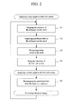
- step S1 is accomplished by stopping the supply of one or both the fuel and air to the heater 33 of the reformer 30.
- the air supplied to the heater 33 may be stopped for a period of time after the supply of the fuel from the fuel supplier 20 to the reformer 30 is stopped by closing the first valve 51. Since this will stop the heater from generating heat energy, the reforming reactor 34 is cooled as time passes.
- a step S2 of supplying a portion of the unreformed fuel to the stack is performed. This may be accomplished by using the controller 80 to open the first valve 51 whereby the unreformed fuel is supplied to and at least partially fills the reformer 30 and the stack 10.
- the first valve 51 in order to prevent a side reaction in the reforming reactor 34, the first valve 51 is only opened after the temperature of the reforming reactor 34 is below a predetermined temperature. If ruthenium, alumina, or a combination is used as a catalyst of the reforming reactor 34, the first valve 51 may be opened when the temperature of the reforming reactor 34 is below 200° C. According to this step, a portion of the unreformed fuel is provided in the first channel, and the oxidizing agent is provided in the second channel of the fuel cell stack 10.
- a step S3 of dissipating power from the stack 10 is performed.
- the amount of power dissipated may be varied according the fuel temperature.
- the power may be dissipated at 0.2 volts when the fuel is 80° C.
- the purpose of this step is to electrochemically react the hydrogen gas remaining in the stack 10 after the portion of unreformed fuel has been provided to the stack. By removing virtually all of the remaining hydrogen, deterioration and dehydration of the electrolyte membrane can be reduced. Accordingly, when the fuel cell system is restarted, the fuel cell system is able to generate electrical energy quickly.
- the fuel is a gaseous fuel such as methane, propane, butane, or combinations thereof.
- some of the fuel in the stack may react and convert into higher order hydrocarbons.
- propane may be converted into hexane
- butane may be converted into octane.
- the portion of unreformed fuel in the stack along with any higher order hydrocarbons such as hexane or octane protects the electrolyte membrane and prevents deterioration and dehydration.
- a step S4 of stopping any remaining operation of the fuel cell system is performed. According to this step, all functions of the fuel cell system can be stopped.
- a step S5 of discharging the unreformed fuel in the stack 10 is performed.
- the portion of unreformed fuel in the stack 10 may be recycled to the reformer 30 or to the other elements of the fuel cell system.
- the fuel discharged from the stack 10 is recycled to the vaporizer 31 through the recycle conduit 70.
- the performance of the fuel cell system is not impaired, and electrical energy can be generated quickly compared to prior art fuel cell systems.
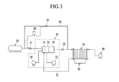
- FIG. 3 is a schematic diagram of a modified fuel cell system of FIG. 1 .
- the fuel cell system further includes a bypass conduit 90 which supplies a portion of the fuel from the fuel supplier 20 to the stack 10, bypassing the reformer 30. A portion of the unreformed fuel may be selectively supplied through the bypass conduit 90 from the fuel supplier 20 or blocked from the fuel supplier by a bypass valve 91.
- the controller 80 controls both the first valve 51 and the bypass valve 91.
- the controller 80 opens the first valve 51 and closes the bypass valve 91 when the fuel cell system operates under normal conditions.
- the controller 80 opens the bypass valve 91 for a (sufficient) period of time to allow a portion of the unreformed fuel to be supplied directly from the fuel supplier 20 to the stack 10, bypassing the reformer 30 thereby preventing hydrogen peroxide from remaining in the stack.
- the controller 80 may simultaneously close the first valve 51 in order to stop the flow of fuel into the reformer 30.
- a single controller 80 is connected to both the first valve 51 and the bypass valve 91.
- the present invention is not limited thereto.
- a first controller corresponding to the first valve 51 and a second controller corresponding to the bypass valve 91 may be used.
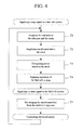
- the method for operating the fuel cell system includes a step T1 of stopping the reforming reaction of the reformer 30 and the electrochemical reaction of the stack 10, for example, by an external stop signal.
- the stop signal may be applied by an operator pushing a shutdown button.
- one or both of the fuel and air to the heater 33 may be stopped by this step so that the heater 33 stops generating heat energy.
- the air supplied to the heater 33 may be stopped for a period of time after the supply of the fuel is blocked.
- the stop signal is transmitted, the unreformed fuel supplied from the fuel supplier 20 to the reformer 30 is stopped by closing the first valve 51.
- the reforming reaction of the reforming reactor 34 is stopped.
- a step T2 of supplying the unreformed fuel to the stack is performed.
- the first valve 51 remains closed and the bypass valve 91 is opened by the controller 80, and thus a portion of the unreformed fuel is supplied to and at least partially fills the stack 10.
- the unreformed fuel is supplied to the stack 10 through the bypass conduit 90, and does not pass through the reformer 30.
- the unreformed fuel is provided to the first channel of the stack 10, and the oxidizing agent is provided to the second channel of the stack 10.
- a step T3 of dissipating power from the stack 10 is performed as described above for the method of FIG. 2 .
- suitable fuels are gaseous fuels such as methane, propane, butane, and combinations thereof.
- a step T4 may be performed in which any remaining operations of the fuel cell system are stopped. However, in other embodiments, some elements of the fuel system may continue to operate.
- a step T5 is performed in which the portion of unreformed fuel previously supplied to the stack 10 is discharged, for example, after a restart signal has been applied.
- the portion of unreformed fuel may be discharged by recycling it to the vaporizer 31. According to this embodiment, when the system is restarted, the performance of the fuel cell system is not impaired, and electrical energy is generated quickly.
Landscapes
- Life Sciences & Earth Sciences (AREA)
- Engineering & Computer Science (AREA)
- Manufacturing & Machinery (AREA)
- Sustainable Development (AREA)
- Sustainable Energy (AREA)
- Chemical & Material Sciences (AREA)
- Chemical Kinetics & Catalysis (AREA)
- Electrochemistry (AREA)
- General Chemical & Material Sciences (AREA)
- Fuel Cell (AREA)
Applications Claiming Priority (1)
| Application Number | Priority Date | Filing Date | Title |
|---|---|---|---|
| KR1020070109498A KR100971745B1 (ko) | 2007-10-30 | 2007-10-30 | 연료 전지 시스템 및 그 운전방법 |
Publications (2)
| Publication Number | Publication Date |
|---|---|
| EP2056384A1 true EP2056384A1 (de) | 2009-05-06 |
| EP2056384B1 EP2056384B1 (de) | 2011-11-16 |
Family
ID=40030388
Family Applications (1)
| Application Number | Title | Priority Date | Filing Date |
|---|---|---|---|
| EP08163919A Not-in-force EP2056384B1 (de) | 2007-10-30 | 2008-09-09 | Brennstoffzellensystem und Verfahren zum Betreiben dieses Systems |
Country Status (5)
| Country | Link |
|---|---|
| US (1) | US8173310B2 (de) |
| EP (1) | EP2056384B1 (de) |
| JP (1) | JP5078657B2 (de) |
| KR (1) | KR100971745B1 (de) |
| CN (1) | CN101425582B (de) |
Cited By (1)
| Publication number | Priority date | Publication date | Assignee | Title |
|---|---|---|---|---|
| EP3147979A4 (de) * | 2014-05-21 | 2017-05-17 | Panasonic Corporation | Festoxidbrennstoffzellensystem und stoppverfahren dafür |
Families Citing this family (9)
| Publication number | Priority date | Publication date | Assignee | Title |
|---|---|---|---|---|
| KR101223708B1 (ko) * | 2010-09-14 | 2013-01-18 | 주식회사 엘지화학 | 트리 블록 공중합체, 및 그로부터 제조되는 전해질 막 |
| CN103022537A (zh) * | 2012-12-31 | 2013-04-03 | 刘军 | 一种具有两种输出形式的低温液相燃料重整器 |
| AU2014346961B2 (en) | 2013-11-06 | 2017-09-28 | Watt Fuel Cell Corp. | Reformer with perovskite as structural component thereof |
| WO2015069836A2 (en) | 2013-11-06 | 2015-05-14 | Watt Fuel Cell Corp. | Gaseous fuel cpox reformers and methods of cpox reforming |
| KR101832864B1 (ko) | 2013-11-06 | 2018-02-27 | 와트 퓨얼 셀 코퍼레이션 | 기체 반응 매질 플로우 관리용 매니폴드를 가지는 화학 반응기 |
| MX352226B (es) | 2013-11-06 | 2017-11-15 | WATT Fuel Cell Corp | Sistemas de reformador cpox de combustible líquido y celdas de combustible, y métodos de producción de electricidad. |
| AU2014346831B2 (en) | 2013-11-06 | 2017-09-07 | Watt Fuel Cell Corp. | Liquid fuel CPOX reformers and methods of CPOX reforming |
| EP3065857B1 (de) | 2013-11-06 | 2022-06-08 | Watt Fuel Cell Corp. | Integrierter cpox-reformer für brenngas und brennstoffzellensysteme sowie verfahren zur erzeugung von strom |
| CN111332124B (zh) * | 2020-04-04 | 2021-09-10 | 东风汽车集团有限公司 | 基于两级保护的燃料电池系统泄放电路 |
Citations (8)
| Publication number | Priority date | Publication date | Assignee | Title |
|---|---|---|---|---|
| US20020064693A1 (en) * | 2000-11-30 | 2002-05-30 | Lacy Robert A. | Residual fuel dissipation for a fuel cell stack |
| US20030010629A1 (en) * | 2001-06-13 | 2003-01-16 | Ballard Power Systems Inc. | Method and device for improved catalytic activity in the purification of fluids |
| JP2003282114A (ja) * | 2002-03-26 | 2003-10-03 | Fuji Electric Co Ltd | 燃料電池発電装置の停止方法 |
| EP1521325A2 (de) * | 2003-10-01 | 2005-04-06 | Matsushita Electric Industrial Co., Ltd. | Brennstoffzellensystem mit Gasdetektor |
| EP1538126A1 (de) * | 2003-12-05 | 2005-06-08 | Matsushita Electric Industrial Co., Ltd. | Wasserstofferzeuger, Verfahren zum Herunterfahren des Wasserstofferzeugers, und Brennstoffzellenanlage |
| EP1659652A1 (de) * | 2003-08-25 | 2006-05-24 | Matsushita Electric Industrial Co., Ltd. | Brennstoffzellensystem und betriebsstopverfahren für ein brennstoffzellensystem |
| JP2007200609A (ja) * | 2006-01-24 | 2007-08-09 | Aisin Seiki Co Ltd | 燃料電池システム |
| EP1892783A1 (de) * | 2005-02-18 | 2008-02-27 | Matsushita Electric Industrial Co., Ltd. | Brennstoffzellensystem und betriebsverfahren dafür |
Family Cites Families (12)
| Publication number | Priority date | Publication date | Assignee | Title |
|---|---|---|---|---|
| JPH02172159A (ja) * | 1988-12-24 | 1990-07-03 | Ishikawajima Harima Heavy Ind Co Ltd | 溶融炭酸塩型燃料電池発電方法及び装置 |
| US4965143A (en) * | 1989-11-09 | 1990-10-23 | Yamaha Hatsudoki Kabushiki Kaisha | Shutdown method for fuel cell system |
| ZA962552B (en) * | 1995-04-05 | 1996-10-07 | Aeci Explosives Ltd | Explosive |
| JP3826833B2 (ja) * | 2002-04-19 | 2006-09-27 | トヨタ自動車株式会社 | 燃料電池システム及びその制御方法 |
| US6835479B2 (en) * | 2002-06-26 | 2004-12-28 | Utc Fuel Cells, Llc | System and method for shutting down a fuel cell power plant |
| JP3978778B2 (ja) | 2002-07-05 | 2007-09-19 | 日産自動車株式会社 | 燃料電池発電システム及びその運転方法 |
| KR20040009647A (ko) * | 2002-07-24 | 2004-01-31 | 엘지전자 주식회사 | 자가 발전 시스템 및 그 제어방법 |
| US8765314B2 (en) | 2003-08-25 | 2014-07-01 | Panasonic Corporation | Fuel cell system and method for stopping operation of fuel cell system |
| US8039154B2 (en) | 2003-08-25 | 2011-10-18 | Panasonic Corporation | Fuel cell system, method of starting fuel cell system |
| JP4593311B2 (ja) * | 2005-02-24 | 2010-12-08 | 三菱電機株式会社 | 燃料電池発電システム及びその停止方法 |
| JP2006344408A (ja) * | 2005-06-07 | 2006-12-21 | Osaka Gas Co Ltd | 燃料電池発電装置、燃料電池発電装置の再起動方法及び燃料電池発電装置の再起動装置 |
| JP2007109529A (ja) * | 2005-10-14 | 2007-04-26 | Mitsubishi Electric Corp | 燃料電池発電システムの制御方法 |
-
2007
- 2007-10-30 KR KR1020070109498A patent/KR100971745B1/ko not_active Expired - Fee Related
-
2008
- 2008-02-18 JP JP2008036214A patent/JP5078657B2/ja not_active Expired - Fee Related
- 2008-05-05 US US12/114,999 patent/US8173310B2/en not_active Expired - Fee Related
- 2008-07-28 CN CN2008101442437A patent/CN101425582B/zh not_active Expired - Fee Related
- 2008-09-09 EP EP08163919A patent/EP2056384B1/de not_active Not-in-force
Patent Citations (8)
| Publication number | Priority date | Publication date | Assignee | Title |
|---|---|---|---|---|
| US20020064693A1 (en) * | 2000-11-30 | 2002-05-30 | Lacy Robert A. | Residual fuel dissipation for a fuel cell stack |
| US20030010629A1 (en) * | 2001-06-13 | 2003-01-16 | Ballard Power Systems Inc. | Method and device for improved catalytic activity in the purification of fluids |
| JP2003282114A (ja) * | 2002-03-26 | 2003-10-03 | Fuji Electric Co Ltd | 燃料電池発電装置の停止方法 |
| EP1659652A1 (de) * | 2003-08-25 | 2006-05-24 | Matsushita Electric Industrial Co., Ltd. | Brennstoffzellensystem und betriebsstopverfahren für ein brennstoffzellensystem |
| EP1521325A2 (de) * | 2003-10-01 | 2005-04-06 | Matsushita Electric Industrial Co., Ltd. | Brennstoffzellensystem mit Gasdetektor |
| EP1538126A1 (de) * | 2003-12-05 | 2005-06-08 | Matsushita Electric Industrial Co., Ltd. | Wasserstofferzeuger, Verfahren zum Herunterfahren des Wasserstofferzeugers, und Brennstoffzellenanlage |
| EP1892783A1 (de) * | 2005-02-18 | 2008-02-27 | Matsushita Electric Industrial Co., Ltd. | Brennstoffzellensystem und betriebsverfahren dafür |
| JP2007200609A (ja) * | 2006-01-24 | 2007-08-09 | Aisin Seiki Co Ltd | 燃料電池システム |
Cited By (2)
| Publication number | Priority date | Publication date | Assignee | Title |
|---|---|---|---|---|
| EP3147979A4 (de) * | 2014-05-21 | 2017-05-17 | Panasonic Corporation | Festoxidbrennstoffzellensystem und stoppverfahren dafür |
| US10096851B2 (en) | 2014-05-21 | 2018-10-09 | Panasonic Corporation | Solid oxide fuel cell system and method of stopping the same |
Also Published As
| Publication number | Publication date |
|---|---|
| US8173310B2 (en) | 2012-05-08 |
| KR20090043764A (ko) | 2009-05-07 |
| KR100971745B1 (ko) | 2010-07-21 |
| CN101425582B (zh) | 2012-05-30 |
| CN101425582A (zh) | 2009-05-06 |
| JP5078657B2 (ja) | 2012-11-21 |
| EP2056384B1 (de) | 2011-11-16 |
| US20090110977A1 (en) | 2009-04-30 |
| JP2009110917A (ja) | 2009-05-21 |
Similar Documents
| Publication | Publication Date | Title |
|---|---|---|
| EP2056384B1 (de) | Brennstoffzellensystem und Verfahren zum Betreiben dieses Systems | |
| EP2351703B1 (de) | Verfahren zum Betreiben einer Wasserstoffproduktionsvorrichtung | |
| JP4670544B2 (ja) | 燃料電池システム | |
| US6887609B2 (en) | Fuel cell system and method for operating the fuel cell system | |
| CN100440598C (zh) | 燃料电池系统、燃料电池系统的起动方法 | |
| JP4463846B2 (ja) | 水素製造発電システム | |
| JP2008251448A (ja) | 燃料電池発電装置におけるスタック電圧制御方法及び装置 | |
| KR100945945B1 (ko) | 연료전지 시스템 및 연료전지 시스템의 퍼지 방법 | |
| US7629066B2 (en) | Fuel cell system configured to detect and control excess load use | |
| US8518589B2 (en) | Fuel cell system and method of operating the same | |
| JP4956226B2 (ja) | 燃料電池発電システムの停止保管方法およびプログラム並びに燃料電池発電システム | |
| US20240352609A1 (en) | Electrolytic synthesis system | |
| US7745060B2 (en) | Fuel cell system and method of operating the fuel cell system | |
| EP2194598A1 (de) | Brennstoffzellensystem und Verfahren zum Betrieb eines Brennstoffzellenstapels | |
| US20050238933A1 (en) | Fuel processing device, fuel cell system having the same, and method of driving thereof | |
| US20200006797A1 (en) | Fuel cell system | |
| KR101060282B1 (ko) | 연료 전지 시스템의 퍼지 방법 | |
| JP4502614B2 (ja) | 燃料電池システム | |
| KR101435384B1 (ko) | 연료전지 운전 시스템 | |
| JP5491284B2 (ja) | 燃料電池システムおよび燃料電池システムの運転方法 | |
| JP4600642B2 (ja) | 燃料電池スタックの異常判定装置 | |
| KR101387758B1 (ko) | 공통 열교환기를 갖는 연료전지 운전 시스템 | |
| JP2006310187A (ja) | 燃料電池システム | |
| KR20140036597A (ko) | 연료전지 운전 시스템 |
Legal Events
| Date | Code | Title | Description |
|---|---|---|---|
| PUAI | Public reference made under article 153(3) epc to a published international application that has entered the european phase |
Free format text: ORIGINAL CODE: 0009012 |
|
| 17P | Request for examination filed |
Effective date: 20080909 |
|
| AK | Designated contracting states |
Kind code of ref document: A1 Designated state(s): AT BE BG CH CY CZ DE DK EE ES FI FR GB GR HR HU IE IS IT LI LT LU LV MC MT NL NO PL PT RO SE SI SK TR |
|
| AX | Request for extension of the european patent |
Extension state: AL BA MK RS |
|
| 17Q | First examination report despatched |
Effective date: 20090923 |
|
| AKX | Designation fees paid |
Designated state(s): DE FR GB HU |
|
| GRAP | Despatch of communication of intention to grant a patent |
Free format text: ORIGINAL CODE: EPIDOSNIGR1 |
|
| GRAS | Grant fee paid |
Free format text: ORIGINAL CODE: EPIDOSNIGR3 |
|
| GRAA | (expected) grant |
Free format text: ORIGINAL CODE: 0009210 |
|
| AK | Designated contracting states |
Kind code of ref document: B1 Designated state(s): DE FR GB HU |
|
| REG | Reference to a national code |
Ref country code: GB Ref legal event code: FG4D |
|
| REG | Reference to a national code |
Ref country code: DE Ref legal event code: R096 Ref document number: 602008011386 Country of ref document: DE Effective date: 20120126 |
|
| PLBE | No opposition filed within time limit |
Free format text: ORIGINAL CODE: 0009261 |
|
| STAA | Information on the status of an ep patent application or granted ep patent |
Free format text: STATUS: NO OPPOSITION FILED WITHIN TIME LIMIT |
|
| 26N | No opposition filed |
Effective date: 20120817 |
|
| REG | Reference to a national code |
Ref country code: DE Ref legal event code: R097 Ref document number: 602008011386 Country of ref document: DE Effective date: 20120817 |
|
| PG25 | Lapsed in a contracting state [announced via postgrant information from national office to epo] |
Ref country code: HU Free format text: LAPSE BECAUSE OF FAILURE TO SUBMIT A TRANSLATION OF THE DESCRIPTION OR TO PAY THE FEE WITHIN THE PRESCRIBED TIME-LIMIT Effective date: 20080909 |
|
| REG | Reference to a national code |
Ref country code: FR Ref legal event code: PLFP Year of fee payment: 8 |
|
| PGFP | Annual fee paid to national office [announced via postgrant information from national office to epo] |
Ref country code: GB Payment date: 20150909 Year of fee payment: 8 Ref country code: DE Payment date: 20150902 Year of fee payment: 8 |
|
| PGFP | Annual fee paid to national office [announced via postgrant information from national office to epo] |
Ref country code: FR Payment date: 20150825 Year of fee payment: 8 |
|
| REG | Reference to a national code |
Ref country code: DE Ref legal event code: R119 Ref document number: 602008011386 Country of ref document: DE |
|
| GBPC | Gb: european patent ceased through non-payment of renewal fee |
Effective date: 20160909 |
|
| REG | Reference to a national code |
Ref country code: FR Ref legal event code: ST Effective date: 20170531 |
|
| PG25 | Lapsed in a contracting state [announced via postgrant information from national office to epo] |
Ref country code: GB Free format text: LAPSE BECAUSE OF NON-PAYMENT OF DUE FEES Effective date: 20160909 Ref country code: DE Free format text: LAPSE BECAUSE OF NON-PAYMENT OF DUE FEES Effective date: 20170401 Ref country code: FR Free format text: LAPSE BECAUSE OF NON-PAYMENT OF DUE FEES Effective date: 20160930 |