EP2056438A2 - Alimentation de puissance à découpage - Google Patents
Alimentation de puissance à découpage Download PDFInfo
- Publication number
- EP2056438A2 EP2056438A2 EP08018850A EP08018850A EP2056438A2 EP 2056438 A2 EP2056438 A2 EP 2056438A2 EP 08018850 A EP08018850 A EP 08018850A EP 08018850 A EP08018850 A EP 08018850A EP 2056438 A2 EP2056438 A2 EP 2056438A2
- Authority
- EP
- European Patent Office
- Prior art keywords
- coil
- coils
- choke
- current
- rectifier circuit
- Prior art date
- Legal status (The legal status is an assumption and is not a legal conclusion. Google has not performed a legal analysis and makes no representation as to the accuracy of the status listed.)
- Withdrawn
Links
- 239000003990 capacitor Substances 0.000 claims abstract description 88
- 230000002441 reversible effect Effects 0.000 claims description 30
- 238000009499 grossing Methods 0.000 claims description 13
- 230000005855 radiation Effects 0.000 abstract description 7
- 239000011162 core material Substances 0.000 description 97
- 101150110971 CIN7 gene Proteins 0.000 description 38
- 101150110298 INV1 gene Proteins 0.000 description 38
- 101100397044 Xenopus laevis invs-a gene Proteins 0.000 description 38
- 230000003071 parasitic effect Effects 0.000 description 33
- 238000006243 chemical reaction Methods 0.000 description 25
- 238000010586 diagram Methods 0.000 description 20
- 230000000694 effects Effects 0.000 description 10
- 230000007423 decrease Effects 0.000 description 9
- 230000004907 flux Effects 0.000 description 8
- 238000004804 winding Methods 0.000 description 8
- 230000009471 action Effects 0.000 description 6
- 230000002457 bidirectional effect Effects 0.000 description 6
- 230000008901 benefit Effects 0.000 description 5
- 230000001629 suppression Effects 0.000 description 5
- 230000002123 temporal effect Effects 0.000 description 3
- 238000007599 discharging Methods 0.000 description 2
- 230000002500 effect on skin Effects 0.000 description 2
- 238000005516 engineering process Methods 0.000 description 2
- 230000005669 field effect Effects 0.000 description 2
- 239000004065 semiconductor Substances 0.000 description 2
- 238000009825 accumulation Methods 0.000 description 1
- 230000002238 attenuated effect Effects 0.000 description 1
- 230000005540 biological transmission Effects 0.000 description 1
- 238000010030 laminating Methods 0.000 description 1
- 238000003475 lamination Methods 0.000 description 1
- 230000004048 modification Effects 0.000 description 1
- 238000012986 modification Methods 0.000 description 1
- 230000010363 phase shift Effects 0.000 description 1
- 239000000758 substrate Substances 0.000 description 1
- 230000001360 synchronised effect Effects 0.000 description 1
Images


Classifications
-
- H—ELECTRICITY
- H02—GENERATION; CONVERSION OR DISTRIBUTION OF ELECTRIC POWER
- H02M—APPARATUS FOR CONVERSION BETWEEN AC AND AC, BETWEEN AC AND DC, OR BETWEEN DC AND DC, AND FOR USE WITH MAINS OR SIMILAR POWER SUPPLY SYSTEMS; CONVERSION OF DC OR AC INPUT POWER INTO SURGE OUTPUT POWER; CONTROL OR REGULATION THEREOF
- H02M7/00—Conversion of AC power input into DC power output; Conversion of DC power input into AC power output
- H02M7/003—Constructional details, e.g. physical layout, assembly, wiring or busbar connections
-
- H—ELECTRICITY
- H01—ELECTRIC ELEMENTS
- H01F—MAGNETS; INDUCTANCES; TRANSFORMERS; SELECTION OF MATERIALS FOR THEIR MAGNETIC PROPERTIES
- H01F27/00—Details of transformers or inductances, in general
- H01F27/28—Coils; Windings; Conductive connections
-
- H—ELECTRICITY
- H02—GENERATION; CONVERSION OR DISTRIBUTION OF ELECTRIC POWER
- H02M—APPARATUS FOR CONVERSION BETWEEN AC AND AC, BETWEEN AC AND DC, OR BETWEEN DC AND DC, AND FOR USE WITH MAINS OR SIMILAR POWER SUPPLY SYSTEMS; CONVERSION OF DC OR AC INPUT POWER INTO SURGE OUTPUT POWER; CONTROL OR REGULATION THEREOF
- H02M1/00—Details of apparatus for conversion
- H02M1/14—Arrangements for reducing ripples from DC input or output
-
- H—ELECTRICITY
- H02—GENERATION; CONVERSION OR DISTRIBUTION OF ELECTRIC POWER
- H02M—APPARATUS FOR CONVERSION BETWEEN AC AND AC, BETWEEN AC AND DC, OR BETWEEN DC AND DC, AND FOR USE WITH MAINS OR SIMILAR POWER SUPPLY SYSTEMS; CONVERSION OF DC OR AC INPUT POWER INTO SURGE OUTPUT POWER; CONTROL OR REGULATION THEREOF
- H02M3/00—Conversion of DC power input into DC power output
- H02M3/02—Conversion of DC power input into DC power output without intermediate conversion into AC
- H02M3/04—Conversion of DC power input into DC power output without intermediate conversion into AC by static converters
- H02M3/10—Conversion of DC power input into DC power output without intermediate conversion into AC by static converters using discharge tubes with control electrode or semiconductor devices with control electrode
- H02M3/145—Conversion of DC power input into DC power output without intermediate conversion into AC by static converters using discharge tubes with control electrode or semiconductor devices with control electrode using devices of a triode or transistor type requiring continuous application of a control signal
- H02M3/155—Conversion of DC power input into DC power output without intermediate conversion into AC by static converters using discharge tubes with control electrode or semiconductor devices with control electrode using devices of a triode or transistor type requiring continuous application of a control signal using semiconductor devices only
- H02M3/156—Conversion of DC power input into DC power output without intermediate conversion into AC by static converters using discharge tubes with control electrode or semiconductor devices with control electrode using devices of a triode or transistor type requiring continuous application of a control signal using semiconductor devices only with automatic control of output voltage or current, e.g. switching regulators
- H02M3/158—Conversion of DC power input into DC power output without intermediate conversion into AC by static converters using discharge tubes with control electrode or semiconductor devices with control electrode using devices of a triode or transistor type requiring continuous application of a control signal using semiconductor devices only with automatic control of output voltage or current, e.g. switching regulators including plural semiconductor devices as final control devices for a single load
- H02M3/1584—Conversion of DC power input into DC power output without intermediate conversion into AC by static converters using discharge tubes with control electrode or semiconductor devices with control electrode using devices of a triode or transistor type requiring continuous application of a control signal using semiconductor devices only with automatic control of output voltage or current, e.g. switching regulators including plural semiconductor devices as final control devices for a single load with a plurality of power processing stages connected in parallel
-
- H—ELECTRICITY
- H02—GENERATION; CONVERSION OR DISTRIBUTION OF ELECTRIC POWER
- H02M—APPARATUS FOR CONVERSION BETWEEN AC AND AC, BETWEEN AC AND DC, OR BETWEEN DC AND DC, AND FOR USE WITH MAINS OR SIMILAR POWER SUPPLY SYSTEMS; CONVERSION OF DC OR AC INPUT POWER INTO SURGE OUTPUT POWER; CONTROL OR REGULATION THEREOF
- H02M3/00—Conversion of DC power input into DC power output
- H02M3/22—Conversion of DC power input into DC power output with intermediate conversion into AC
- H02M3/24—Conversion of DC power input into DC power output with intermediate conversion into AC by static converters
- H02M3/28—Conversion of DC power input into DC power output with intermediate conversion into AC by static converters using discharge tubes with control electrode or semiconductor devices with control electrode to produce the intermediate AC
- H02M3/285—Single converters with a plurality of output stages connected in parallel
-
- H—ELECTRICITY
- H02—GENERATION; CONVERSION OR DISTRIBUTION OF ELECTRIC POWER
- H02M—APPARATUS FOR CONVERSION BETWEEN AC AND AC, BETWEEN AC AND DC, OR BETWEEN DC AND DC, AND FOR USE WITH MAINS OR SIMILAR POWER SUPPLY SYSTEMS; CONVERSION OF DC OR AC INPUT POWER INTO SURGE OUTPUT POWER; CONTROL OR REGULATION THEREOF
- H02M3/00—Conversion of DC power input into DC power output
- H02M3/22—Conversion of DC power input into DC power output with intermediate conversion into AC
- H02M3/24—Conversion of DC power input into DC power output with intermediate conversion into AC by static converters
- H02M3/28—Conversion of DC power input into DC power output with intermediate conversion into AC by static converters using discharge tubes with control electrode or semiconductor devices with control electrode to produce the intermediate AC
- H02M3/325—Conversion of DC power input into DC power output with intermediate conversion into AC by static converters using discharge tubes with control electrode or semiconductor devices with control electrode to produce the intermediate AC using devices of a triode or a transistor type requiring continuous application of a control signal
- H02M3/335—Conversion of DC power input into DC power output with intermediate conversion into AC by static converters using discharge tubes with control electrode or semiconductor devices with control electrode to produce the intermediate AC using devices of a triode or a transistor type requiring continuous application of a control signal using semiconductor devices only
- H02M3/33569—Conversion of DC power input into DC power output with intermediate conversion into AC by static converters using discharge tubes with control electrode or semiconductor devices with control electrode to produce the intermediate AC using devices of a triode or a transistor type requiring continuous application of a control signal using semiconductor devices only having several active switching elements
- H02M3/33576—Conversion of DC power input into DC power output with intermediate conversion into AC by static converters using discharge tubes with control electrode or semiconductor devices with control electrode to produce the intermediate AC using devices of a triode or a transistor type requiring continuous application of a control signal using semiconductor devices only having several active switching elements having at least one active switching element at the secondary side of an isolation transformer
- H02M3/33584—Bidirectional converters
Definitions
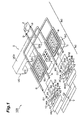
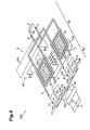
- Fig. 2 shows a cross-sectional constitution of a core material U of the choke coil
- a first choke coil A and a third choke coil D are disposed downstream of the first transformer and a second choke coil C and a fourth choke coil B are disposed downstream of the second transformer.
- the winding of each choke coil is as follows when viewed from above the drawing.
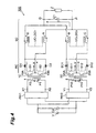
- the secondary coils 20A and 20B are connected to the connection point Y.
- the secondary coils 20A and 20B and the diodes D11 and D12 are connected to the connection point Y of the secondary coils 20A and 20B so that currents S11 and S12 from the cathodes of the diodes D11 and D12 flow alternately in synchronization with the driving by the inverter circuit INV2 and the diodes D11 and D12 constitute a center tap full-wave rectifier circuit in which a current flows to only one diode in a certain period.
- the plurality of rectifier circuits RC are connected to the secondary coils of the first and second transformers.
- the secondary coils 10A, 10B, 20A, and 20B form a center tap connection and the connection points X (Y) of the secondary coils 10A and 10B (20A and 20B) are connected to the choke coils A (C) wound on different cores and the anode sides of the diodes are connected to the choke coil D (B) wound on different cores.
- the currents S1 and S11 (S2, S12) flowing through the secondary coils are smoothed by the inductances of the choke coils A to D and the capacity of the capacitor C1.
- the secondary coils 10A and 10B (20A and 20B) are connected to the connection point X (Y) so that current flows from the diodes D1, D2 (D11, D12).
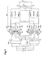
- a serial connection between a coil 1A which forms half of the primary coil 1 and a coil 1B which forms the other half of the primary coil 1 can be considered.
- a serial connection between a coil 2A which forms half of the primary coil 2 and a coil 2B which forms the other half of the primary coil 2 can also be considered.
- the primary coils 1 and 2 whose AC resistances become high alternately during driving by the inverter circuits INV1 and INV2 are connected in series.
- a current S1 or S2 flows to only one of the secondary coils 10A and 10B (20A and 20B) in a certain period.
- the influence of the skin effect and of the proximity effect is reduced and the AC resistance becomes low.
- the AC resistance of the coil 1A (2A) becomes low and the AC resistance of the coil 1B (2B) becomes relatively high.
- the AC resistance of the coil 1B (2B) becomes low and the AC resistance of the coil 1A (2A) becomes relatively high.
- the primary coil 1A When an input voltage at which the current P1 flows to the primary coil 1 is input, the current P1 flows to the primary coils 1A and 1B constituting the primary coil 1.
- the primary coil 1A is disposed close to the secondary coil 10A in which the current S1 flows and is therefore magnetically coupled relatively closely to the secondary coil 10A.
- the primary coil 1A and the secondary coil 10A have a mutually opposite current flow orientation based on transformer principles and therefore the AC resistance in the primary coil 1A becomes low as a result of the proximity effect.
- the primary coil 2B is disposed more remotely than the secondary coil 20A in which the current S11 flows, the primary coil 2B is magnetically coupled relatively loosely to the secondary coil 20A.
- the primary coil 2B is disposed more closely than the secondary coil 20B in which current is not flowing, the AC resistance of the primary coil 2B becomes high as a result of the proximity effect in comparison with the primary coil 2A.
- the primary coils 2A and 2B are connected in series to one another, an equal current flows to the primary coils 2A and 2B.
- the inverter circuits INV1 and INV2 shown in Fig. 1 each comprise the switches Q1, Q2, Q3, and Q4 shown in Figs. 3A and 3B and the timing of the switching, which comprises a few periods T1 to T10, is executed sequentially, thereby driving the inverter circuits. Furthermore, both the inverter circuits INV1 and INV2 are driven in-phase and the timing of the switching of the switches Q1 to Q4 of each of the inverter circuits INV1 and INV2 is the same.
- Periods T1 to T5 represent a half-cycle operation and the periods T6 to T10 represent the remaining half-cycle operation, while the periods T1 to T10 correspond to one cycle of the switching control.
- the other current loop runs from the terminal X2 (Y2), which is one end of the resonance inductor LR, to the high potential line HL1 via the diode DA and returns to the terminal X2 via the switch Q3 and the resonance inductor LR.
- One current loop at this time runs from the output-side terminal X2 (Y2) of the resonance inductor LR, passes via the primary coil 1 (2), the terminal X1 (Y1), and the switch Q1, and returns to the terminal X2 (Y2) sequentially via the high potential line HL1, the capacitor C2 on the input power supply side (See Fig. 1 ), the low potential line LL1, the switch Q4, the node X3 (Y3), and the resonance inductor LR.
- the current flowing through the resonance coil LR the current flowing through the primary coil + the current flowing through the diode DB and, because the current flowing through the resonance coil LR is fixed, the current flowing through the diode DB decreases as a result of the increases in the current flowing through the primary coil and becomes 0A at the end of period T5. The operation of the initial half cycle ends.
- the energy that has accumulated in the resonance inductor LR within the period T6 as mentioned earlier from the point where the potential of the terminal X1 (Y1) is 0V until the point where the switch Q4 is in an OFF state is circulated as current in the circuit connected to the two ends of the resonance inductor LR and the current that does not pass through the primary coil 1 (2) of the transformer also flows in the inverter circuit.
- the absolute value of the current flowing through the primary coil 1 (2) of the transformer decreases.
- the ampere turns in this transformer are equal and the current is divided into a loop current flowing through the rectifier diode D1 (D11) and a loop current flowing through the rectifier diode D2 (D12), which flow to the choke coils A (C).
- the current flowing through the resonance coil LR is fixed.
- the choke coils D, A, B, and C are excited by the voltage across the two ends of the secondary coils 10A and 20A of the transformer, the current flowing through these choke coils increases and the current flowing through the primary coil increases.
- the current flowing through the resonance coil LR the current flowing through the primary coil + the current flowing through the diode DA and, because the current flowing through the resonance coil LR is fixed, the current flowing through the diode DA decreases as a result of the increases in the current flowing through the primary coil.
- the current flowing through the diode DA is 0A, the operation of the latter half cycle ends and returns to the initial state of the period T1.
- the primary coil 1A is magnetically coupled to the secondary coil 10A and has the same polarity.
- the primary coil 1B is magnetically coupled to the secondary coil 20B and has the same polarity. Because the primary coil 1A and primary coil 1B are connected in series, in cases where one AC resistance is relatively greater than the other, the ringing of the current flowing through the primary coils can be suppressed.
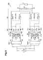
- connection X flows to the terminal P via the choke coil C and the current flowing from the connection point Y likewise flows to the terminal P via the choke coil A.
- each choke coil is charged with the potential difference.
- the potential difference applied to the choke coils is the output voltage, and the serial connection between the choke coils B and A and the serial connection between the choke coils D and C carry the voltage equally.
- a switching power supply with the above structure also functions similarly to the switching power supply shown in Fig. 7 .
- the pairs of secondary coils with a center tap connection are connected to different transformers, the characteristic difference of the transformers can be compensated for and a stable output can be obtained.
- the number of capacitors C1 of the smoothing circuit is one in all in each embodiment, but capacitors may also be provided in a number corresponding with each of the choke coils.
Landscapes
- Engineering & Computer Science (AREA)
- Power Engineering (AREA)
- Dc-Dc Converters (AREA)
Applications Claiming Priority (3)
| Application Number | Priority Date | Filing Date | Title |
|---|---|---|---|
| JP2007280576 | 2007-10-29 | ||
| JP2007340720 | 2007-12-28 | ||
| JP2008202263A JP5176767B2 (ja) | 2007-10-29 | 2008-08-05 | スイッチング電源 |
Publications (2)
| Publication Number | Publication Date |
|---|---|
| EP2056438A2 true EP2056438A2 (fr) | 2009-05-06 |
| EP2056438A3 EP2056438A3 (fr) | 2017-02-22 |
Family
ID=40456260
Family Applications (1)
| Application Number | Title | Priority Date | Filing Date |
|---|---|---|---|
| EP08018850.1A Withdrawn EP2056438A3 (fr) | 2007-10-29 | 2008-10-28 | Alimentation de puissance à découpage |
Country Status (2)
| Country | Link |
|---|---|
| US (1) | US8081492B2 (fr) |
| EP (1) | EP2056438A3 (fr) |
Cited By (2)
| Publication number | Priority date | Publication date | Assignee | Title |
|---|---|---|---|---|
| US9584036B2 (en) | 2011-03-22 | 2017-02-28 | Solarcity Corporation | Solar photovoltaic power conditioning units |
| US11309714B2 (en) | 2016-11-02 | 2022-04-19 | Tesla, Inc. | Micro-batteries for energy generation systems |
Families Citing this family (18)
| Publication number | Priority date | Publication date | Assignee | Title |
|---|---|---|---|---|
| RU2383451C1 (ru) * | 2006-01-17 | 2010-03-10 | Абб Швайц Аг | Топливно-электрическая система привода |
| US8102161B2 (en) * | 2007-09-25 | 2012-01-24 | Tdk Corporation | Stable output in a switching power supply by smoothing the output of the secondary coil |
| US8081492B2 (en) * | 2007-10-29 | 2011-12-20 | Tdk Corporation | Switching power supply with smoothing circuitry for more stable output |
| EP2077609A3 (fr) * | 2007-12-27 | 2017-03-15 | TDK Corporation | Unité de commutation d'alimentation électrique |
| JP5685815B2 (ja) * | 2009-03-16 | 2015-03-18 | Tdk株式会社 | トランスおよびスイッチング電源装置 |
| JP5257204B2 (ja) * | 2009-03-31 | 2013-08-07 | Tdk株式会社 | スイッチング電源装置 |
| US8339808B2 (en) | 2009-06-19 | 2012-12-25 | Tdk Corporation | Switching power supply unit |
| DE102010010235B9 (de) * | 2009-10-19 | 2013-04-18 | Exscitron Gmbh | Vorrichtung zur Ansteuerung einer Mehrzahl von LED-Strängen |
| US8885372B1 (en) * | 2010-09-24 | 2014-11-11 | James Nanut | Low harmonic content AC to DC power conversion |
| DE102010062240A1 (de) * | 2010-12-01 | 2012-06-06 | Robert Bosch Gmbh | Multiphasenwandler |
| EP2795782A4 (fr) * | 2011-12-20 | 2015-09-02 | Exxonmobil Upstream Res Co | Suppression d'harmoniques dans un dispositif de distribution d'énergie électrique |
| CN102570862A (zh) * | 2012-02-15 | 2012-07-11 | 杭州矽力杰半导体技术有限公司 | 一种具有多路输出的电流平衡电路 |
| US8971058B2 (en) * | 2012-08-23 | 2015-03-03 | Allis Electric Co., Ltd. | High-efficiency high step-up ratio direct current converter with interleaved soft-switching mechanism |
| US9647533B2 (en) * | 2013-11-08 | 2017-05-09 | One More Time Llc | PFC circuits with very low THD |
| JP6384096B2 (ja) * | 2014-04-08 | 2018-09-05 | 株式会社デンソー | 電源装置 |
| JP6844253B2 (ja) * | 2016-12-27 | 2021-03-17 | 富士電機株式会社 | 電源装置、一次ブロックおよび二次ブロック |
| US10833591B2 (en) | 2017-07-24 | 2020-11-10 | Abb Power Electronics Inc. | Single-stage DC-DC power converter |
| US11418369B2 (en) * | 2019-08-01 | 2022-08-16 | Analog Devices International Unlimited Company | Minimizing DC bias voltage difference across AC-blocking capacitors in PoDL system |
Citations (2)
| Publication number | Priority date | Publication date | Assignee | Title |
|---|---|---|---|---|
| US6362986B1 (en) | 2001-03-22 | 2002-03-26 | Volterra, Inc. | Voltage converter with coupled inductive windings, and associated methods |
| US20070007908A1 (en) * | 2005-07-06 | 2007-01-11 | Monolithic Power Systems, Inc. | Current balancing technique with magnetic integration for fluorescent lamps |
Family Cites Families (24)
| Publication number | Priority date | Publication date | Assignee | Title |
|---|---|---|---|---|
| US4062057A (en) * | 1977-04-15 | 1977-12-06 | The United States Of America As Represented By The Secretary Of The Navy | Regulated power supply having a series arrangement of inverters |
| EP0186524B1 (fr) * | 1984-12-28 | 1991-03-13 | Kabushiki Kaisha Toshiba | Filtre de ligne |
| JP2629999B2 (ja) | 1990-02-01 | 1997-07-16 | 富士電機株式会社 | Dc/dcコンバータの直列接続回路 |
| US5351175A (en) * | 1993-02-05 | 1994-09-27 | The Lincoln Electric Company | Inverter power supply for welding |
| JPH08181024A (ja) | 1994-12-26 | 1996-07-12 | Tokin Corp | 高調波電流抑制用チョークコイル |
| JP2000260639A (ja) | 1999-03-11 | 2000-09-22 | Murata Mfg Co Ltd | コイル装置およびこれを用いたスイッチング電源装置 |
| DE19961541A1 (de) * | 1999-12-20 | 2001-07-19 | Magnet Motor Gmbh | Hochspannungswandler |
| JP2004022613A (ja) | 2002-06-12 | 2004-01-22 | Kunio Shimazu | 電力増幅トランス回路 |
| US7016203B2 (en) | 2003-01-24 | 2006-03-21 | Virginia Tech Intellectual Properties, Inc. | Self-driven circuit for synchronous rectifier DC/DC converter |
| US6952353B2 (en) | 2003-02-04 | 2005-10-04 | Northeastern University | Integrated magnetic isolated two-inductor boost converter |
| JP2005026846A (ja) | 2003-06-30 | 2005-01-27 | Toyo Commun Equip Co Ltd | 圧電振動子の構造 |
| JP2005086948A (ja) | 2003-09-10 | 2005-03-31 | Tdk Corp | スイッチング電源装置 |
| US7136293B2 (en) | 2004-06-24 | 2006-11-14 | Petkov Roumen D | Full wave series resonant type DC to DC power converter with integrated magnetics |
| JP2006014535A (ja) | 2004-06-28 | 2006-01-12 | Tdk Corp | 並列駆動電源装置 |
| JP3959077B2 (ja) | 2004-06-30 | 2007-08-15 | Tdk株式会社 | 並列駆動電源装置 |
| US6979980B1 (en) * | 2004-08-24 | 2005-12-27 | Advanced Energy Industries, Inc. | Soft switching interleaved power converter |
| US7567163B2 (en) | 2004-08-31 | 2009-07-28 | Pulse Engineering, Inc. | Precision inductive devices and methods |
| US7239530B1 (en) * | 2005-02-17 | 2007-07-03 | Volterra Semiconductor Corporation | Apparatus for isolated switching power supply with coupled output inductors |
| US7176662B2 (en) | 2005-02-23 | 2007-02-13 | Coldwatt, Inc. | Power converter employing a tapped inductor and integrated magnetics and method of operating the same |
| US20070097571A1 (en) | 2005-07-07 | 2007-05-03 | Intel Corporation | Multiphase voltage regulation using paralleled inductive circuits having magnetically coupled inductors |
| JP4482765B2 (ja) * | 2005-09-30 | 2010-06-16 | Tdk株式会社 | スイッチング電源装置 |
| CN101689808B (zh) * | 2007-06-28 | 2012-08-15 | 新电元工业株式会社 | 双向dc/dc转换器 |
| US8102161B2 (en) * | 2007-09-25 | 2012-01-24 | Tdk Corporation | Stable output in a switching power supply by smoothing the output of the secondary coil |
| US8081492B2 (en) * | 2007-10-29 | 2011-12-20 | Tdk Corporation | Switching power supply with smoothing circuitry for more stable output |
-
2008
- 2008-10-27 US US12/258,518 patent/US8081492B2/en not_active Expired - Fee Related
- 2008-10-28 EP EP08018850.1A patent/EP2056438A3/fr not_active Withdrawn
Patent Citations (2)
| Publication number | Priority date | Publication date | Assignee | Title |
|---|---|---|---|---|
| US6362986B1 (en) | 2001-03-22 | 2002-03-26 | Volterra, Inc. | Voltage converter with coupled inductive windings, and associated methods |
| US20070007908A1 (en) * | 2005-07-06 | 2007-01-11 | Monolithic Power Systems, Inc. | Current balancing technique with magnetic integration for fluorescent lamps |
Cited By (4)
| Publication number | Priority date | Publication date | Assignee | Title |
|---|---|---|---|---|
| US9584036B2 (en) | 2011-03-22 | 2017-02-28 | Solarcity Corporation | Solar photovoltaic power conditioning units |
| US10008858B2 (en) | 2011-03-22 | 2018-06-26 | Tesla, Inc. | Solar photovoltaic power conditioning units |
| EP2689525B1 (fr) * | 2011-03-22 | 2020-04-22 | Tesla, Inc. | Unité de l'alimentation contrôlée et efficace du réseau en énergie solaire photovoltaïque avec des convertisseurs continu-continu raccordés en parallèle |
| US11309714B2 (en) | 2016-11-02 | 2022-04-19 | Tesla, Inc. | Micro-batteries for energy generation systems |
Also Published As
| Publication number | Publication date |
|---|---|
| EP2056438A3 (fr) | 2017-02-22 |
| US8081492B2 (en) | 2011-12-20 |
| US20090109709A1 (en) | 2009-04-30 |
Similar Documents
| Publication | Publication Date | Title |
|---|---|---|
| US8081492B2 (en) | Switching power supply with smoothing circuitry for more stable output | |
| US6198260B1 (en) | Zero voltage switching active reset power converters | |
| US8441812B2 (en) | Series resonant converter having a circuit configuration that prevents leading current | |
| US6353547B1 (en) | Three-level soft-switched converters | |
| RU2530010C2 (ru) | Бесконтактное питающее оборудование | |
| US7869237B1 (en) | Phase-shifted bridge with auxiliary circuit to maintain zero-voltage-switching | |
| Sun et al. | A current-fed isolated bidirectional DC–DC converter | |
| US20100328971A1 (en) | Boundary mode coupled inductor boost power converter | |
| US7554820B2 (en) | Series resonant DC-DC converter | |
| US7049712B2 (en) | Primary side ZVS push-pull converter having relatively less losses | |
| WO2002069068A1 (fr) | Convertisseur abaisseur de tension multiphase couple une fixation de niveau et integration magnetique | |
| US7609532B1 (en) | Phase-shifted PWM bridge with switchable inductors to maintain zero-voltage switching at light load | |
| US12362671B2 (en) | Switching power supply circuit | |
| US9509221B2 (en) | Forward boost power converters with tapped transformers and related methods | |
| CN115868105A (zh) | 软开关脉冲宽度调制dc-dc功率转换器 | |
| US5563775A (en) | Full bridge phase displaced resonant transition circuit for obtaining constant resonant transition current from 0° phase angle to 180° phase angle | |
| US8885366B2 (en) | DC-to-DC voltage regulator and its operating method thereof | |
| CN111656661A (zh) | 恒频dc / dc功率转换器 | |
| US6999325B2 (en) | Current/voltage converter arrangement | |
| US7688044B2 (en) | Device for transforming and stabilizing a primary AC voltage for supplying an electric load | |
| JP5176767B2 (ja) | スイッチング電源 | |
| US11356029B2 (en) | Rectifying circuit and switched-mode power supply incorporating rectifying circuit | |
| US11527963B2 (en) | Control unit for improving conversion efficiency | |
| Jang et al. | A new soft-switched contactless battery charger with robust local controllers | |
| JPH114578A (ja) | 電圧変換装置 |
Legal Events
| Date | Code | Title | Description |
|---|---|---|---|
| PUAI | Public reference made under article 153(3) epc to a published international application that has entered the european phase |
Free format text: ORIGINAL CODE: 0009012 |
|
| 17P | Request for examination filed |
Effective date: 20081028 |
|
| AK | Designated contracting states |
Kind code of ref document: A2 Designated state(s): AT BE BG CH CY CZ DE DK EE ES FI FR GB GR HR HU IE IS IT LI LT LU LV MC MT NL NO PL PT RO SE SI SK TR |
|
| AX | Request for extension of the european patent |
Extension state: AL BA MK RS |
|
| RAP1 | Party data changed (applicant data changed or rights of an application transferred) |
Owner name: TDK CORPORATION |
|
| RAP1 | Party data changed (applicant data changed or rights of an application transferred) |
Owner name: TDK CORPORATION |
|
| PUAL | Search report despatched |
Free format text: ORIGINAL CODE: 0009013 |
|
| AK | Designated contracting states |
Kind code of ref document: A3 Designated state(s): AT BE BG CH CY CZ DE DK EE ES FI FR GB GR HR HU IE IS IT LI LT LU LV MC MT NL NO PL PT RO SE SI SK TR |
|
| AX | Request for extension of the european patent |
Extension state: AL BA MK RS |
|
| RIC1 | Information provided on ipc code assigned before grant |
Ipc: H02M 3/158 20060101ALI20170119BHEP Ipc: H02M 3/335 20060101ALI20170119BHEP Ipc: H02M 1/14 20060101ALI20170119BHEP Ipc: H02M 3/28 20060101AFI20170119BHEP Ipc: H01F 27/28 20060101ALI20170119BHEP |
|
| AKX | Designation fees paid |
Designated state(s): AT BE BG CH CY CZ DE DK EE ES FI FR GB GR HR HU IE IS IT LI LT LU LV MC MT NL NO PL PT RO SE SI SK TR |
|
| AXX | Extension fees paid |
Extension state: AL Extension state: RS Extension state: BA Extension state: MK |
|
| 17Q | First examination report despatched |
Effective date: 20181214 |
|
| STAA | Information on the status of an ep patent application or granted ep patent |
Free format text: STATUS: THE APPLICATION HAS BEEN WITHDRAWN |
|
| 18W | Application withdrawn |
Effective date: 20190321 |