EP2056497A2 - Appareil de communication et procédé pour identifier des fautes en communication sans fil - Google Patents
Appareil de communication et procédé pour identifier des fautes en communication sans fil Download PDFInfo
- Publication number
- EP2056497A2 EP2056497A2 EP08253564A EP08253564A EP2056497A2 EP 2056497 A2 EP2056497 A2 EP 2056497A2 EP 08253564 A EP08253564 A EP 08253564A EP 08253564 A EP08253564 A EP 08253564A EP 2056497 A2 EP2056497 A2 EP 2056497A2
- Authority
- EP
- European Patent Office
- Prior art keywords
- radio
- base station
- terminal
- radio base
- threshold
- Prior art date
- Legal status (The legal status is an assumption and is not a legal conclusion. Google has not performed a legal analysis and makes no representation as to the accuracy of the status listed.)
- Withdrawn
Links
Images


Classifications
-
- H—ELECTRICITY
- H04—ELECTRIC COMMUNICATION TECHNIQUE
- H04B—TRANSMISSION
- H04B17/00—Monitoring; Testing
- H04B17/20—Monitoring; Testing of receivers
- H04B17/26—Monitoring; Testing of receivers using historical data, averaging values or statistics
-
- H—ELECTRICITY
- H04—ELECTRIC COMMUNICATION TECHNIQUE
- H04L—TRANSMISSION OF DIGITAL INFORMATION, e.g. TELEGRAPHIC COMMUNICATION
- H04L1/00—Arrangements for detecting or preventing errors in the information received
- H04L1/0001—Systems modifying transmission characteristics according to link quality, e.g. power backoff
- H04L1/0015—Systems modifying transmission characteristics according to link quality, e.g. power backoff characterised by the adaptation strategy
- H04L1/0019—Systems modifying transmission characteristics according to link quality, e.g. power backoff characterised by the adaptation strategy in which mode-switching is based on a statistical approach
-
- H—ELECTRICITY
- H04—ELECTRIC COMMUNICATION TECHNIQUE
- H04L—TRANSMISSION OF DIGITAL INFORMATION, e.g. TELEGRAPHIC COMMUNICATION
- H04L1/00—Arrangements for detecting or preventing errors in the information received
- H04L1/20—Arrangements for detecting or preventing errors in the information received using signal quality detector
-
- H—ELECTRICITY
- H04—ELECTRIC COMMUNICATION TECHNIQUE
- H04L—TRANSMISSION OF DIGITAL INFORMATION, e.g. TELEGRAPHIC COMMUNICATION
- H04L1/00—Arrangements for detecting or preventing errors in the information received
- H04L1/12—Arrangements for detecting or preventing errors in the information received by using return channel
- H04L1/16—Arrangements for detecting or preventing errors in the information received by using return channel in which the return channel carries supervisory signals, e.g. repetition request signals
- H04L1/18—Automatic repetition systems, e.g. Van Duuren systems
Definitions
- the present invention relates to a communication apparatus capable of communicating with a radio terminal and radio base station and a method for identifying faults in a radio link between the radio terminal and radio base station and a computer program storage medium.
- Radio systems compliant with the IEEE802.11 standard have a problem that radio link errors such as radio interference occur and communication performance of radio terminals deteriorate. Therefore, in improving reliability of a radio system, when a radio link error occurs, how to speedily detect the fault which causes it, take remedial actions and shorten a time during which the communication performance deteriorates (MTTR: Mean Time To Repair) is an important issue.
- MTTR Mean Time To Repair
- Examples of the method of detecting a radio link error include a method of taking and observing statistics of the frequency of CRC errors in frames on a radio terminal or base station and thereby detecting radio interference. This is a method using a correlation between the occurrence of interference between frames on a radio link and detection of CRC errors on the radio terminal or base station, and is a method whereby when an increase is observed with respect to the frequencies at which CRC errors is detected, the occurrence of interference is estimated.
- a CRC error is not always a phenomenon caused by only radio interference, but a phenomenon caused when, for example, communication data of a third party who has nothing to do with the other party of communication is received at a low reception level, too. Therefore, a CRC error may occur even when no radio interference occurs or when no communication is being carried out, hence there is a problem that radio interference is detected wrongly.
- radio interference is produced by various faluts such as the collision by a hidden terminal, the multipath fading caused by reflected waves due to walls or the like and non-IEEE802.11 standard interference wave such as a microwave oven and Bluetooth[TM]. That is, even if radio interference can be detected using CRC errors, if the faults cannot be more specifically identified, the administrators cannot take specific remedial actions against the faults such as prevention of a hidden terminal or reflected wave and elimination of interference sources.
- a communication apparatus that identifies a fault of a radio link between a radio terminal and a radio base station, comprising:
- a method for identifying a fault of a radio link between a radio terminal and a radio base station comprising:
- a computer program storage medium storing a computer program for causing a computer to identify a fault of a radio link between a radio terminal and a radio base station, to execute instructions to perform:
- FIG. 1 shows a configuration example of a communication system according to an embodiment of the present invention.
- reference numeral 1 denotes a network
- reference character “M” denotes a communication apparatus (host) connected to the network
- A denotes a radio base station (hereinafter may also be referred to as an "AP") connected to the network 1.
- Reference numeral 2 denotes a radio link and reference character “B” denotes a radio terminal (hereinafter may also be referred to as "STA”) connected to the radio link 2.
- FIG. 1 shows only one radio terminal B connected to the radio base station A, but a plurality of radio terminals may also be connected to the radio base station A.
- FIG. 2 shows a configuration example of the communication apparatus M.
- the communication apparatus M of the present embodiment is provided with a statistical information acquisition unit 11 that acquires statistical information indicating a status of the radio link between the radio terminal and radio base station, a statistical information storage 12 that stores the statistical information acquired by the statistical information acquisition unit 11 together with time information and a fault identification unit 13 that identifies the type of fault of the radio link from the statistical information stored in the statistical information storage 12.
- the statistical information acquisition unit 11, statistical information storage 12 and fault identification unit 13 may be configured as hardware or may also be configured as a software module (computer program) executed on the communication apparatus M or radio base station A or radio terminal B.
- the computer program may be stored in a computer program storage medium like CD-ROM, Memory card and Hard-disk Drive etc, and the computer program may be read out and executed from the computer program storage medium by a computer having a CPU and a memory.
- the RSSI value in (1) is a value indicating signal intensity of a received signal. For example, when an obstacle exists between the STA and AP and mutual radio signals do not arrive, the RSSI value decreases.
- the RSSI value corresponds, for example, to intensity of a received wave.
- the Channel Load in (2) is a ratio of a time judged through carrier sense to be busy for every predetermined time.
- the Channel Load increases when other STAs/APs or the like are communicating. For example, when many STAs are accessing and communicating with a certain AP or when an STA that generates large traffic exists, the increase rate increases.
- NAV Network Allocation Vector
- the frequency of failures to receive an ACK frame in (3) refers to the number of times no ACK frame is received from the other party even when the sender has sent a data frame (DATA frame) and is a statistical value that can be obtained from the sender of the data frame.
- FIG. 5 shows a case where the frequency of failures to receive an ACK frame increases. This frequency increases when a DATA frame sent from the AP to the STA is lost and also increases when ACK is lost even when the DATA frame normally arrives at the STA. However, this frequency does not increase when the transmission of the DATA frame per se cannot be realized in a situation in which the Channel Load is high or the like.
- the reception frequency of duplicate frames in (4) refers to the number of times a data frame (duplicate data frame) identical to an already received data frame has been received, and is a statistical value that can be acquired from the receiver of the data frame.
- FIG. 6 shows a case where the reception frequency of duplicate frames increases.
- a frame judged to be a duplicate frame is a frame which has already been received. That is, when a DATA frame is lost, a retransmission frame is not judged as a duplicate frame, whereas when an ACK frame is lost, a retransmission frame is judged as a duplicate frame. In this way, by observing the reception frequency of duplicate frames, it is possible to judge a state in which the DATA frame arrives normally but the ACK frame is lost.
- the reception frequency of RTS frames in (5) refers to the number of times an RTS frame which includes the destination MAC address neither in the destination address (dst) nor in the source address (src) has been received.
- FIG. 7 shows a case where the reception frequency of RTS frames increases.
- FIG. 3 shows an example of the procedure of the statistical information acquisition unit 11.
- processing of acquiring predetermined first statistical information is executed (step S11).
- the acquisition processing is performed by acquiring statistical information from the radio base station and radio terminal via a network.
- statistical information of the radio base station and radio terminal can be collected via the network using, for example, SNMP (Simple Network Management Protocol) and CAPWAP (Control And Provisioning of Wireless Access Points) which are Internet protocols.
- SNMP Simple Network Management Protocol
- CAPWAP Control And Provisioning of Wireless Access Points
- step S12 the first statistical information acquired by the statistical information acquisition unit 11 is stored in the statistical information storage together with time information.
- steps S11 and S12 a procedure similar to steps S11 and S12 will be repeatedly executed until acquisition processing and storage processing of predetermined Nth statistical information are performed (steps S13 and S14).
- the process is returned to step S11 after a predetermined time of wait (step S15).
- the periodic interval is generally five minutes according to, for example, a statistical acquisition tool on the Internet.
- FIG. 3 shows an example where all statistical information is acquired at the same periodic interval, but a method of setting and acquiring an individual periodic interval for each piece of statistical information may also be adopted.
- a mean value, maximum value, minimum value, standard deviation or the like may be measured on the radio base station and radio terminal and these values may be acquired by the statistical information acquisition unit.
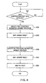
- FIG. 4 shows an example of the procedure of the fault identification unit 13.
- the fault identification unit 13 detects an input to start processing (step S21).
- the start input include periodic input from a periodic timer or the like and a specific instruction from an administrator.
- the start input is periodically given to the fault identification unit 13, it is possible to periodically monitor a situation in which a fault occurs, while as in the latter, when an instruction from the administrator is given as the start input, the administrator can identify the fault on demand and in real time.
- the threshold is predetermined for each piece of statistical information and is set, for example, as follows.
- step S23 A procedure similar to steps S22 and S23 is repeatedly executed until the Nth statistical information is judged and saved (steps S24 and S25).
- the combination of the saved judgment results is compared with a combination predetermined for each fault. As a result of the comparison, if the fault having the same combination exists, it can be identified as the fault (step S26).
- Table 1 in FIG. 24 shows examples of combinations of judgment results predetermined for each fault.
- “Increased” in Table 1 means that a set threshold is exceeded and “Decreased” means that a set threshold is not reached.
- “Increased” and “Decreased” in the statistical information of Table 1 matches the combination of the judgment results, such a case is identified as a case where the corresponding fault has occurred.
- FIG. 8 shows a network configuration in which an STA and an STA' mutually become hidden terminals.
- carrier senses of the STA and STA' do not function and though the STA is sending a data frame to the AP, the STA' sends a data frame to the AP, and as a result, the frames collide with each other, causing interference.
- a feature in this case is that interference occurs only in the DATA frame sent from the STA to the AP and the ACK frame sent from the STA to the AP does not interfere.
- the carrier sense of the STA' functions for the DATA frame which becomes the source of the ACK frame (DATA frame sent from the AP to the STA) and avoids transmission of a frame colliding with the ACK frame. Therefore, it is a state in which only the DATA frame interferes that hidden terminals become a fault and only the frequency of failures to receive an ACK frame on the STA increases.
- the configuration in which the STA suffers damage caused by the hidden terminals has been shown, but there can also be a configuration in FIG. 9 in which the AP suffers damage caused by the hidden terminals likewise. In this case, only the frequency of failures to receive an ACK frame on the AP increases.
- the "exposed terminal” is defined as a terminal that transitions to a waiting state of a NAV (Network Allocation Vector: transmission prohibition period) by receiving an RTS frame sent by the STA connected to a different AP in a wireless LAN system in which RTS (Request To Send)/CTS (Clear To Send) is functioning.
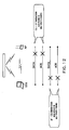
- FIG. 10 shows a network configuration in which an STA becomes an exposed terminal with respect to an STA".
- An AP uses the same channel as that of an AP', the STA is connected to the AP and the STA" is connected to the AP'.
- the STA may receive an RTS frame sent by the STA" to the AP' and in this case, though the utilization rate of the cell to which the STA belongs is low, the STA may transition to a waiting state of NAV and communication performance deteriorates. Therefore, when the exposed terminal becomes a fault, the reception frequency of RTS frames received on the STA (RTS frame in which the MAC address of the AP is included neither in the destination address (dst) nor in the source address (src)) and Channel Load increase. Furthermore, since the STA" becomes a hidden terminal for the AP, a DATA frame sent from the AP to the STA interferes. That is, the frequency of failures to receive an ACK frame on the AP increases.
- the configuration in which the STA becomes the exposed terminal is shown here, but likewise there can also be a configuration in FIG. 11 in which the AP becomes an exposed terminal.
- the reception frequency of RTS frames received on the AP RTS frame in which the MAC address of the STA is included neither in the destination address (dst) nor in the source address (src)
- Channel Load increase, and the frequency of failures to receive an ACK frame on the STA increases.
- the "multipath fading" is defined as a state in which in addition to a direct wave sent from the STA, a reflected wave or the like which is reflected by a wall or the like and arrives is generated and as a result of arriving at the receiving side via a plurality of paths and at different times, these waves interfere with each other.
- FIG. 12 shows a network configuration in which interference due to multipath fading occurs in communication between an STA and an AP.
- non-IEEE802.11 interference is defined as a state in which interference is caused by a radio wave such as a microwave oven and Bluetooth [TM] of the same frequency band, yet of a standard different from IEEE802.11.
- FIG. 13 shows a network configuration in which interference is caused by a non-IEEE802.11 standard radio wave (e.g., microwave oven).
- non-IEEE 802.11 interference occurs, avoidance of collision between both frames of DATA and ACK transmitted/received between the STA and AP frequently occurs and also interferes. Therefore, when non-IEEE802.11 interference becomes a fault, Channel Load on the STA and AP, the frequency of failures to receive an ACK frame and the reception frequency of duplicate frames increase respectively.
- the "congestion” is defined as a state in which the number of STAs belonging to a certain channel increases and avoidance of collision among all APs and STAs belonging to the channel through carrier sense frequently occurs.
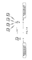
- FIG. 14 shows a network configuration in which congestion has occurred. A congestion state occurs when users locally gather at a meeting or the like and as a result, many STAs access the same AP simultaneously. Therefore, when congestion becomes a fault, Channel Load on the STA and AP increases. However, since DATA and ACK frames are never lost, the number of other parameters never increases.
- the "shadowing" is defined as a state in which an obstacle exists between an STA and an AP and mutual radio signals do not arrive.
- FIG. 15 shows a network configuration in which shadowing occurs.
- shadowing occurs, a direct wave does not reach between the STA and AP due to the obstacle, but a reflected wave and diffracted wave reach and communication is carried out using a received signal with reduced signal intensity.
- signal intensity of received data drastically varies, a PLCP header parity error or CRC error occurs. Therefore, when shadowing becomes a fault, the RSSI value on the STA and AP decreases and both the frequency of failures to receive an ACK frame and the reception frequency of duplicate frames increase.
- FIG. 16 shows a flowchart of a procedure for identifying a hidden terminal (STA).
- the frequency of failures to receive ACK on an STA is judged (step S31).
- ACK threshold a threshold
- AP hidden terminal
- STA exposed terminal
- congestion are excluded from faults (step S32).
- the reception frequency of duplicate frames received on the STA is judged (step S33). If the reception frequency of duplicate frames does not exceed the threshold (duplicate threshold), multipath fading, non-IEEE802.11 interference and shadowing are excluded from faults (step S34).
- any one of Channel Load on the AP (base station side channel load) and the reception frequency of RTS frames received on the AP is judged (step S35).
- Channel Load or the reception frequency of RTS frames does not exceed a threshold (channel threshold or RTS threshold)
- AP exposed terminals
- STA hidden terminals
- the identification accuracy can be improved by adding and executing judgment of other than the statistical information shown here.
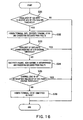
- FIG. 17 shows a flowchart for a procedure for identifying hidden terminals (AP).
- the frequency of failures to receive ACK on an AP is judged (step S41). If the frequency of failures to receive ACK exceeds a threshold (ACK threshold), hidden terminal (STA), exposed terminal (AP) and congestion are excluded from faults (step S42).
- the reception frequency of duplicate frames received on the AP is judged (step S43). If the reception frequency of duplicate frames does not exceed a threshold (duplicate threshold), multipath fading, non-IEEE802.11 interference and shadowing are excluded from the faults (step S44).
- any one of Channel Load on the STA (terminal side channel load) or the reception frequency of RTS frames received on the STA is judged (step S45). If Channel Load or the reception frequency of RTS frames does not exceed a threshold (channel threshold or RTS threshold), there is no possibility that exposed terminals (STA) may be the faults, and hidden terminals (AP) are confirmed to be the fault and can be identified as such (step S46).
- a threshold channel threshold or RTS threshold
- AP hidden terminals
- Channel Load or the reception frequency of RTS frames exceeds a threshold (channel threshold or RTS threshold)
- AP hidden terminals
- STA exposed terminals
- the identification accuracy can be improved by adding and executing judgment of other than the statistical information shown here.
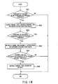
- FIG. 19 shows a flowchart of a procedure for identifying an exposed terminal (AP).
- the frequency of failures to receive ACK on an STA is judged (step S61). If the frequency of failures to receive ACK exceeds a threshold (ACK threshold), hidden terminal (AP), exposed terminal (STA) and congestion are excluded from faults (step S62).
- the reception frequency of duplicate frames received on the STA is judged (step S63). If the reception frequency of duplicate frames does not exceed a threshold (duplicate threshold), multipath fading, non-IEEE 802.11 interference and shadowing are excluded from the faults (step S64).
- any one of Channel Load on the AP and the reception frequency of RTS frames is judged (step S65).
- Channel Load or the reception frequency of RTS frames exceeds a threshold (channel threshold or RTS threshold)
- STA hidden terminals
- AP exposed terminals
- the identification accuracy can be improved by adding and executing judgment of other than the statistical information shown here.
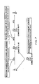
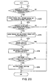
- FIG. 20 shows a flowchart of a procedure for identifying multipath fading.
- the frequency of failures to receive ACK on an AP is judged (step S71). If the frequency of failures to receive ACK exceeds a threshold (ACK threshold), hidden terminal (STA), exposed terminal (AP) and congestion are excluded from faults (step S72).
- the reception frequency of duplicate frames received on the AP is judged (step S73). If the reception frequency of duplicate frames exceeds a threshold (duplicate threshold), hidden terminal (AP) and exposed terminal (STA) are excluded from the faults (step S74).
- Channel Load on the AP is judged (step S75).
- Channel Load does not exceed a threshold (channel threshold)
- non-IEEE802.11 interference is excluded from the faults (step S76).
- an RSSI value on the AP is judged (step S77). If the RSSI value is equal to or higher than a threshold (received intensity threshold), there is no possibility that shadowing may be the faults, and multipath fading is confirmed to be the fault and can be identified as such (step S78).
- the identification accuracy can be improved by adding and executing judgment of other than the statistical information shown here.
- step S71 the frequency of failures to receive ACK on an AP is judged, and in step 573, the reception frequency of duplicate frames received on the AP is judged, but in step S71, the frequency of failures to receive ACK on an STA may be judged, and in step S73, the reception frequency of duplicate frames on the STA may be judged Instead.
- ACK threshold a threshold
- step S72 hidden terminal (AP), exposed terminal (STA) and congestion are excluded from the faults.
- step S74 hidden terminal (STA) and exposed terminal (AP) are excluded from the faults.
- step S75 Channel Load on the AP is judged, but Channel Load on the STA may also be judged instead.
- Channel threshold a threshold
- step S77 above the RSSI value on the AP is judged, but the RSSI value on the STA may also be judged.
- a threshold received intensity threshold
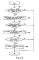
- FIG. 21 shows a flowchart showing a procedure for identifying non-IEEE802.11 interference.
- the frequency of failures to receive ACK on an AP is judged (step S81). If the frequency of failures to receive ACK exceeds a threshold (ACK threshold), hidden terminal (STA), exposed terminal (AP) and congestion are excluded from faults (step S82).
- the reception frequency of duplicate frames received on the AP is judged (step S83). If the reception frequency of duplicate frames exceeds a threshold (duplicate), hidden terminal (AP) and exposed terminal (STA) are excluded from the faults (step S84).
- Channel Load on the AP is judged (step S85).
- Channel Load exceeds a threshold (channel threshold)
- channel threshold threshold
- non-IEEE802.11 interference is confirmed to be the fault and can be identified as such (step S86).
- the identification accuracy can be improved by adding and executing judgment of other than the statistical information shown here.
- the frequency of failures to receive ACK on an AP is judged in step S81 above and the reception frequency of duplicate frames received on the AP is judged in step S83, but instead of this, the frequency of failures to receive ACK on an STA may be judged in step S81 and the reception frequency of duplicate frames received on the STA may be judged in step S83.
- ACK threshold a threshold
- AP hidden terminal
- STA exposed terminal
- congestion are excluded from faults in step S82.
- the reception frequency of duplicate frames received on the STA exceeds a threshold (duplicate threshold)
- hidden terminal (STA) and exposed terminal (AP) are excluded from the faults in step S74.
- Channel Load on the AP is judged, but Channel Load on the STA may also be judged instead.
- Channel threshold a threshold
- the possibility of multipath fading and shadowing is excluded and non-IEEE802.11 interference is identified as the fault.
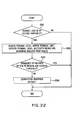
- FIG. 22 shows a flowchart of a procedure for identifying congestion.
- Channel Load on an AP is judged (step S91).
- a threshold channel threshold
- STA hidden terminal
- AP hidden terminal
- STA exposed terminal
- multipath fading and shadowing are excluded from faults (step S92).
- the frequency of failures to receive ACK on an STA is judged (step 593). If the frequency of failures to receive ACK on the STA does not exceed a threshold (ACK threshold), there is no possibility that exposed terminal (AP) and non-IEEE802.11 interference may be the faults, and congestion is confirmed to be the fault and can be identified as such (step S94).
- the identification accuracy can be improved by adding and executing judgment of other than the statistical information shown here.
- Channel Load on the AP is judged in step S91 above and the frequency of failures to receive ACK on an STA is judged in step S93, but instead of this, Channel Load on the STA may be judged in step S91 and the frequency of failures to receive ACK on the AP may be judged in step S93.
- Channel threshold hidden terminal
- AP hidden terminal
- AP exposed terminal
- multipath fading and shadowing are excluded from the faults.
- ACK threshold the possibility of exposed terminal (AP) and non-IEEE802.11 interference is excluded and congestion is identified as the fault.
- FIG. 23 shows a flowchart of a procedure for identifying shadowing.
- an RSSI value on an AP is judged (step S101). If the RSSI value falls short of a threshold (received intensity threshold), there is no possibility of all the other faults, and shadowing is confirmed to be the fault and can be identified as such (step S102). However, since the RSSI value is a value that varies a great deal even in a normal state, the RSSI value may be wrongly detected. Therefore, the identification accuracy can be improved by adding and executing judgments of other than the RSSI value.
- the RSSI value on the AP is judged, but the RSSI value on the STA may be judged instead. By so doing, when the RSSI value on the STA falls short of the threshold (received intensity threshold), the possibility of all the other faults is excluded and shadowing is identified as the fault.
- thresholds receiveived intensity threshold, channel threshold, ACK threshold, duplicate threshold, RTS threshold
- values that vary from one fault to another can be set.
- different values can also be set as these thresholds between the radio terminal and radio base station.
- these thresholds may be dynamically updated according to a variation in an environment of the wireless LAN system and changes of an application used by the radio terminal.
- the fault when a fault can be identified, the fault may also be reported immediately to the administrator by mail or the like so as to prompt the administrator to quickly take remedial actions. Furthermore, in the case of a fault such as congestion for which remedial actions can be taken dynamically under the control of the radio base station, it is also possible to ask the apparatus having the corresponding function for the remedial actions and automate a series of processes from the identification of the fault to the remedial actions.
Landscapes
- Engineering & Computer Science (AREA)
- Computer Networks & Wireless Communication (AREA)
- Signal Processing (AREA)
- Physics & Mathematics (AREA)
- Quality & Reliability (AREA)
- Probability & Statistics with Applications (AREA)
- Electromagnetism (AREA)
- Mobile Radio Communication Systems (AREA)
- Small-Scale Networks (AREA)
Applications Claiming Priority (1)
| Application Number | Priority Date | Filing Date | Title |
|---|---|---|---|
| JP2007286076A JP5142669B2 (ja) | 2007-11-02 | 2007-11-02 | 通信装置、ならびに障害原因を特定するための方法及びプログラム |
Publications (2)
| Publication Number | Publication Date |
|---|---|
| EP2056497A2 true EP2056497A2 (fr) | 2009-05-06 |
| EP2056497A3 EP2056497A3 (fr) | 2014-02-19 |
Family
ID=40293829
Family Applications (1)
| Application Number | Title | Priority Date | Filing Date |
|---|---|---|---|
| EP08253564.2A Withdrawn EP2056497A3 (fr) | 2007-11-02 | 2008-10-30 | Appareil de communication et procédé pour identifier des fautes en communication sans fil |
Country Status (4)
| Country | Link |
|---|---|
| US (1) | US8843079B2 (fr) |
| EP (1) | EP2056497A3 (fr) |
| JP (1) | JP5142669B2 (fr) |
| CN (1) | CN101426215B (fr) |
Cited By (3)
| Publication number | Priority date | Publication date | Assignee | Title |
|---|---|---|---|---|
| US8824972B2 (en) | 2009-09-14 | 2014-09-02 | Kabushiki Kaisha Toshiba | Radio station |
| CN105634809A (zh) * | 2015-12-30 | 2016-06-01 | 瑞斯康达科技发展股份有限公司 | 一种检测方法及装置 |
| US9967764B2 (en) | 2014-02-05 | 2018-05-08 | Nec Corporation | Monitoring apparatus, wireless communication system, failure-cause distinguishing method, and non-transitory computer readable medium storing program |
Families Citing this family (27)
| Publication number | Priority date | Publication date | Assignee | Title |
|---|---|---|---|---|
| JP2012074765A (ja) * | 2010-09-27 | 2012-04-12 | Toshiba Corp | 無線装置、通信障害対策方法および通信障害対策プログラム |
| JP5575010B2 (ja) * | 2011-02-25 | 2014-08-20 | 三菱電機株式会社 | 無線通信装置 |
| CN102802167B (zh) * | 2011-05-25 | 2017-04-05 | 中兴通讯股份有限公司 | 一种获取终端通信链路质量的方法及系统 |
| CN102547850B (zh) * | 2012-02-22 | 2014-04-09 | 深圳市共进电子股份有限公司 | 一种capwap隧道的实现方法 |
| JP5901371B2 (ja) * | 2012-03-20 | 2016-04-06 | 三菱電機株式会社 | 可動式ホーム柵用通信装置 |
| CN102891745B (zh) * | 2012-10-19 | 2015-08-19 | 华为技术有限公司 | 网络设备及其识别终端异常的方法 |
| JP6136830B2 (ja) * | 2013-10-04 | 2017-05-31 | 富士通株式会社 | 干渉源の位置推定装置,位置推定方法及びプログラム |
| CN103686817A (zh) * | 2013-12-31 | 2014-03-26 | 上海斐讯数据通信技术有限公司 | 无线cpe及其与无线基站ap保持稳定连接的方法 |
| JP6210025B2 (ja) * | 2014-07-02 | 2017-10-11 | Smk株式会社 | 無線通信障害の種別判定装置及び家電制御システム |
| CN106160980B (zh) * | 2015-01-30 | 2020-09-15 | 中兴通讯股份有限公司 | 信道质量指示cqi估计方法及装置 |
| JP2017526275A (ja) * | 2015-03-10 | 2017-09-07 | 株式会社東芝 | 露出ノード問題を軽減するためのワイヤレス通信の方法及び装置 |
| CN106162711B (zh) * | 2015-04-10 | 2019-11-05 | 富士通株式会社 | 识别隐藏终端的方法、装置和系统 |
| CN106162710B (zh) * | 2015-04-10 | 2019-11-05 | 富士通株式会社 | 故障检测装置、方法和系统 |
| CN106470128A (zh) * | 2015-08-18 | 2017-03-01 | 富士通株式会社 | 故障检测装置和系统 |
| CN106572070B (zh) * | 2015-10-12 | 2021-07-20 | 中兴通讯股份有限公司 | 一种全双工通信中隐终端的确定方法、及相应装置和系统 |
| CN106603324A (zh) * | 2015-10-20 | 2017-04-26 | 富士通株式会社 | 训练集的获取装置以及方法 |
| CN105517034B (zh) * | 2016-01-06 | 2018-03-02 | 广东欧珀移动通信有限公司 | 一种无线接入网设备的检测方法,及网络设备 |
| CN107306414A (zh) * | 2016-04-21 | 2017-10-31 | 富士通株式会社 | 故障诊断方法、装置和系统 |
| CN107360048A (zh) * | 2016-05-09 | 2017-11-17 | 富士通株式会社 | 节点性能评估方法、装置和系统 |
| CN107920358B (zh) | 2016-10-11 | 2021-01-26 | 富士通株式会社 | 节点诊断装置以及系统 |
| JP7004377B2 (ja) * | 2017-03-08 | 2022-01-21 | 日本電気株式会社 | 無線通信装置、無線通信方法、中継装置及びプログラム |
| JP6691888B2 (ja) * | 2017-03-30 | 2020-05-13 | 日本電信電話株式会社 | 無線通信システムおよび無線通信制御方法 |
| CN109933478B (zh) * | 2017-12-19 | 2021-02-26 | 华为技术有限公司 | 一种存储系统的故障处理方法和存储系统 |
| US11038606B1 (en) * | 2019-04-19 | 2021-06-15 | The Government of the Unites States of Ameroica as represented by the Secretary of the Air Force | Source discrimination of fluctuating radio signals |
| WO2021152694A1 (fr) * | 2020-01-28 | 2021-08-05 | 日本電信電話株式会社 | Système de communication sans fil, station de surveillance, procédé de détection de défauts et programme de communication sans fil |
| CN114422379B (zh) * | 2022-01-20 | 2023-02-28 | 昕锐至成(江苏)光电科技有限公司 | 一种多平台设备无线组网的分析方法 |
| CN115118575B (zh) * | 2022-06-23 | 2024-05-03 | 奇安信科技集团股份有限公司 | 一种监控方法、装置、电子设备及存储介质 |
Family Cites Families (15)
| Publication number | Priority date | Publication date | Assignee | Title |
|---|---|---|---|---|
| US6304594B1 (en) * | 1998-07-27 | 2001-10-16 | General Dynamics Government Systems Corporation | Interference detection and avoidance technique |
| US6459695B1 (en) * | 1999-02-22 | 2002-10-01 | Lucent Technologies Inc. | System and method for determining radio frequency coverage trouble spots in a wireless communication system |
| JP4654507B2 (ja) * | 2000-11-17 | 2011-03-23 | パナソニック株式会社 | アクセスポイント |
| JP2002223218A (ja) * | 2001-01-29 | 2002-08-09 | Toshiba Corp | 無線lanシステム、ソフトウェア及び記録媒体 |
| US7215681B2 (en) * | 2002-09-11 | 2007-05-08 | Itt Manufacturing Enterprises Inc. | Adaptive channel access for carrier sense multiple access based systems |
| CN1262126C (zh) * | 2003-07-01 | 2006-06-28 | 株式会社日立制作所 | 无线局域网的越区切换方法 |
| EP1719301A1 (fr) * | 2004-02-19 | 2006-11-08 | Rockwell Collins Inc. | Adaptation de liaison pour reseaux ad hoc et mailles mobiles |
| AU2005242234A1 (en) * | 2004-04-30 | 2005-11-24 | Interdigital Technology Corporation | Method and system for controlling transmission power of a downlink signaling channel based on enhanced uplink transmission failure statistics |
| JP2006005775A (ja) * | 2004-06-18 | 2006-01-05 | Hewlett-Packard Development Co Lp | ネットワーク性能劣化原因判定方法及び輻輳制御方法 |
| CN100401826C (zh) * | 2005-03-31 | 2008-07-09 | 华为技术有限公司 | 传输链路的故障检测方法 |
| CN100505908C (zh) * | 2006-01-19 | 2009-06-24 | 华为技术有限公司 | 一种链路稳定性的监控方法 |
| US20090225682A1 (en) * | 2006-04-04 | 2009-09-10 | Alex Peter Grote-Lopez | Optimization Procedure for Wireless Networks Operating in Infrastructure Mode with Standard Protocol IEEE 802.11 |
| CN1921686B (zh) * | 2006-07-31 | 2010-05-12 | 华为技术有限公司 | 一种信道质量指示处理方法和系统 |
| US20080144500A1 (en) * | 2006-12-15 | 2008-06-19 | Motorola, Inc. | Control frame feature on demand in a wireless communication system |
| US20080146172A1 (en) * | 2006-12-15 | 2008-06-19 | Motorola, Inc. | Method and system for detecting periodic intermittent interference |
-
2007
- 2007-11-02 JP JP2007286076A patent/JP5142669B2/ja active Active
-
2008
- 2008-10-30 EP EP08253564.2A patent/EP2056497A3/fr not_active Withdrawn
- 2008-10-31 US US12/262,718 patent/US8843079B2/en active Active
- 2008-10-31 CN CN200810173941XA patent/CN101426215B/zh not_active Expired - Fee Related
Non-Patent Citations (1)
| Title |
|---|
| SUNGGEUN JIN ET AL.: "A Novel Idle Mode Operation in IEEE 802.11 WLANs", IEEE, vol. 802, January 2006 (2006-01-01) |
Cited By (4)
| Publication number | Priority date | Publication date | Assignee | Title |
|---|---|---|---|---|
| US8824972B2 (en) | 2009-09-14 | 2014-09-02 | Kabushiki Kaisha Toshiba | Radio station |
| US9967764B2 (en) | 2014-02-05 | 2018-05-08 | Nec Corporation | Monitoring apparatus, wireless communication system, failure-cause distinguishing method, and non-transitory computer readable medium storing program |
| CN105634809A (zh) * | 2015-12-30 | 2016-06-01 | 瑞斯康达科技发展股份有限公司 | 一种检测方法及装置 |
| CN105634809B (zh) * | 2015-12-30 | 2019-02-15 | 瑞斯康达科技发展股份有限公司 | 一种检测方法及装置 |
Also Published As
| Publication number | Publication date |
|---|---|
| CN101426215B (zh) | 2011-09-07 |
| US20090149133A1 (en) | 2009-06-11 |
| CN101426215A (zh) | 2009-05-06 |
| US8843079B2 (en) | 2014-09-23 |
| JP2009117954A (ja) | 2009-05-28 |
| JP5142669B2 (ja) | 2013-02-13 |
| EP2056497A3 (fr) | 2014-02-19 |
Similar Documents
| Publication | Publication Date | Title |
|---|---|---|
| US8843079B2 (en) | Communication apparatus and program for identifying faults and computer program storage medium | |
| JP5148756B2 (ja) | 無線局 | |
| US8085683B2 (en) | Method and apparatus for estimating link quality | |
| CN101084666B (zh) | 在wlan中使用智能天线来运行的接入点及其相关方法 | |
| JP4486147B2 (ja) | ワイヤレスローカルエリアネットワークでの伝送スループットの測定 | |
| CN101578894B (zh) | 用于在无线站中测量干扰的方法和设备 | |
| US8139506B2 (en) | Wireless communication apparatus for data communication through two or more channels | |
| US20170310572A1 (en) | Trouble diagnosis method and apparatus and system | |
| US20120075987A1 (en) | Radio apparatus, method for communication disturbance remedial action and program for communication disturbance remedial action | |
| KR101627885B1 (ko) | 랜덤 액세스 네트워크에서의 통신 링크(들)의 채널 손실률 및 충돌 손실률의 계산을 위한 장치 및 방법 | |
| WO2008012954A1 (fr) | Appareil de communication sans fil, système lan sans fil, procédé de détection d'interférence, et procédé d'évitement d'interférence | |
| CN107360048A (zh) | 节点性能评估方法、装置和系统 | |
| JP2010124056A (ja) | 無線局、通信制御方法及び通信プログラム | |
| Giustiniano et al. | Measuring transmission opportunities in 802.11 links | |
| KR100713378B1 (ko) | 무선 통신 네트워크에서 숨은 스테이션 검출 방법 | |
| JP2006352660A (ja) | 無線lanシステム、その通信状態検出方法及びその通信状態検出プログラム | |
| JP7036019B2 (ja) | 通信装置、通信方法、無線通信システム及びプログラム | |
| WO2007007760A1 (fr) | Appareil terminal de communication et procede de transmission | |
| KR101674968B1 (ko) | 화재 현장에서 충돌 회피를 위한 무선 통신 시스템 및 그것을 이용한 충돌 회피 방법 | |
| CN116600351B (zh) | 数据传输方法、装置及电子设备 | |
| TWI865189B (zh) | 無線收發設備及其無線傳輸處理方法與無線通訊系統 | |
| CN119854817A (zh) | 监测无线网络环境的方法及其电子设备 | |
| Baba et al. | Wireless LAN rate control with frame collision classification | |
| Han et al. | On backoff in fading wireless channels | |
| Abusubaih et al. | Packet loss discrimination in multi-cell 802.11 wireless LANs |
Legal Events
| Date | Code | Title | Description |
|---|---|---|---|
| PUAI | Public reference made under article 153(3) epc to a published international application that has entered the european phase |
Free format text: ORIGINAL CODE: 0009012 |
|
| 17P | Request for examination filed |
Effective date: 20081105 |
|
| AK | Designated contracting states |
Kind code of ref document: A2 Designated state(s): AT BE BG CH CY CZ DE DK EE ES FI FR GB GR HR HU IE IS IT LI LT LU LV MC MT NL NO PL PT RO SE SI SK TR |
|
| AX | Request for extension of the european patent |
Extension state: AL BA MK RS |
|
| RIC1 | Information provided on ipc code assigned before grant |
Ipc: H04B 17/00 20060101AFI20131204BHEP Ipc: H04L 1/12 20060101ALN20131204BHEP |
|
| PUAL | Search report despatched |
Free format text: ORIGINAL CODE: 0009013 |
|
| AK | Designated contracting states |
Kind code of ref document: A3 Designated state(s): AT BE BG CH CY CZ DE DK EE ES FI FR GB GR HR HU IE IS IT LI LT LU LV MC MT NL NO PL PT RO SE SI SK TR |
|
| AX | Request for extension of the european patent |
Extension state: AL BA MK RS |
|
| AKX | Designation fees paid |
Designated state(s): DE FR GB |
|
| STAA | Information on the status of an ep patent application or granted ep patent |
Free format text: STATUS: THE APPLICATION HAS BEEN WITHDRAWN |
|
| 18W | Application withdrawn |
Effective date: 20160129 |