EP2056533A1 - Effiziente dreifach modulare Redundanz an einem geflochtenen Ring - Google Patents
Effiziente dreifach modulare Redundanz an einem geflochtenen Ring Download PDFInfo
- Publication number
- EP2056533A1 EP2056533A1 EP08168400A EP08168400A EP2056533A1 EP 2056533 A1 EP2056533 A1 EP 2056533A1 EP 08168400 A EP08168400 A EP 08168400A EP 08168400 A EP08168400 A EP 08168400A EP 2056533 A1 EP2056533 A1 EP 2056533A1
- Authority
- EP
- European Patent Office
- Prior art keywords
- node
- nodes
- data
- integrity
- guardian
- Prior art date
- Legal status (The legal status is an assumption and is not a legal conclusion. Google has not performed a legal analysis and makes no representation as to the accuracy of the status listed.)
- Ceased
Links
Images


Classifications
-
- H—ELECTRICITY
- H04—ELECTRIC COMMUNICATION TECHNIQUE
- H04L—TRANSMISSION OF DIGITAL INFORMATION, e.g. TELEGRAPHIC COMMUNICATION
- H04L12/00—Data switching networks
- H04L12/28—Data switching networks characterised by path configuration, e.g. LAN [Local Area Networks] or WAN [Wide Area Networks]
- H04L12/42—Loop networks
- H04L12/437—Ring fault isolation or reconfiguration
-
- G—PHYSICS
- G06—COMPUTING OR CALCULATING; COUNTING
- G06F—ELECTRIC DIGITAL DATA PROCESSING
- G06F11/00—Error detection; Error correction; Monitoring
- G06F11/07—Responding to the occurrence of a fault, e.g. fault tolerance
- G06F11/16—Error detection or correction of the data by redundancy in hardware
- G06F11/18—Error detection or correction of the data by redundancy in hardware using passive fault-masking of the redundant circuits
- G06F11/182—Error detection or correction of the data by redundancy in hardware using passive fault-masking of the redundant circuits based on mutual exchange of the output between redundant processing components
-
- G—PHYSICS
- G06—COMPUTING OR CALCULATING; COUNTING
- G06F—ELECTRIC DIGITAL DATA PROCESSING
- G06F11/00—Error detection; Error correction; Monitoring
- G06F11/07—Responding to the occurrence of a fault, e.g. fault tolerance
- G06F11/16—Error detection or correction of the data by redundancy in hardware
- G06F11/20—Error detection or correction of the data by redundancy in hardware using active fault-masking, e.g. by switching out faulty elements or by switching in spare elements
- G06F11/2002—Error detection or correction of the data by redundancy in hardware using active fault-masking, e.g. by switching out faulty elements or by switching in spare elements where interconnections or communication control functionality are redundant
- G06F11/2007—Error detection or correction of the data by redundancy in hardware using active fault-masking, e.g. by switching out faulty elements or by switching in spare elements where interconnections or communication control functionality are redundant using redundant communication media
-
- G—PHYSICS
- G06—COMPUTING OR CALCULATING; COUNTING
- G06F—ELECTRIC DIGITAL DATA PROCESSING
- G06F11/00—Error detection; Error correction; Monitoring
- G06F11/07—Responding to the occurrence of a fault, e.g. fault tolerance
- G06F11/16—Error detection or correction of the data by redundancy in hardware
- G06F11/20—Error detection or correction of the data by redundancy in hardware using active fault-masking, e.g. by switching out faulty elements or by switching in spare elements
- G06F11/202—Error detection or correction of the data by redundancy in hardware using active fault-masking, e.g. by switching out faulty elements or by switching in spare elements where processing functionality is redundant
Definitions
- TMR Triple Modular Redundant
- TDMA time division multiple access
- TDMA-based TMR configurations require extensive overhead in the form of interstages and/or software overhead to perform the voting that is done in connection with selecting a TMR output.
- TDMA-based TMR configurations often use multiple TDMA slots/ transmissions to share or observe the output from each member of the TMR set.
- One embodiment comprises a network that includes a plurality of bidirectional links and a plurality of nodes. Each node is communicatively coupled to two neighbor nodes and to two skip nodes using the plurality of bi-directional links. Three neighboring nodes of the plurality of nodes form a triple modular redundant (TMR) set having a first end node, a second end node, and a center node, the first end node configured to transmit output data in a first direction and the second end node configured to transmit output data in a second direction.
- TMR triple modular redundant
- a network comprises a plurality of nodes communicatively coupled to one another over first and second logical communication channels. Each of the plurality of nodes is communicatively coupled to respective first and second neighbor nodes and respective first and second skip nodes.
- the plurality of nodes comprises a redundant set of nodes comprising at least three nodes.
- the redundant set transmits first data: (A) the redundant set transmits the first data on both the first and second logical communication channels; (B) each of the plurality of nodes that is not in the redundant set forwards along the first logical communication channel any data received on the first logical communication channel from a respective first neighbor node and forwards along the second logical communication channel any data received on the second logical communication channel from a respective second neighbor node; and (C) at least one of the plurality of nodes that is not in the redundant set determines the integrity of data received from the redundant set based on at least: (i) a comparison of data received on the first logical communication channel from a respective first neighbor node with data received on the first logical communication channel from a respective first skip node; (ii) a comparison of data received on the second logical communication channel from a respective second neighbor node with data received on the second logical communication channel from a respective second skip node; and (iii) a comparison of data received on the first logical communication channel from one of the respective first
- Figure 1 is a block diagram of one embodiment of a half-duplex network.
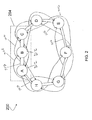
- Figure 2 is a block diagram of one embodiment of a full-duplex network.
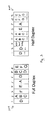
- Figure 3 is a diagram of exemplary time division multiple access schedules.
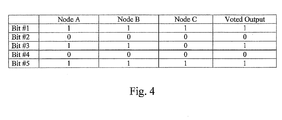
- Figure 4 is a chart of one embodiment of voting comparisons in a triple modular redundant set.
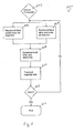
- Figure 5 is a flow chart of one embodiment of a method of voting in an end node.
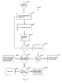
- Figure 6 is a flow chart of one embodiment of a method of processing data in a guardian node.
- Figure 7 is a flow chart of one embodiment of a method of processing data in receiving nodes.
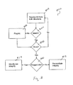
- Figure 8 is a flow chart of one embodiment of a method of reconstituting integrity.
- FIG. 1 is a block diagram of one embodiment of a network 100.
- network 100 employs a half-duplex braided-ring topology.
- the network 100 includes eight nodes 102, which are individually referenced herein as node A through node H. Although eight nodes are shown in Figure 1 , it is to be understood that any number of nodes can be used in other embodiments.
- Each of the nodes 102 is coupled to its two immediate neighbors (also referred to herein as "direct neighbors") via respective direct links 108 and to its neighbors' neighbor (also referred to herein as "skip neighbors" or "skip nodes”) via respective skip links 106.
- direct links 108 and skip links 106 are implemented using respective half-duplex bidirectional links. In other embodiments, direct links 108 and skip links 106 are implemented using respective full-duplex bi-directional links as shown in Fig. 2 .
- nodes 102 are not shown; however, it is understood that the nodes 102 are implemented using suitable hardware and/or software to implement the functionality described here as being performed by the nodes 102.
- Each such node 102 also includes a suitable network or other interface for communicatively coupling that node to the links 108 and 106. Examples of suitable node implementations are described in the '933 Application and the '249 Application, though it is to be understood that the nodes 102 can be implemented other ways.
- the links 106 and 108 are used to form at least two logical communication channels.
- the first logical communication channel comprises a communication path around the ring in a first direction (for example, in a clockwise direction)
- the second logical communication channel comprises a communication path around the ring in a second direction (for example, in a counter-clockwise direction).
- the two logical communication channels are implemented in a half-duplex manner using a single braided ring. In other embodiments, such channels are implemented in other ways.
- the two logical communication channels are implemented using two full-duplex braided rings around the network.
- nodes A, B, and C form a triple modular redundant (TMR) set 104.
- TMR set 104 has two end nodes (nodes A and C in Fig. 1 ) and a center node (node B in Fig. 1 ).
- TMR set 104 provides voted output data. That is, the local data from each of nodes A, B, and C is compared to each other and the output of the TMR set 104 as a whole is selected based on that comparison.
- Each of the end nodes (nodes A and C) provides the voted output data to a respective guardian node (nodes H and D in Fig. 1 ).
- a guardian node is a node that is adjacent to one of the end nodes in the TMR set 104 but that is not a member of the TMR set 104.
- the terms “adjacent” and “neighboring” refer to being communicatively coupled to another node via a direct link 108.
- Each guardian node (H and D) is also coupled to the center node (B) of the TMR set 104 via respective skip links 106.
- Each guardian node compares the voted output data received from the end node to which it is coupled via a direct link 108 with a corresponding output received from the center node to which it is coupled via skip link 106.
- the guardian nodes H and D forward only the voted output data received from end nodes A and C, respectively, and indicate the integrity (high or low) of the forwarded output data based on the comparison with the output received from the center node.
- the voted output data propagates in two directions around the braided ring.
- each guardian node indicates low integrity (for example, due to a mismatch between the voted output data from the end nodes and the output data from the center node)
- each node not in TMR set 104, including guardian nodes H and D is able to reconstitute the integrity of the forwarded voted output data by comparing the forwarded data received in both directions.
- the integrity of the forwarded data is viewed as high even if a mismatch was detected at each of guardian nodes H and D.
- the reconstituted data is trusted as having high integrity because of the voting action in TMR set 104 combined with the integrity comparisons at each node. In this way, faulty data from node B is isolated by the agreement of the voted data from nodes A and C from each direction.
- each node in TMR set 104 receives data, such as sensor data, for performing calculations.
- data such as sensor data
- the data that the nodes in TMR set 104 will transmit must be agreed upon or otherwise selected or obtained such that the outputs are bit-for-bit identical.
- each node in TMR set 104 exchanges its received data with the other members of TMR set 104 to verify that each member received the same data. Each member then performs the same calculation using the received data.
- the calculated result is identical from each member of TMR set 104 unless one of nodes A, B, and C is faulty.
- nodes A, B, and C perform a bounded comparison on the calculated results internally prior to transmitting. For example, if the calculated result in node A is different, but within a set limit, of the calculated result from node C, node A chooses to use the data from node C. The determination of which calculated result to use can be determined a priori.
- TMR set 104 when TMR set 104 is scheduled to transmit, nodes A, B, and C exchange data and vote on an output.
- An exemplary TDMA schedule for a half-duplex network is shown in Fig. 3 .
- a slot is reserved for an internal local comparison of data received at each member of TMR set 104, as shown in Fig. 3 .
- TMR set 104 comprising nodes A, B, and C, transmits in two time slots, one slot for each of two directions.
- node D transmits in two time slots allowing data to propagate completely around the ring in both directions.
- nodes E and A are only assigned one time slot.
- Nodes E and A transmit data in both directions in one time slot and the network uses a fault-tolerant half-duplex propagation method to prevent collision.
- the fault-tolerant half-duplex propagation method is described in more detail in the '305 application.
- more than one TMR set can be used in some embodiments as indicated by time slots for a TMR set comprising nodes E, F, and G.
- node A When TMR set 104 is scheduled to transmit, node A receives data from node B via a corresponding direct link 108 and data from node C via a corresponding skip link 106.
- Node A compares its local data with the data received from nodes B and C.
- node A compares its local data with data from node C, its local data with the data from node B, and the data from node B with the data from node C.
- node A compares the data by performing a bit-by-bit comparison as data is received from nodes C and B. If one of nodes B and C provides a different or faulty bit, node A blocks the different bit and outputs the majority vote (e.g. the bit on which two nodes agree).
- the voted output for each bit is based on the majority value of each bit provided by nodes A, B, and C.
- nodes A and B provide a logical value of "1" for bit #3
- node C provides a logical value of "0" for bit #3.
- the voted output for bit #3 is therefore, a logical "1". In this manner, noise or other interference which causes a faulty bit from one of nodes A, B, and C is masked by the majority vote for that bit.
- the bit-by-bit comparison is performed in the hardware of node A in this embodiment. Additionally, node A sends the voted output data in near real-time. That is, node A sends the voted output on a bit-by-bit basis as the voting above is performed. However, it is to be understood that, in other embodiments, voting can be performed in other manners. For example, in some embodiments, voting is performed in software residing on machine readable media in node A. Also, in other embodiments, node A stores data received from nodes B and C and compares the data once all data has been received.
- the voted output data is sent from node A to guardian node H via a corresponding direct link 108.
- node B sends its local data to node H over its corresponding skip link 106.
- Node H compares the voted output data received from node A with the local data received from node B. If node H determines there is a mismatch, it forwards the output data from node A with an indication of low integrity. If the data from node A is the same as the data from node B, node H forwards the data with an indication of high integrity. For example, an integrity bit can be appended to the forwarded data to indicate low or high integrity. Alternatively, the data can be truncated at the CRC field. In this way, the payload of the frame is passed on and the truncated CRC field indicates the low integrity.
- node H forwards only the data received from node A over direct link 108. In this example, node H does not forward data from node B even if no data is received from node A. However, if TMR set 104 is not scheduled to transmit, node H can forward data from node B. Whether or not node H forwards data from node B is determined by the TDMA schedule.
- Node H forwards the data received from node A to node G via the respective direct link 108 and to node F via the respective skip link 106.
- Node G also receives the voted output from node A via a corresponding skip link 106. Similar to node H, node G compares the data received via skip link 106-N to the forwarded data received via direct link 108 to determine the integrity of the received data. Node G forwards data from either node A or node H with an indication of high or low integrity based on the comparison. Therefore, if node G does not receive data over the skip link 106 or the direct link 108, node G forwards the data available. Similar comparisons are made, at each node, between the data received from the same direction over skip links 106 and direct links 108.
- a similar process occurs for propagating the voted output from TMR 104 in the second direction around the ring in a second time slot.
- node C receives data from nodes A and B and votes the output as described above with regards to node A.
- node B outputs its local data over a skip link 106 to guardian node D.
- guardian node D only forwards data received over a direct link 108 from node C.
- Other processing to propagate the voted output in the second direction is similar to the processing described above with regards to the first direction.
- the voted output data is propagated in two directions.
- Nodes 102 which receive the voted output data in both directions via direct links 108 and skip links 106 also determine the integrity of the forwarded data by comparing the forwarded data received in each direction to each other. For example node F receives the forwarded output data from both nodes G and E. If node F determines that the data is the same, it reconstitutes the integrity of the forwarded data as having high integrity even if each of guardian nodes H and D had indicated that the forwarded voted output data has low integrity. For example, node F can set the integrity bit to indicate high integrity. Alternatively, node F can calculate the CRC and append the recalculated CRC to indicate the high integrity.
- node F receives the voted output in both directions at different times.
- node F receives the voted output data in the first direction during a first time slot and the voted output data in the second direction during a second time slot.
- nodes 102 are configured with de-skew logic which tracks the timing of each bit and enables the bits to be compared to the correct corresponding bit received from the opposite direction.
- the voted output data propagated in the first direction is faulty (such as due to a faulty node A)
- the voted output data propagated around the ring in the second direction is used if it passes integrity tests at guardian node D (which is the case since nodes B and C are non-faulty).
- the voted output data propagated in the second direction is faulty (such as due to a faulty node C)
- the voted output data propagated around the ring in the first direction is used if it passes integrity tests at guardian node H.
- each node 102 not in TMR set 104 reconstitutes the integrity as high integrity if the voted output in both directions matches.
- FIG. 2 is a block diagram of one embodiment of a network 200.
- Network 200 is similar to network 100 except that direct links 208 and skip links 206 are full-duplex bi-directional links.
- the voted output is transmitted from end nodes A and C and propagated around the ring in both directions substantially simultaneously.
- Nodes 202 also use de-skew logic to properly correlate and compare bits of the voted output.
- each node 202 not in TMR set 204 performs integrity comparisons on data from each direction at substantially the same time as it performs integrity reconstitution comparisons on data from opposite directions.
- TMR set 204 only needs one TDMA time slot to complete transmission.
- Processing in nodes of network 200 is similar to the processing in nodes of network 100 and described in more detail below.
- a TDMA schedule of a full-duplex network is shown in Fig. 3 .
- schedule 302 only one TDMA time slot is needed for the TMR set comprising nodes A, B, and C.
- nodes B and C are both member of two different TMR sets.
- the first TMR set comprises nodes A, B, and C; while the second TMR set comprises nodes B, C, and D.
- nodes B and C are configured a priori to be members of the two TMR sets.
- the TMR set comprising nodes A, B, and C is shifted due to a faulty node A. Hence, a faulty node A is replaced by shifting to include node D in the second TMR set.
- TMR sets 104 and 204 do not need additional voting inter-stages to vote on the output of each of the members of the TMR sets as in typical TMR configurations.
- voting is done at the end nodes and integrity comparisons are done at guardian nodes and around the ring as the voted output data is propagated.
- software overhead associated with voting e.g. memory, processing power, etc.
- TDMA time division multiple access
- a typical TMR configuration requires 3 TDMA time slots/transmissions to share/observe the output from each member of the TMR set.
- full-duplex bi-directional links as in network 200, only 1 TDMA time slot/transmission is required.
- half-duplex bi-directional links as in network 100 only 2 TDMA time slots/transmissions are required.
- the data that the nodes in the TMR set 104 transmit (when transmitting as part of the TMR set 104) is agreed upon or otherwise selected or obtained in other ways.
- the nodes 102 of the TMR set 104 are communicatively coupled to one another using the same type of communication links used to communicatively couple the TMR et 104 to the other nodes in the network 100 and the other nodes to one another.
- the nodes 102 of the TMR set 104 are communicatively coupled to one another using links that are different than the links used to communicatively couple the TMR set 104 to the other nodes of the network and the other nodes to one another.
- FIG. 5 is a flow chart of one embodiment of a method 500 of voting an output in an end node (for example, end nodes A and C above).
- a TMR set for example, TMR set 104
- a first end node receives a bit of local data from a second end node via a skip link (for example, skip link 106) at 504.
- the first end node receives a bit of local data from a center node via a direct link (for example, direct link 108) at 506.
- the first end node compares each received bit with a corresponding bit in the local data of the first end node at 508. The comparison determines a majority vote for each bit as described above with reference to Fig. 4 . Once the majority vote is determined, the first end node transmits the majority vote on its output direct link and output skip link in a first direction at 510. At 512, it is determined if all bits of the local data have been received and processed. If there are remaining bits, method 500 returns to 504 and 506 to receive another bit from the second end node and the center node. If all bits have been received and processed, method 500 ends at 514. It is to be noted that a similar process occurs in the second end node.
- Figure 6 is a flow chart of one embodiment of a method 600 processing data in a guardian node (for example, guardian nodes H and D).
- a guardian node for example, guardian nodes H and D.
- the guardian node receives a bit of the voted output data from an end node via a direct link at 604.
- the guardian node receives a bit of local data from the center node via a skip link.
- the guardian node compares the bit received via the direct link with the bit received via the skip link to determine if they match.
- the guardian node then forwards only the bit from the direct link at 608.
- the guardian node determines if all bits have been received and processed. If processing has not finished, method 600 returns to 604 to receive another bit of voted output data from the end node via the direct link and another bit of local data from the center node via the skip link.
- the guardian node indicates, at 612, the integrity of the forwarded bits at the end of the message based on whether or not any mismatch of bits were identified at 606.
- the guardian node indicates the integrity by sending information (for example, an appended or shared integrity field) indicating that whether or not the bits received over the direct link matched the bits received over the skip link.
- the information indicative of the results of the comparison comprises an appended integrity status field that the guardian node appends to the frame of data forwarded by the guardian node.
- a shared integrity field is included at the end of the frame of voted output data received from the end node.
- the guardian node sets the shared integrity field to a "negative" value (for example, a value of "0") if the comparison indicates that the bits of voted output data do not match the corresponding bits of local data from the center node. Otherwise, the guardian node does not alter the shared integrity field if the comparison indicates that the bits match.
- the guardian node determines if the voted output data has a high integrity (in other words, the voted output data from the end node matches the local data from the center node). If the voted output data has high integrity, the guardian node uses the voted output data for higher layer processing at 616. If the voted output data does not have high integrity, the guardian node determines if data received from the opposite direction (in other words, voted output data originating from the other end node) has high integrity at 618.
- the integrity of the data from the other direction is determined by performing the functions described at blocks 604 and 606 on the data received from a neighbor node and skip node in the second direction. Also, the integrity is based on an indication of integrity as determined by the other end node in the second direction.
- the guardian node uses the data from the other direction for higher layer processing at 620. If the voted output data from the other direction does not have high integrity, the guardian node determines if the integrity of the data can be reconstituted based on the data received in both directions at 622. An exemplary method of reconstituting integrity is described below with regards to Figure 8 . If the integrity of the data can be reconstituted, the guardian node uses the reconstituted data for higher layer processing at 624. If the integrity of the data cannot be reconstituted, the guardian node rejects the data at 626.
- FIG. 7 is a flow chart of one embodiment of a method 700 processing data in a receiving node.
- a receiving node is a node that is not a guardian node nor in the TMR set (for example, TMR set 104) currently scheduled to transmit.
- it is determined when the receiving node is to receive data according to a transmission schedule.
- the receiving node receives a bit of the forwarded data from a neighbor node via a direct link at 704.
- the receiving node receives a bit of forwarded data from a skip node via a skip link from the same direction as the neighbor node.
- the receiving node compares the bit received via the direct link with the bit received via the skip link to determine if they match.
- the receiving node then forwards the bit from one link only at 708.
- the node is configured to forward the bit from the direct link by default.
- the receiving node can forward the bit from the skip link.
- higher level diagnostics and fault isolation techniques are used to determine which link (direct or skip) is used to forward bits.
- the receiving node determines if all bits have been received and processed (for example, if the frame has finished). If processing has not finished, method 700 returns to 704 to receive another bit of data from the direct link and another bit of data from the skip link.
- the receiving node indicates, at 712, the integrity of the forwarded bits based on whether or not any mismatch of bits were identified at 706.
- the receiving node indicates the integrity by sending information (for example, an appended or shared integrity field) indicating that whether or not the bits received over the direct link matched the bits received over the skip link.
- the information indicative of the results of the comparison comprises a one-bit, appended integrity field that the receiving node appends to the frame of data forwarded by the receiving node.
- a shared integrity field is included at the end of each frame of forwarded data received by the receiving node.
- the receiving node sets the shared integrity field to a "negative" value (for example, a value of "0") if the comparison indicates that the bits of voted output data do not match the corresponding bits of local data from the center node. Otherwise, the receiving node does not alter the shared integrity field if the comparison indicates that the bits match.
- a "negative" value for example, a value of "0"
- the receiving node determines if the data has a high integrity (in other words, the data from the neighbor node matches the data from the skip node). If the voted output data has high integrity, the receiving node uses the received data for higher layer processing at 716. If the voted output data does not have high integrity, the receiving node determines if data received from the opposite direction (in other words, voted output data originating from the other direction) has high integrity at 718.
- the integrity of the data from the other direction is determined by performing the functions described at block 704 and 706 on the data received a neighbor node and skip node from the second direction. Also, the integrity it based on an indication of integrity as determined by the end node in the second direction.
- the receiving node uses the data from the other direction for higher layer processing at 720. If the data from the other direction does not have high integrity, the receiving node determines if the integrity of the data can be reconstituted based on the data received in both directions at 722. An exemplary method of reconstituting integrity is described below with regards to Figure 8 . If the integrity of the data can be reconstituted, the receiving node uses the reconstituted data for higher layer processing at 724. If the integrity of the data cannot be reconstituted, the receiving node rejects the data at 726.
- Figure 8 is a flow chart of one embodiment of a method 800 of reconstituting integrity.
- a bit is received from a first direction and from a second direction.
- a bit is received from a first direction in one timeslot and from the second direction in a second timeslot.
- De-skew logic is used to correlate the bits from each direction with each other.
- de-skew logic is used to correlate bits from each direction with each other thereby compensating for any difference in transmission delays between the two directions.
- the bit from the first direction is compared to the bit from the second direction to determine if they match. In this embodiment, if the bits do not match, the bit is flagged as an invalid bit at 806.
- it is determined if more bits need to be processed (for example if the frame has completed or not). If more bits need to be processed, method 800 returns to 802 where another bit is received from both directions for comparison. If no more bits need to be processed, it is determined if any of the bits were invalid at 810. If none of the bits were flagged as invalid (indicating that the data matched in both directions), the integrity of the data is reconstituted at 812. However, if one or more bits were flagged as invalid, the data is identified as having low integrity at 814.
Landscapes
- Engineering & Computer Science (AREA)
- Theoretical Computer Science (AREA)
- Quality & Reliability (AREA)
- Physics & Mathematics (AREA)
- General Engineering & Computer Science (AREA)
- General Physics & Mathematics (AREA)
- Computer Networks & Wireless Communication (AREA)
- Signal Processing (AREA)
- Detection And Prevention Of Errors In Transmission (AREA)
- Mobile Radio Communication Systems (AREA)
Applications Claiming Priority (1)
| Application Number | Priority Date | Filing Date | Title |
|---|---|---|---|
| US11/935,343 US8817597B2 (en) | 2007-11-05 | 2007-11-05 | Efficient triple modular redundancy on a braided ring |
Publications (1)
| Publication Number | Publication Date |
|---|---|
| EP2056533A1 true EP2056533A1 (de) | 2009-05-06 |
Family
ID=40342401
Family Applications (1)
| Application Number | Title | Priority Date | Filing Date |
|---|---|---|---|
| EP08168400A Ceased EP2056533A1 (de) | 2007-11-05 | 2008-11-05 | Effiziente dreifach modulare Redundanz an einem geflochtenen Ring |
Country Status (2)
| Country | Link |
|---|---|
| US (1) | US8817597B2 (de) |
| EP (1) | EP2056533A1 (de) |
Cited By (3)
| Publication number | Priority date | Publication date | Assignee | Title |
|---|---|---|---|---|
| EP3158451A4 (de) * | 2014-06-18 | 2017-06-14 | Thales Canada Inc. | Vorrichtung und verfahren für kommunikationen in einem sicherheitskritischen system |
| CN107291580A (zh) * | 2017-05-04 | 2017-10-24 | 复旦大学 | 计算机容错系统及方法 |
| EP3404549A1 (de) * | 2017-05-15 | 2018-11-21 | The Boeing Company | Verarbeitungssystem mit hoher datenintegrität |
Families Citing this family (18)
| Publication number | Priority date | Publication date | Assignee | Title |
|---|---|---|---|---|
| US8130773B2 (en) * | 2008-06-25 | 2012-03-06 | Honeywell International Inc. | Hybrid topology ethernet architecture |
| JP4966393B2 (ja) * | 2010-03-25 | 2012-07-04 | 株式会社東芝 | 端末機器 |
| FR2963127B1 (fr) * | 2010-07-26 | 2013-03-01 | Thales Sa | Reseau a noeuds distribues adapte pour tolerer un nombre donne de pannes de noeuds reseau |
| US20120113896A1 (en) * | 2010-11-10 | 2012-05-10 | Telcordia Technologies, Inc. | Skip Ahead Routing in Wireless Ad Hoc Networks |
| WO2012120578A1 (ja) * | 2011-03-10 | 2012-09-13 | 三菱電機株式会社 | 冗長化装置 |
| WO2013019130A1 (en) * | 2011-07-29 | 2013-02-07 | Motorola Solutions Inc. | High reliability redundant voting system for a signal received by voting processors in a communication system |
| US8908675B2 (en) | 2012-01-13 | 2014-12-09 | Honeywell International Inc. | Virtual pairing for consistent data broadcast |
| US8767767B2 (en) | 2012-02-21 | 2014-07-01 | Honeywell International Inc. | System and method for out-of-band signaling |
| US8949983B2 (en) | 2012-02-21 | 2015-02-03 | Honeywell International Inc. | System and method for integrity reconstitution |
| US10075170B2 (en) | 2016-09-09 | 2018-09-11 | The Charles Stark Draper Laboratory, Inc. | Voting circuits and methods for trusted fault tolerance of a system of untrusted subsystems |
| US11099936B2 (en) * | 2018-09-11 | 2021-08-24 | Embraer S.A. | Aircraft integrated multi system electronic architecture |
| US10992516B2 (en) | 2018-12-13 | 2021-04-27 | Honeywell International Inc. | Efficient self-checking redundancy comparison in a network |
| US11303584B2 (en) | 2018-12-13 | 2022-04-12 | Honeywell International Inc. | Dual fault-tolerant network using guardian interlocking |
| US11142212B2 (en) | 2019-06-06 | 2021-10-12 | Nxp B.V. | Safety-aware comparator for redundant subsystems in autonomous vehicles |
| US11431613B2 (en) | 2020-09-02 | 2022-08-30 | Honeywell International Inc. | Compressed and efficient byzantine agreement |
| US11665112B2 (en) | 2020-09-02 | 2023-05-30 | Honeywell International Inc. | Self-checking node |
| US11700567B2 (en) * | 2020-10-15 | 2023-07-11 | Raytheon Technologies Corporation | Waveguide system with redundancy |
| US11652663B1 (en) | 2022-01-28 | 2023-05-16 | Honeywell International Inc. | Controller area network braided ring |
Citations (5)
| Publication number | Priority date | Publication date | Assignee | Title |
|---|---|---|---|---|
| US1024904A (en) | 1912-01-24 | 1912-04-30 | Albert Martin | Expansion-spike. |
| US4907232A (en) * | 1988-04-28 | 1990-03-06 | The Charles Stark Draper Laboratory, Inc. | Fault-tolerant parallel processing system |
| EP1271854A2 (de) * | 2001-06-29 | 2003-01-02 | Motorola, Inc. | Fehlertolerantes System und fehlertolerantes Verfahren zum Entscheiden |
| WO2006063237A1 (en) * | 2004-12-10 | 2006-06-15 | Honeywell International Inc. | Self-checking pair on a braided ring network |
| WO2007005818A2 (en) * | 2005-06-30 | 2007-01-11 | Intel Corporation | Reducing the uncorrectable error rate in a lockstepped dual-modular redundancy system |
Family Cites Families (51)
| Publication number | Priority date | Publication date | Assignee | Title |
|---|---|---|---|---|
| GB1581803A (en) | 1978-03-21 | 1980-12-17 | Standard Telephones Cables Ltd | Data transmission system |
| GB2028062B (en) | 1979-08-17 | 1982-07-21 | Standard Telephones Cables Ltd | Transmission system |
| US4428046A (en) | 1980-05-05 | 1984-01-24 | Ncr Corporation | Data processing system having a star coupler with contention circuitry |
| US4494185A (en) | 1981-04-16 | 1985-01-15 | Ncr Corporation | Data processing system employing broadcast packet switching |
| DE3238692A1 (de) | 1982-10-19 | 1984-04-19 | Siemens AG, 1000 Berlin und 8000 München | Datenuebertragungssystem |
| JPS60152143A (ja) | 1984-01-20 | 1985-08-10 | Fuji Xerox Co Ltd | システムタイミング同期方式 |
| AT382253B (de) | 1984-06-22 | 1987-02-10 | Austria Mikrosysteme Int | Lose gekoppeltes verteiltes computersystem |
| US4630254A (en) | 1984-10-26 | 1986-12-16 | Trw Inc. | Controlled star network |
| GB2175775A (en) | 1985-05-28 | 1986-12-03 | Stc Plc | Data transmission system |
| GB8528891D0 (en) | 1985-11-23 | 1986-01-02 | Int Computers Ltd | Data transmission system |
| US4856023A (en) | 1986-07-23 | 1989-08-08 | Ncr Corporation | System for maintaining low bit error rate in a starcoupled network of direct coupled stations |
| WO1990009710A1 (de) | 1989-02-20 | 1990-08-23 | Licentia Patent-Verwaltungs-Gmbh | Sternförmiges netz für die datenkommunikation zwischen stationen |
| GB2232512A (en) | 1989-05-31 | 1990-12-12 | Plessey Telecomm | Processor unit networks |
| GB8923351D0 (en) | 1989-10-17 | 1989-12-06 | Stc Plc | Multifrequency optical network |
| US5257266A (en) | 1991-02-27 | 1993-10-26 | General Dynamics Corporation, Space Systems Division | Computer and communications systems employing universal direct spherics processing architectures |
| US5307409A (en) | 1992-12-22 | 1994-04-26 | Honeywell Inc | Apparatus and method for fault detection on redundant signal lines via encryption |
| US5386424A (en) | 1993-03-31 | 1995-01-31 | Honeywell, Inc. | Apparatus and method for transmitting information between dual redundant components utilizing four signal paths |
| DE4429953B4 (de) | 1994-08-24 | 2012-06-06 | Wabco Gmbh | Serielles Bussystem |
| US5557778A (en) | 1994-11-07 | 1996-09-17 | Network Devices, Inc. | Star hub connection device for an information display system |
| US5896508A (en) | 1995-02-23 | 1999-04-20 | Advanced Micro Devices, Inc. | Hub-network adapter device for a file server personal computer |
| US6141769A (en) * | 1996-05-16 | 2000-10-31 | Resilience Corporation | Triple modular redundant computer system and associated method |
| US6272538B1 (en) | 1996-07-30 | 2001-08-07 | Micron Technology, Inc. | Method and system for establishing a security perimeter in computer networks |
| DE19633744C2 (de) | 1996-08-22 | 1999-07-22 | Baumueller Anlagen Systemtech | Ringgraph in einem elektrischen Antriebssystem |
| US6052753A (en) | 1997-01-21 | 2000-04-18 | Alliedsignal Inc. | Fault tolerant data bus |
| US6374078B1 (en) | 1998-04-17 | 2002-04-16 | Direct Wireless Corporation | Wireless communication system with multiple external communication links |
| US6247143B1 (en) * | 1998-06-30 | 2001-06-12 | Sun Microsystems, Inc. | I/O handling for a multiprocessor computer system |
| US6618359B1 (en) | 1998-10-07 | 2003-09-09 | Nortel Networks Limited | Error recovery in a mixed protocol networks |
| US6226676B1 (en) | 1998-10-07 | 2001-05-01 | Nortel Networks Corporation | Connection establishment and termination in a mixed protocol network |
| AU3440699A (en) | 1999-04-15 | 2000-11-02 | Gilian Technologies, Ltd. | Monitoring integrity of transmitted data |
| DE19922171B4 (de) | 1999-05-12 | 2009-08-27 | Infineon Technologies Ag | Kommunikationssystem mit einem Kommunikationsbus |
| US7088921B1 (en) | 1999-06-11 | 2006-08-08 | Lucent Technologies Inc. | System for operating an Ethernet data network over a passive optical network access system |
| AT407582B (de) | 1999-08-13 | 2001-04-25 | Fts Computertechnik Gmbh | Nachrichtenverteilereinheit mit integriertem guardian zur verhinderung von ''babbling idiot'' fehlern |
| US6550018B1 (en) * | 2000-02-18 | 2003-04-15 | The University Of Akron | Hybrid multiple redundant computer system |
| US6594802B1 (en) | 2000-03-23 | 2003-07-15 | Intellitech Corporation | Method and apparatus for providing optimized access to circuits for debug, programming, and test |
| US6707913B1 (en) | 2000-04-11 | 2004-03-16 | Verizon Laboratories Inc. | Network interface |
| US6513092B1 (en) | 2000-04-18 | 2003-01-28 | Nec Eluminant Technologies, Inc. | 1:N protection switching architecture for common processing units |
| US7085560B2 (en) | 2000-05-31 | 2006-08-01 | Wahoo Communications Corporation | Wireless communications device with artificial intelligence-based distributive call routing |
| US6910173B2 (en) * | 2000-08-08 | 2005-06-21 | The Board Of Trustees Of The Leland Stanford Junior University | Word voter for redundant systems |
| KR100385116B1 (ko) | 2000-09-02 | 2003-05-22 | 국방과학연구소 | 다중 장애 허용망 구조를 이용한 패킷 처리 방법 |
| US6925497B1 (en) | 2000-09-26 | 2005-08-02 | Microsoft Corporation | Systems and methods for controlling the number of clients that access a server |
| EP1598714B1 (de) | 2000-12-13 | 2016-09-28 | LG Electronics Inc. | Vorrichtung und Verfahren zur Fernsteuerung von Haushaltsgeräten |
| JP2003087243A (ja) | 2001-06-28 | 2003-03-20 | Hitachi Ltd | データ検証方法、データ検証装置およびその処理プログラム製品 |
| ATE427521T1 (de) | 2001-07-26 | 2009-04-15 | Freescale Semiconductor Inc | Uhrensynchronisation in einem verteilten system |
| US7050395B1 (en) | 2001-11-30 | 2006-05-23 | Redback Networks Inc. | Method and apparatus for disabling an interface between network element data processing units |
| DE10223007A1 (de) | 2002-05-22 | 2003-12-11 | Bosch Gmbh Robert | Verfahren und Vorrichtung zur Übertragung von Informationen in einem Netzwerk sowie entsprechendes Netzwerk |
| DE20220280U1 (de) | 2002-05-22 | 2003-10-02 | Robert Bosch Gmbh, 70469 Stuttgart | Vorrichtung zur Übertragung von Information in einem Netzwerk sowie entsprechendes Netzwerk |
| JP4309629B2 (ja) | 2002-09-13 | 2009-08-05 | 株式会社日立製作所 | ネットワークシステム |
| EP1469627B1 (de) | 2003-04-14 | 2007-01-03 | ALCATEL Transport Solution Deutschland GmbH | Verfahren zur signaltechnisch sicheren Datenübertragung |
| WO2005053270A2 (en) | 2003-11-19 | 2005-06-09 | Honeywell International Inc. | Mobius time-triggered communication |
| WO2005053237A1 (en) * | 2003-11-19 | 2005-06-09 | Honeywell International Inc. | High integrity data propagation in a braided ring |
| US7047440B1 (en) * | 2004-07-27 | 2006-05-16 | Freydel Lev R | Dual/triple redundant computer system |
-
2007
- 2007-11-05 US US11/935,343 patent/US8817597B2/en not_active Expired - Fee Related
-
2008
- 2008-11-05 EP EP08168400A patent/EP2056533A1/de not_active Ceased
Patent Citations (5)
| Publication number | Priority date | Publication date | Assignee | Title |
|---|---|---|---|---|
| US1024904A (en) | 1912-01-24 | 1912-04-30 | Albert Martin | Expansion-spike. |
| US4907232A (en) * | 1988-04-28 | 1990-03-06 | The Charles Stark Draper Laboratory, Inc. | Fault-tolerant parallel processing system |
| EP1271854A2 (de) * | 2001-06-29 | 2003-01-02 | Motorola, Inc. | Fehlertolerantes System und fehlertolerantes Verfahren zum Entscheiden |
| WO2006063237A1 (en) * | 2004-12-10 | 2006-06-15 | Honeywell International Inc. | Self-checking pair on a braided ring network |
| WO2007005818A2 (en) * | 2005-06-30 | 2007-01-11 | Intel Corporation | Reducing the uncorrectable error rate in a lockstepped dual-modular redundancy system |
Non-Patent Citations (3)
| Title |
|---|
| FONG SHI ET AL: "Fault tolerant distributed power", APPLIED POWER ELECTRONICS CONFERENCE AND EXPOSITION, 1996. APEC '96. C ONFERENCE PROCEEDINGS 1996., ELEVENTH ANNUAL SAN JOSE, CA, USA 3-7 MARCH 1996, NEW YORK, NY, USA,IEEE, US, vol. 2, 3 March 1996 (1996-03-03), pages 671 - 677, XP010159856, ISBN: 978-0-7803-3044-3 * |
| HALL B ET AL: "Ringing out Fault Tolerance. A New Ring Network for Superior Low-Cost Dependability", DEPENDABLE SYSTEMS AND NETWORKS, 2005. DSN 2005. PROCEEDINGS. INTERNAT IONAL CONFERENCE ON YOKOHAMA, JAPAN 28-01 JUNE 2005, PISCATAWAY, NJ, USA,IEEE, 28 June 2005 (2005-06-28), pages 298 - 307, XP010817806, ISBN: 978-0-7695-2282-1 * |
| PRIZANT J: "High speed communicator for fault tolerant systems", DIGITAL AVIONICS SYSTEMS CONFERENCE, 1998. PROCEEDINGS., 17TH DASC. TH E AIAA/IEEE/SAE BELLEVUE, WA, USA 31 OCT.-7 NOV. 1998, NEW YORK, NY, USA,IEEE, US, vol. 1, 31 October 1998 (1998-10-31), pages D25/1 - D25/7, XP010318076, ISBN: 978-0-7803-5086-1 * |
Cited By (5)
| Publication number | Priority date | Publication date | Assignee | Title |
|---|---|---|---|---|
| EP3158451A4 (de) * | 2014-06-18 | 2017-06-14 | Thales Canada Inc. | Vorrichtung und verfahren für kommunikationen in einem sicherheitskritischen system |
| CN107291580A (zh) * | 2017-05-04 | 2017-10-24 | 复旦大学 | 计算机容错系统及方法 |
| EP3404549A1 (de) * | 2017-05-15 | 2018-11-21 | The Boeing Company | Verarbeitungssystem mit hoher datenintegrität |
| KR20180125406A (ko) * | 2017-05-15 | 2018-11-23 | 더 보잉 컴파니 | 고 데이터 무결성 처리 시스템 |
| KR102658847B1 (ko) | 2017-05-15 | 2024-04-17 | 더 보잉 컴파니 | 고 데이터 무결성 처리 시스템 |
Also Published As
| Publication number | Publication date |
|---|---|
| US20090116502A1 (en) | 2009-05-07 |
| US8817597B2 (en) | 2014-08-26 |
Similar Documents
| Publication | Publication Date | Title |
|---|---|---|
| US8817597B2 (en) | Efficient triple modular redundancy on a braided ring | |
| US7372859B2 (en) | Self-checking pair on a braided ring network | |
| EP1906599A2 (de) | Systeme und Verfahren zur fehlertoleranten und hochintegren Verbreitung von Daten über ein Halbduplex-Ringnetzwerk | |
| US7912094B2 (en) | Self-checking pair-based master/follower clock synchronization | |
| US7729297B2 (en) | Neighbor node bus guardian scheme for a ring or mesh network | |
| US20130182552A1 (en) | Virtual pairing for consistent data broadcast | |
| US8976790B2 (en) | Disjoint data path routing for integrity and availability augmentation | |
| US8339993B2 (en) | Dynamic fault-tolerant configuration support and re-configuration of a braided ring network | |
| US8949983B2 (en) | System and method for integrity reconstitution | |
| EP4221105B1 (de) | Geflochtener ring für controller-area-netzwerk | |
| EP3668020B1 (de) | Doppelfehlertolerantes netzwerk unter verwendung einer schutzverriegelung | |
| US11431613B2 (en) | Compressed and efficient byzantine agreement | |
| US10187365B2 (en) | Method for exchanging numerical data frames and associated communication system | |
| US7668204B2 (en) | Port driven authentication in a network | |
| US11991096B2 (en) | Unicast addressing for redundant communication paths | |
| JPS61264938A (ja) | デ−タ伝送装置 |
Legal Events
| Date | Code | Title | Description |
|---|---|---|---|
| PUAI | Public reference made under article 153(3) epc to a published international application that has entered the european phase |
Free format text: ORIGINAL CODE: 0009012 |
|
| 17P | Request for examination filed |
Effective date: 20081105 |
|
| AK | Designated contracting states |
Kind code of ref document: A1 Designated state(s): AT BE BG CH CY CZ DE DK EE ES FI FR GB GR HR HU IE IS IT LI LT LU LV MC MT NL NO PL PT RO SE SI SK TR |
|
| AX | Request for extension of the european patent |
Extension state: AL BA MK RS |
|
| 17Q | First examination report despatched |
Effective date: 20090612 |
|
| AKX | Designation fees paid |
Designated state(s): DE FR |
|
| APBK | Appeal reference recorded |
Free format text: ORIGINAL CODE: EPIDOSNREFNE |
|
| APBN | Date of receipt of notice of appeal recorded |
Free format text: ORIGINAL CODE: EPIDOSNNOA2E |
|
| APAF | Appeal reference modified |
Free format text: ORIGINAL CODE: EPIDOSCREFNE |
|
| APBT | Appeal procedure closed |
Free format text: ORIGINAL CODE: EPIDOSNNOA9E |
|
| STAA | Information on the status of an ep patent application or granted ep patent |
Free format text: STATUS: THE APPLICATION HAS BEEN REFUSED |
|
| 18R | Application refused |
Effective date: 20120216 |