EP2056590B1 - Verfahren und Vorrichtung zum Pixelsauslesen aus einer bidimensionalen Matrix - Google Patents
Verfahren und Vorrichtung zum Pixelsauslesen aus einer bidimensionalen Matrix Download PDFInfo
- Publication number
- EP2056590B1 EP2056590B1 EP08305730.7A EP08305730A EP2056590B1 EP 2056590 B1 EP2056590 B1 EP 2056590B1 EP 08305730 A EP08305730 A EP 08305730A EP 2056590 B1 EP2056590 B1 EP 2056590B1
- Authority
- EP
- European Patent Office
- Prior art keywords
- resolution mode
- macropixel
- macropixels
- high resolution
- reading
- Prior art date
- Legal status (The legal status is an assumption and is not a legal conclusion. Google has not performed a legal analysis and makes no representation as to the accuracy of the status listed.)
- Not-in-force
Links
Images


Classifications
-
- H—ELECTRICITY
- H04—ELECTRIC COMMUNICATION TECHNIQUE
- H04N—PICTORIAL COMMUNICATION, e.g. TELEVISION
- H04N25/00—Circuitry of solid-state image sensors [SSIS]; Control thereof
- H04N25/40—Extracting pixel data from image sensors by controlling scanning circuits, e.g. by modifying the number of pixels sampled or to be sampled
- H04N25/44—Extracting pixel data from image sensors by controlling scanning circuits, e.g. by modifying the number of pixels sampled or to be sampled by partially reading an SSIS array
- H04N25/445—Extracting pixel data from image sensors by controlling scanning circuits, e.g. by modifying the number of pixels sampled or to be sampled by partially reading an SSIS array by skipping some contiguous pixels within the read portion of the array
-
- H—ELECTRICITY
- H04—ELECTRIC COMMUNICATION TECHNIQUE
- H04N—PICTORIAL COMMUNICATION, e.g. TELEVISION
- H04N25/00—Circuitry of solid-state image sensors [SSIS]; Control thereof
- H04N25/40—Extracting pixel data from image sensors by controlling scanning circuits, e.g. by modifying the number of pixels sampled or to be sampled
- H04N25/44—Extracting pixel data from image sensors by controlling scanning circuits, e.g. by modifying the number of pixels sampled or to be sampled by partially reading an SSIS array
- H04N25/443—Extracting pixel data from image sensors by controlling scanning circuits, e.g. by modifying the number of pixels sampled or to be sampled by partially reading an SSIS array by reading pixels from selected two-dimensional [2D] regions of the array, e.g. for windowing or digital zooming
-
- H—ELECTRICITY
- H04—ELECTRIC COMMUNICATION TECHNIQUE
- H04N—PICTORIAL COMMUNICATION, e.g. TELEVISION
- H04N25/00—Circuitry of solid-state image sensors [SSIS]; Control thereof
- H04N25/60—Noise processing, e.g. detecting, correcting, reducing or removing noise
- H04N25/67—Noise processing, e.g. detecting, correcting, reducing or removing noise applied to fixed-pattern noise, e.g. non-uniformity of response
- H04N25/671—Noise processing, e.g. detecting, correcting, reducing or removing noise applied to fixed-pattern noise, e.g. non-uniformity of response for non-uniformity detection or correction
Definitions
- the invention relates to the general field of reading a sub-resolution imaging detector, particularly in the context of the detection and tracking of targets in a stream of images from said sensor.
- the present invention relates to a method and a device for reading a two-dimensional matrix of pixels of a detector, in which the pixel array is organized into blocks of pixels constituting macropixels, each macropixel being read in one mode. high resolution and / or a low resolution mode.
- This type of reading said in "under resolution” consists in cutting the two-dimensional matrix of photosensitive elements of the camera or pixels, in blocks (we speak then of "macropixels") and in reading all the pixels of the macropixels (we speak then of a reading in high resolution mode) of a predefined area of the matrix comprising the moving object.
- the other macropixels are then read in a low resolution mode, consisting for example of reading only one pixel per macropixel.
- This mixed mode of reading namely a high-resolution reading of macropixels of interest, and a low-resolution reading of other macropixels, thus has the effect of significantly reducing the amount of data to be processed. There is therefore a reduced energy consumption and a reduced need for computing resources.
- Such a reading mode is for example described in the document US-2004/0095492 .
- high resolution is applied to a targeted object.
- a detection mode allows the search for a light spot in the image and determines the elements thereof to read in high and low resolution.
- the update of the high resolution area is then determined by motion analysis based on the pixels read in high resolution mode.
- the document US Patent 20061119903 discloses a method of reading a two-dimensional array of pixels of a detector organized in blocks of pixels forming macropixels, each macropixel being read independently of each other in a high resolution mode and / or a low mode resolution.
- the document JP-A-2004007098 relates to the detection of new objects in a scene by implementing a difference between images acquired at different times.
- the document US-B-7106374 describes a sensor whose pixel matrix can be read in low and high resolution modes to track moving objects.
- the detection or tracking of moving objects is particularly applicable in the field of infrared vision by means of a bolometric detector digital camera. Indeed, the use of such a camera, sensitive to infrared, allows monitoring of places, such as parking for example, regardless of the time of day, unlike visible detectors that require sufficiently illuminated scenes.
- Bolometric detectors are devices arranged in matrix form, and capable of operating at ambient temperature, that is to say not requiring cooling at very low temperatures.
- the detectors intended for infrared imaging are conventionally made in the form of a matrix of elementary detectors, or bolometers, said matrix being suspended above a substrate, generally made of silicon, via support arms.
- the substrate sequential addressing means of the elementary detectors and electrical excitation means and pre-processing of electrical signals generated by these elementary detectors.
- This substrate and the integrated means are commonly referred to as the "read circuit”.
- the bolometers have a dispersion of their response, dispersion which, in addition, increases or varies with time.
- the image of a uniform scene by a bolometric detector is generally not a uniform image.
- the value of the useful signal usually represents only about 10% of the total dynamism of the bolometric detector, it is easy to understand that the dispersion of the detection characteristics of the bolometric detector greatly affects the quality of detection.
- the object of the present invention is to solve the above-mentioned problem by proposing a method of sub-resolution reading of a matrix of detectors which substantially eliminates the effect of the dispersion of the detection characteristics of said detectors, thus allowing easier operation of the detectors. images from the detectors, or even a visible exploitation of these images.
- the subject of the invention is a method for reading a two-dimensional matrix of pixels of a detector, said matrix being organized in blocks of pixels forming macropixels, each macropixel being able to be read independently of one another in a high resolution mode and / or a low resolution mode.
- pixel By pixel is meant here the elementary component of detection constituting the detection matrix, for example a bolometer in the case of a bolometric detector or a photodiode in the case of a visible detector.
- a macropixel acquired in high resolution is corrected by the value of these pixels acquired at the time of activation of the high resolution reading mode.
- the noise time constant D is essentially that of the dispersions of the pixel response, that is to say essentially the ambient temperature in the case of a bolometric detector, it is observed that for the most part the observed scenes (for example a car park with a pedestrian or a moving car), the variation of the noise D is substantially negligible during the reading time of the macropixel in high resolution. It is thus observed that the noise value D n at time n is generally substantially equal to the value D 0 at the time of activation of the high resolution reading.
- the corrected values of the macropixel read in high resolution are substantially independent of the dispersion of the detection characteristics of the pixels forming this macropixel.
- the storage of the reference macropixel and the formation of the difference are implemented in analog form.
- the method comprises a step of analog / digital conversion of the read values of the macropixels, implemented consecutively to the step of forming the difference.
- the correction is performed analogically, before any analog / digital conversion of the macropixel values.
- This allows in particular a fast correction and for example the implementation of an analog / digital conversion of dynamics adapted to that of the difference, and therefore a less important dynamic than that adapted to the raw value of the pixel. Energy savings can be achieved.
- the high-resolution playback of a macropixel is selected when motion is detected therein or motion is detected in a neighboring macropixel.
- the subject of the invention is also a device for reading a two-dimensional matrix of pixels of a detector, said matrix being organized in blocks of pixels forming macropixels, the device comprising means capable of reading each macropixel in a high resolution mode. and / or a low resolution mode.
- This device is adapted to implement the aforementioned method.
- the storage means and the difference forming are made in analog form.
- the device comprises means of analog / digital conversion of the formed difference.
- FIG. 1 Is illustrated under the general reference numeral 10 and a monitoring system for detecting moving objects in an image stream output from a two dimensional array of bolometers 12, or pixels.
- the pixel matrix 12 comprises n rows and m columns of pixels 14 and is subdivided into N rows and M columns of identical blocks 16 of pixels, or macropixels, where n, m, N and M are predetermined positive integers.
- macropixels each have dimensions of 3 pixels by 3 pixels or 5 pixels by 5 pixels.
- the system 10 comprises an addressing circuit 18 capable of addressing the matrix 12, line of macropixels per line of macropixels.
- the system 10 also comprises a read circuit 20 capable of reading each macropixel of a line of macropixels addressed by the circuit 18 in a high or low resolution mode. More particularly, the reading in low resolution mode of a macropixel consists for the read circuit 20 to read the spatial average of the pixels that compose it.
- the system 10 may comprise a load equalizing circuit 22 (better known by the English expression " binning "), under the control of the addressing circuit 18, and implementing a spatial averaging raw pixel values of a macropixel before reading it in low resolution mode.
- the load equalizing circuit 22 is in accordance with the teachings of the document US-2004/0095492 .
- a load equalization circuit is more particularly adapted to a detector comprising photodiodes such as those used to detect visible light.
- CMOS variable resolution current mode active pixel sensor Circuits and Systems, Proceedings. ISCAS 2000 Geneva, IEEE, Volume 2, May 28-31, 2000 Page (s): 293 - 296 vol.2 .
- the read circuit 20 is also connected to the addressing circuit 18 for synchronization of the addressing and reading of the macropixel lines implemented by these two circuits.
- An analysis and timing circuit 24 is further connected to the addressing and readout circuits 18, 20. This circuit 24 controls the timing of the addressing by delivering to the circuit 18 the address of the macropixel line to be read. .
- the circuit 24 also analyzes, for each macropixel, the result of the low-resolution reading thereof and consequently controls the addressing and readout circuits 18, 20 for reading the macropixel at low or high resolution.
- the analysis and timing circuit 24 activates the high-resolution reading of a macropixel when a variation of its spatial mean between two successive readings thereof is greater than or equal to a predetermined threshold value, by example a threshold value equal to 2% of the total dynamics pixels, or a threshold value calculated according to an adaptive thresholding technique.
- a predetermined threshold value by example a threshold value equal to 2% of the total dynamics pixels, or a threshold value calculated according to an adaptive thresholding technique.
- the analysis and timing circuit 24 deactivates, if necessary, the high resolution reading of the macropixel when this same variation is lower than said threshold value.
- the analysis and timing circuit 24 also controls the addressing and readout circuits 18, 20 to enable the high-resolution reading of macropixels in the vicinity of macropixels whose high-resolution reading has been activated because a variation in their spatial average greater than the threshold value. For example, for each of these macropixels, a neighborhood of 3 by 3 macropixels or 5 by 5 macropixels is read in high resolution mode.
- the system 10 also comprises a storage circuit 26, connected to the read circuit 20 and controlled by the analysis circuit 24.
- the analysis and evaluation circuit timing 24 controls the storage circuit 26 for the latter to memorize the values of the macropixel pixels read by the read circuit 20 the first time after this activation.
- the storage circuit 26 thus stores in memory the value of each of the macropixels during their last activation in high resolution mode, thus forming a matrix of reference macropixels used later for the correction of the reading in high resolution.
- the system 10 also comprises an analog subtraction circuit 28 , connected to the readout circuit 20 and to the storage circuit 26.
- the subtraction circuit 28 forms the difference between the values of the pixels of this macropixel read. by the reading circuit 20 and the corresponding values stored in the circuit 26.
- the circuit 26 is formed of a bank of capacitors, for example of dimensions equal to those of the matrix 12, and the subtraction circuit 28 is made in analog form.
- the correction of macropixels read in high resolution is performed entirely in analog.
- the system 10 finally comprises an analog / digital converter 30 connected to the output of the subtraction circuit 28 and digitizing the difference formed by it, for subsequent needs, for example in image processing.
- a peripheral device 32 (screen, memory, etc.) can also be provided for viewing and / or storing the digitized difference.
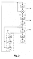
- FIG. figure 2 A flowchart of the method implemented by the system just described is illustrated in FIG. figure 2 .
- This flow chart relates to the reading of a particular macropixel, the reading of the other macropixels being identical.
- a first step of the method according to the invention is a low-resolution reading step 50 of the macropixel.
- This step 50 comprises a substep 52 in which the macropixel is read at low resolution, that is to say that a spatial average of the values of its pixels is performed, and then the reading of a value of one pixel of it.
- a test is performed to determine if a condition for reading this macropixel in high resolution is satisfied. This condition is satisfied in particular if the absolute value of the difference between the low resolution value of the macropixel just read and the low resolution value previously stored is greater than the threshold value, in which case a movement is detected in the macropixel. . This condition is also satisfied if the macropixel belongs to a neighborhood of a macropixel in which motion has been detected.
- the substep 54 loops back on the substep 52 in order to continue scanning the occurrence of satisfying the high resolution playback mode enable condition.
- the low resolution step 50 continues with a correction initialization step 56 .
- This initialization step 56 comprises a sub-step of reading in high resolution of the macropixel, that is to say a reading of all its pixels, followed by a substep 60 of storage of the read pixel values, forming thus a reference macropixel.
- a step 62 for reading the macropixel in high resolution mode with noise correction thereof is then triggered.
- This step 62 includes a substep 64 for reading the macropixel in high resolution mode. Sub-step 64 is then followed by a substep 66 in which the difference between the values of the newly read pixels and the corresponding pixel values of the reference macropixel stored at 60 is formed.
- the step 62 of reading in high resolution mode with correction then continues with a substep 68 conversion of the difference thus formed into a digital macropixel.
- a step 70 of verifying the satisfaction of the activation condition of the high resolution reading mode is triggered following the substep 64 of reading in high resolution mode of the macropixel.
- This step 70 comprises a sub-step of reading the macropixel in the low resolution mode identical to the sub-step 62, and a substep of 74 of testing whether the reading condition in high resolution is still satisfied, the sub-step of step 74 being identical to the sub-step 54.
- the substep 74 loops on the step 62 for a new reading in high resolution mode with correction.
- substep 74 continues with a substep 76 in which it is tested whether the macropixel should be read in low resolution mode. More particularly, it is tested at 76 if at least one macropixel adjacent to the macropixel is being read at high resolution following the detection of a motion therein.
- the reading in the high resolution mode of the macropixel continues with the looping of the substep 76 on the step 62.
- the reading in low resolution mode of it is activated by the looping of the sub. step 76 on step 50.
- the figure 3 is an image of a scene from the detector without correction. As we can see, this image is unusable, at least visually.
- the figure 4 is an image of the same scene after application of the method according to the invention, the black blocks corresponding to macropixels in which no movement has been detected.
- macropixels in the vicinity of a macropixel in which motion has been detected are automatically read in high resolution mode with a correction according to the invention.
- macropixels recorded as a reference include the image of the moving target, which is then subtracted from the raw images read later. It can thus appear "ghost" objects or phenomena of drag in the corrected images consecutive.
- Activation of the high-resolution reading of a neighbor macropixel to that in which a motion has been detected has the effect of storing, for this neighboring macropixel, a reference macropixel which does not include any moving object.
- the reference macropixel stored thus corresponds only to the back of the stage.
- Step by step given the permanent refocusing of the high-resolution window on the detected object and the high-resolution passage of the macropixels upstream of the displacement of the object (by the principle of "lighting" neighboring macropixels) , so there is acquisition of references without presence of the object in macropixels and thus a prevention of ghost object appearances.
- the renewal of reference macropixels is here ensured by the movement of the targets themselves. This movement implies a sufficiently regular activation of the reading in high resolution mode so that the reference macropixels stored include the noise at the actual time of reading in high resolution.
- the reference macropixels for example to take account of very rapid variations in the dispersion of the detection characteristics of the detector. This can be the case, for example, if the observed scene is itself subjected to very rapid temperature variations (for example the abrupt input of an object that is substantially warmer than the background of the scene for example), or Detector manufacturing technology involves such rapid dispersion variation.
- the reference macropixels are digitized and stored in a digital memory.
- macropixels that have just been read are digitized and the difference between them and the reference macropixels is done in digital form. This makes it possible in particular to avoid phenomena of drift in time of the values of the reference macropixels usually observed when the storage is performed in analog form (presence for example of leakage in the capacitor bank used for analog storage).
- the storage in digital format of the reference macropixels is particularly useful when the object stagnates in part of the observed scene, in which case the renewal of reference macropixels is infrequent.
- the present invention applies to any type of detectors read at sub-resolution and having a dispersion of their detection characteristics.
- the present invention applies to the detection in the visible range, for example by means of a photosensitive semiconductor detector (matrix of photodiodes or matrix of phototransistors).
Landscapes
- Engineering & Computer Science (AREA)
- Multimedia (AREA)
- Signal Processing (AREA)
- Transforming Light Signals Into Electric Signals (AREA)
Claims (7)
- Verfahren zur Erfassung und Nachverfolgung von Objekten in einem Bilderstrom, der von einer zweidimensionalen Matrix (12) von Pixeln eines Sensors geliefert wird, wobei die Matrix in Pixelblöcke (16) eingeteilt ist, die Makropixel bilden, wobei jedes Makropixel unabhängig voneinander gemäß einem Modus hoher Auflösung und/oder einem Modus geringer Auflösung ausgelesen werden kann, wobei der Modus hoher Auflösung darin besteht, jedes Pixel des Makropixels so auszulesen, dass einzelne Pixelwerte hergestellt werden, und der Modus geringer Auflösung darin besteht, einen einzigen Wert für alle Pixel des Makropixels herzustellen, dadurch gekennzeichnet, dass es umfasst:■ einen Ausleseschritt (50) im Modus geringer Auflösung, der darin besteht, (in 52, 54) zu bestimmen, welche die Makropixel der Matrix sind, die im Modus hoher Auflösung ausgelesen werden, und welche die Makropixel der Matrix sind, die nur im Modus geringer Auflösung ausgelesen werden:o wobei alle Makropixel der Matrix im Modus geringer Auflösung ausgelesen werden (52);o wobei eine Bewegung in den Makropixeln in Abhängigkeit von den Werten der im Modus geringer Auflösung ausgelesenen Makropixel erfasst wird;○ wobei die Makropixel, in denen eine Bewegung erfasst wird, aktiviert oder im Modus hoher Auflösung gehalten werden;○ wobei der Modus hoher Auflösung für jedes Makropixel aktiviert wird, in dem keine Bewegung erfasst wird und das sich in einer Nachbarschaft eines Makropixels befindet, in dem eine Bewegung erfasst wird;○ wobei nur der Modus geringer Auflösung für die anderen Makropixel der Matrix aktiviert oder gehalten wird;■ einen Korrekturinitialisierungsschritt (56), der darin besteht, bei der Aktivierung (in 54) des Auslesemodus in hoher Auflösung für ein Makropixel die einzelnen Werte der Pixel von diesem auszulesen (in 58) und zu speichern (in 60), um ein Referenzmakropixel für das Makropixel zu definieren; und■ einen Ausleseschritt (62) im Modus hoher Auflösung, der darin besteht:○ im Modus hoher Auflösung die Makropixel auszulesen (in 62), für welche der Modus hoher Auflösung aktiviert ist;○ jeden einzelnen Pixelwert eines im Modus hoher Auflösung ausgelesenen Makropixels zu korrigieren, indem die Differenz zwischen dem Einzelwert und dem entsprechenden Wert des dem Makropixel zugeordneten Referenzmakropixels (in 66) gebildet wird; und○ die korrigierten einzelnen Pixelwerte der im Modus hoher Auflösung ausgelesenen Makropixel zu speichern und/oder anzuzeigen.
- Verfahren nach Anspruch 1, dadurch gekennzeichnet, dass eine Bewegung in einem bestimmten Makropixel erfasst wird, wenn die Werte, die bei zwei aufeinanderfolgenden Auslesungen im Modus geringer Auflösung dieses Makropixels ermittelt wurden, eine Schwankung aufweisen, die größer ist als ein vorbestimmter Schwellenwert.
- Vorrichtung zur Erfassung und Nachverfolgung von Objekten in einem Bilderstrom, der von einer zweidimensionalen Pixelmatrix (12) eines Bildsensors geliefert wird, wobei die Matrix in Pixelblöcke (16) eingeteilt ist, die Makropixel bilden, wobei der Sensor Einrichtungen (10) umfasst, um jedes Makropixel unabhängig voneinander gemäß einem Modus hoher Auflösung und/oder einem Modus geringer Auflösung auszulesen, wobei der Modus hoher Auflösung darin besteht, jedes Pixel des Makropixels so auszulesen, das einzelne Pixelwerte hergestellt werden, und der Modus geringer Auflösung darin besteht, einen einzigen Wert für alle Pixel des Makropixels herzustellen, dadurch gekennzeichnet, dass die Vorrichtung umfasst:■ Einrichtungen (24) zum Auslesen im Modus geringer Auflösung, die geeignet sind, zu bestimmen, welche die Makropixel der Matrix sind, die im Modus hoher Auflösung ausgelesen werden, und welche die Makropixel der Matrix sind, die nur im Modus geringer Auflösung ausgelesen werden:○ wobei alle Makropixel der Matrix im Modus geringer Auflösung ausgelesen werden;○ wobei eine Bewegung in den Makropixeln in Abhängigkeit von den Werten der im Modus geringer Auflösung ausgelesenen Makropixel erfasst wird;○ wobei die Makropixel, in denen eine Bewegung erfasst wird, aktiviert oder im Modus hoher Auflösung gehalten werden;○ wobei der Modus hoher Auflösung für jedes Makropixel aktiviert wird, in dem keine Bewegung erfasst wird und das sich in einer Nachbarschaft eines Makropixels befindet, in dem eine Bewegung erfasst wird;○ wobei nur der Modus geringer Auflösung für die anderen Makropixel der Matrix aktiviert oder gehalten wird;■ Korrekturinitialisierungseinrichtungen, die geeignet sind, bei der Aktivierung des Auslesemodus in hoher Auflösung für ein Makropixel die einzelnen Werte der Pixel von diesem auszulesen und zu speichern, um ein Referenzmakropixel für das Makropixel zu definieren; und■ Ausleseeinrichtungen im Modus hoher Auflösung, die umfassen:○ Einrichtungen zum Auslesen der Makropixel im Modus hoher Auflösung, für welche der Modus hoher Auflösung aktiviert ist;○ Einrichtungen, die geeignet sind, jeden einzelnen Pixelwert eines im Modus hoher Auflösung ausgelesenen Makropixels zu korrigieren, indem die Differenz zwischen dem Einzelwert und dem entsprechenden Wert des dem Makropixel zugeordneten Referenzmakropixels gebildet wird; und○ Einrichtungen zum Speichern und/oder Anzeigen der korrigierten einzelnen Pixelwerte der im Modus hoher Auflösung ausgelesenen Makropixel.
- Vorrichtung nach Anspruch 3, dadurch gekennzeichnet, dass die Korrektureinrichtungen (26, 28) in analoger Form realisiert sind.
- Vorrichtung nach Anspruch 4, dadurch gekennzeichnet, dass sie Einrichtungen (30) zur analogen/digitalen Umwandlung der gebildeten Differenz umfasst.
- Vorrichtung nach Anspruch 3, dadurch gekennzeichnet, dass sie Einrichtungen zur analogen/digitalen Umwandlung der für ein Pixel oder ein Makropixel ausgelesenen Werte umfasst.
- Vorrichtung nach Anspruch 6, dadurch gekennzeichnet, dass die Einrichtungen (26), die geeignet sind, die Werte der Pixel eines Makropixels zu speichern, ein digitaler Speicher sind, und dass die Einrichtungen (28) zum Bilden der Differenz aus einer digitalen Schaltung bestehen.
Applications Claiming Priority (1)
| Application Number | Priority Date | Filing Date | Title |
|---|---|---|---|
| FR0758792A FR2923339B1 (fr) | 2007-11-05 | 2007-11-05 | Procede de lecture d'une matrice bidimensielle de pixels et dispositif pour la mise en oeuvre d'un tel procede |
Publications (2)
| Publication Number | Publication Date |
|---|---|
| EP2056590A1 EP2056590A1 (de) | 2009-05-06 |
| EP2056590B1 true EP2056590B1 (de) | 2014-04-09 |
Family
ID=39466084
Family Applications (1)
| Application Number | Title | Priority Date | Filing Date |
|---|---|---|---|
| EP08305730.7A Not-in-force EP2056590B1 (de) | 2007-11-05 | 2008-10-27 | Verfahren und Vorrichtung zum Pixelsauslesen aus einer bidimensionalen Matrix |
Country Status (5)
| Country | Link |
|---|---|
| US (1) | US8284281B2 (de) |
| EP (1) | EP2056590B1 (de) |
| JP (1) | JP5264407B2 (de) |
| CN (1) | CN101431597B (de) |
| FR (1) | FR2923339B1 (de) |
Families Citing this family (17)
| Publication number | Priority date | Publication date | Assignee | Title |
|---|---|---|---|---|
| US9451183B2 (en) | 2009-03-02 | 2016-09-20 | Flir Systems, Inc. | Time spaced infrared image enhancement |
| US10244190B2 (en) | 2009-03-02 | 2019-03-26 | Flir Systems, Inc. | Compact multi-spectrum imaging with fusion |
| WO2012170946A2 (en) | 2011-06-10 | 2012-12-13 | Flir Systems, Inc. | Low power and small form factor infrared imaging |
| US9635285B2 (en) | 2009-03-02 | 2017-04-25 | Flir Systems, Inc. | Infrared imaging enhancement with fusion |
| US10091439B2 (en) | 2009-06-03 | 2018-10-02 | Flir Systems, Inc. | Imager with array of multiple infrared imaging modules |
| KR101686079B1 (ko) * | 2010-12-27 | 2016-12-13 | 삼성전자주식회사 | 깊이 영상 생성 장치 및 방법 |
| US9143703B2 (en) | 2011-06-10 | 2015-09-22 | Flir Systems, Inc. | Infrared camera calibration techniques |
| WO2014105897A1 (en) * | 2012-12-26 | 2014-07-03 | Flir Systems, Inc. | Infrared detector array with selectable pixel binning systems and methods |
| US10051210B2 (en) | 2011-06-10 | 2018-08-14 | Flir Systems, Inc. | Infrared detector array with selectable pixel binning systems and methods |
| CN103875235B (zh) | 2011-06-10 | 2018-10-12 | 菲力尔系统公司 | 用于红外成像装置的非均匀性校正技术 |
| JP5772272B2 (ja) * | 2011-06-16 | 2015-09-02 | 富士通株式会社 | 情報処理装置、及び情報処理方法 |
| JP6594493B2 (ja) * | 2013-05-10 | 2019-10-23 | キヤノン株式会社 | 固体撮像装置およびカメラ |
| EP2838268B1 (de) | 2013-07-31 | 2019-02-20 | Axis AB | Verfahren, Vorrichtung und System zur Herstellung einer zusammengeführten digitalen Videosequenz |
| KR102357965B1 (ko) | 2015-01-12 | 2022-02-03 | 삼성전자주식회사 | 객체 인식 방법 및 장치 |
| US9819913B2 (en) * | 2015-08-26 | 2017-11-14 | Stmicroelectronics International N.V. | Image sensor device with macropixel processing and related devices and methods |
| US11445133B2 (en) | 2017-08-10 | 2022-09-13 | Robert Bosch Gmbh | Low power and low data-rate imager |
| WO2025054855A1 (en) * | 2023-09-13 | 2025-03-20 | Huawei Technologies Co., Ltd. | Image sensor |
Citations (5)
| Publication number | Priority date | Publication date | Assignee | Title |
|---|---|---|---|---|
| US5257058A (en) * | 1990-11-30 | 1993-10-26 | Canon Kabushiki Kaisha | Interchangeable lens system |
| US5703639A (en) * | 1994-10-25 | 1997-12-30 | Dalsa, Inc. | Charge coupled device pulse discriminator |
| US6366317B1 (en) * | 1998-03-27 | 2002-04-02 | Intel Corporation | Motion estimation using intrapixel logic |
| JP2004007089A (ja) * | 2002-05-30 | 2004-01-08 | Nippon Advantage Corp | 状態変化判定装置 |
| US7106374B1 (en) * | 1999-04-05 | 2006-09-12 | Amherst Systems, Inc. | Dynamically reconfigurable vision system |
Family Cites Families (25)
| Publication number | Priority date | Publication date | Assignee | Title |
|---|---|---|---|---|
| EP1650692A1 (de) * | 1998-11-02 | 2006-04-26 | DATALOGIC S.p.A. | Anordnung und Verfahren zur automatischen Erfassung und Verarbeitung von optischen Koden |
| JP3611507B2 (ja) * | 2000-05-30 | 2005-01-19 | 松下電器産業株式会社 | 動きベクトル検出装置 |
| JP4564190B2 (ja) * | 2001-03-06 | 2010-10-20 | 株式会社リコー | テレビ会議システムにおける画像入力に適したデジタルカメラ |
| US6714241B2 (en) * | 2001-04-25 | 2004-03-30 | Hewlett-Packard Development Company, L.P. | Efficient dark current subtraction in an image sensor |
| KR100792283B1 (ko) * | 2001-08-07 | 2008-01-07 | 삼성전자주식회사 | 이동물체 자동 추적장치 및 방법 |
| EP1345154A1 (de) * | 2002-03-11 | 2003-09-17 | Bracco Imaging S.p.A. | Verfahren zur Kodierung von Bildpunkten und Verfahren zur Bildverarbeitung das dazu geignet ist, eine qualitative Erkennung eines mit einem oder mehreren Bildpunkten reproduzierten Objektes zu führen |
| WO2003092276A1 (en) * | 2002-04-25 | 2003-11-06 | Sony Corporation | Image processing apparatus, image processing method, and image processing program |
| JP2004023310A (ja) * | 2002-06-14 | 2004-01-22 | Hitachi Ltd | 画像入力装置 |
| US7408572B2 (en) * | 2002-07-06 | 2008-08-05 | Nova Research, Inc. | Method and apparatus for an on-chip variable acuity imager array incorporating roll, pitch and yaw angle rates measurement |
| JP2004120341A (ja) * | 2002-09-26 | 2004-04-15 | Riosu Corp:Kk | 映像監視システム |
| EP1557840B1 (de) * | 2002-10-15 | 2012-12-05 | Sony Corporation | Speicherbaustein, bewegungsvektordetektionseinrichtung und detektionsverfahren |
| JP4084991B2 (ja) * | 2002-11-29 | 2008-04-30 | 富士通株式会社 | 映像入力装置 |
| US7486313B2 (en) * | 2003-01-17 | 2009-02-03 | Biomorphic Vlsi, Inc. | System and method for automatic exposure control and white balancing for CMOS sensors |
| US7015960B2 (en) * | 2003-03-18 | 2006-03-21 | Candela Microsystems, Inc. | Image sensor that uses a temperature sensor to compensate for dark current |
| US20050128327A1 (en) * | 2003-12-10 | 2005-06-16 | Bencuya Selim S. | Device and method for image sensing |
| US7619669B2 (en) * | 2003-12-29 | 2009-11-17 | Micron Technologies, Inc. | Power savings with multiple readout circuits |
| ATE374502T1 (de) * | 2004-02-18 | 2007-10-15 | St Microelectronics Srl | Verfahren zur digitalen bildverarbeitung mittels geordnetem dithering |
| US7483059B2 (en) * | 2004-04-30 | 2009-01-27 | Hewlett-Packard Development Company, L.P. | Systems and methods for sampling an image sensor |
| JP4230967B2 (ja) * | 2004-07-02 | 2009-02-25 | 富士通マイクロエレクトロニクス株式会社 | 撮像装置、撮像装置の制御方法、cmosイメージセンサ |
| US7876980B2 (en) * | 2004-11-11 | 2011-01-25 | Panasonic Corporation | Imaging apparatus and imaging method for outputting a specified number of pixels in a specified area |
| KR100660862B1 (ko) * | 2005-02-23 | 2006-12-26 | 삼성전자주식회사 | 동일 색상의 화소 데이터를 가산하여 출력하는 컬러 촬상장치 및 그 화소 데이터 독출 방법 |
| WO2006108210A1 (en) * | 2005-02-25 | 2006-10-19 | Kevin Liddiard | Microbolometer infrared security sensor |
| US7385171B2 (en) * | 2005-05-09 | 2008-06-10 | Sensors Unlimited, Inc. | Method and apparatus for providing enhanced resolution in photodetectors |
| JP2009516476A (ja) * | 2005-11-14 | 2009-04-16 | サーノフ コーポレーション | ハイブリッドのピクセル配列を有するcmosイメージ・センサ |
| CN100527792C (zh) * | 2006-02-07 | 2009-08-12 | 日本胜利株式会社 | 摄像方法以及摄像装置 |
-
2007
- 2007-11-05 FR FR0758792A patent/FR2923339B1/fr not_active Expired - Fee Related
-
2008
- 2008-10-14 US US12/250,720 patent/US8284281B2/en not_active Expired - Fee Related
- 2008-10-23 CN CN200810171783.4A patent/CN101431597B/zh not_active Expired - Fee Related
- 2008-10-23 JP JP2008273322A patent/JP5264407B2/ja not_active Expired - Fee Related
- 2008-10-27 EP EP08305730.7A patent/EP2056590B1/de not_active Not-in-force
Patent Citations (5)
| Publication number | Priority date | Publication date | Assignee | Title |
|---|---|---|---|---|
| US5257058A (en) * | 1990-11-30 | 1993-10-26 | Canon Kabushiki Kaisha | Interchangeable lens system |
| US5703639A (en) * | 1994-10-25 | 1997-12-30 | Dalsa, Inc. | Charge coupled device pulse discriminator |
| US6366317B1 (en) * | 1998-03-27 | 2002-04-02 | Intel Corporation | Motion estimation using intrapixel logic |
| US7106374B1 (en) * | 1999-04-05 | 2006-09-12 | Amherst Systems, Inc. | Dynamically reconfigurable vision system |
| JP2004007089A (ja) * | 2002-05-30 | 2004-01-08 | Nippon Advantage Corp | 状態変化判定装置 |
Also Published As
| Publication number | Publication date |
|---|---|
| FR2923339A1 (fr) | 2009-05-08 |
| CN101431597B (zh) | 2013-06-26 |
| CN101431597A (zh) | 2009-05-13 |
| FR2923339B1 (fr) | 2009-12-11 |
| US20090115877A1 (en) | 2009-05-07 |
| US8284281B2 (en) | 2012-10-09 |
| JP2009118476A (ja) | 2009-05-28 |
| EP2056590A1 (de) | 2009-05-06 |
| JP5264407B2 (ja) | 2013-08-14 |
Similar Documents
| Publication | Publication Date | Title |
|---|---|---|
| EP2056590A1 (de) | Leseverfahren einer zweidimensionalen Pixelmatrix und Vorrichtung zur Umsetzung eines solchen Verfahrens | |
| CA2633407C (fr) | Dispositif de detection de rayonnement electromagnetique, en particulier infrarouge | |
| CA2726821C (fr) | Dispositif et procede de detection d'un rayonnement infrarouge au moyen d'une matrice de bolometres resistifs | |
| CA2632505C (fr) | Dispositif de detection de rayonnement infrarouge a detecteurs bolometriques | |
| EP2071309B1 (de) | Vorrichtung zur Erkennung von Infrarotstrahlung, die ein bildgebendes Widerstandsbolometer umfasst, System, das eine Matrix solcher Bolometer umfasst und Verfahren zum Auslesen eines solchen Systems | |
| EP3140906B1 (de) | Vorrichtung mit hohem dynamikumfang zur integration eines elektrischen stroms | |
| FR2936052A1 (fr) | Dispositif pur la detection d'un rayonnement infrarouge comportant un bolometre resistif d'imagerie, systeme comprenant une matrice de tels bolometres, et procede de lecture d'un bolometre d'imagerie integre dans un tel system | |
| WO1992003016A2 (fr) | Camera panoramique du type a transfert de charges dans un systeme de veille | |
| EP2071310A1 (de) | Vorrichtung zur Erkennung von elektromagnetischer Strahlung, die ein bildgebendes Widerstandsbolometer umfasst, System, das eine Matrix solcher Vorrichtungen umfasst und Verfahren zum Auslesen eines solchen Systems | |
| EP2356810A1 (de) | Bildsensor mit doppelladungstransfer für grossen dynamikumfang und leseverfahren | |
| FR2574241A1 (fr) | Mesure du courant du noir pour des imageurs a transfert de trame | |
| JP2004523184A (ja) | 画像センサにおける効率的な暗電流の減算 | |
| EP3929550A1 (de) | Verfahren zur verarbeitung eines rohbildes, das von einem bolometer-detektor gesammelt wurde, und entsprechende vorrichtung | |
| WO2020221773A1 (fr) | Procede et dispositif pour retirer la remanence dans une image infrarouge d'une scene changeante | |
| EP4103921B1 (de) | Verfahren zum kalibrieren einer opto-ektronischen vorrichtung | |
| EP4176582A1 (de) | Verfahren zur erfassung von bildern einer szene | |
| FR2942074A1 (fr) | Dispositif pour la detection d'un rayonnement electromagnetique, et notamment infrarouge | |
| FR3100886A1 (fr) | Capteur infrarouge et procede de commande associe | |
| EP2294809B1 (de) | Bildsensor des tdi-typs mit selbstangepasster dynamik auf der basis des bildpunkts | |
| WO2024132928A1 (fr) | Circuit de lecture pour détecteur infrarouge | |
| EP3963540A1 (de) | Verfahren und vorrichtung zum entfernen von remanenz in einem infrarotbild einer statischen szene | |
| FR2941329A1 (fr) | Detecteur bispectral. | |
| FR2792149A1 (fr) | Procede de formation d'une image | |
| FR3048841A1 (fr) | Procede et dispositif de capture et de restitution d'image thermique | |
| FR2670645A1 (fr) | Procede et dispositif d'amelioration du rapport signal a bruit dans un dispositif a transfert de charges. |
Legal Events
| Date | Code | Title | Description |
|---|---|---|---|
| PUAI | Public reference made under article 153(3) epc to a published international application that has entered the european phase |
Free format text: ORIGINAL CODE: 0009012 |
|
| AK | Designated contracting states |
Kind code of ref document: A1 Designated state(s): AT BE BG CH CY CZ DE DK EE ES FI FR GB GR HR HU IE IS IT LI LT LU LV MC MT NL NO PL PT RO SE SI SK TR |
|
| AX | Request for extension of the european patent |
Extension state: AL BA MK RS |
|
| 17P | Request for examination filed |
Effective date: 20090630 |
|
| AKX | Designation fees paid |
Designated state(s): AT BE BG CH CY CZ DE DK EE ES FI FR GB GR HR HU IE IS IT LI LT LU LV MC MT NL NO PL PT RO SE SI SK TR |
|
| RAP1 | Party data changed (applicant data changed or rights of an application transferred) |
Owner name: COMMISSARIAT A L'ENERGIE ATOMIQUE ET AUX ENERGIES |
|
| 17Q | First examination report despatched |
Effective date: 20130226 |
|
| GRAP | Despatch of communication of intention to grant a patent |
Free format text: ORIGINAL CODE: EPIDOSNIGR1 |
|
| INTG | Intention to grant announced |
Effective date: 20131202 |
|
| GRAP | Despatch of communication of intention to grant a patent |
Free format text: ORIGINAL CODE: EPIDOSNIGR1 |
|
| INTG | Intention to grant announced |
Effective date: 20140127 |
|
| GRAS | Grant fee paid |
Free format text: ORIGINAL CODE: EPIDOSNIGR3 |
|
| GRAA | (expected) grant |
Free format text: ORIGINAL CODE: 0009210 |
|
| AK | Designated contracting states |
Kind code of ref document: B1 Designated state(s): AT BE BG CH CY CZ DE DK EE ES FI FR GB GR HR HU IE IS IT LI LT LU LV MC MT NL NO PL PT RO SE SI SK TR |
|
| REG | Reference to a national code |
Ref country code: GB Ref legal event code: FG4D Free format text: NOT ENGLISH |
|
| REG | Reference to a national code |
Ref country code: AT Ref legal event code: REF Ref document number: 661879 Country of ref document: AT Kind code of ref document: T Effective date: 20140415 Ref country code: CH Ref legal event code: EP |
|
| REG | Reference to a national code |
Ref country code: DE Ref legal event code: R082 Ref document number: 602008031367 Country of ref document: DE Representative=s name: MEISSNER BOLTE PATENTANWAELTE RECHTSANWAELTE P, DE Ref country code: DE Ref legal event code: R082 Ref document number: 602008031367 Country of ref document: DE Representative=s name: MEISSNER, BOLTE & PARTNER GBR, DE |
|
| REG | Reference to a national code |
Ref country code: IE Ref legal event code: FG4D Free format text: LANGUAGE OF EP DOCUMENT: FRENCH |
|
| REG | Reference to a national code |
Ref country code: DE Ref legal event code: R096 Ref document number: 602008031367 Country of ref document: DE Effective date: 20140522 |
|
| REG | Reference to a national code |
Ref country code: AT Ref legal event code: MK05 Ref document number: 661879 Country of ref document: AT Kind code of ref document: T Effective date: 20140409 |
|
| REG | Reference to a national code |
Ref country code: NL Ref legal event code: VDEP Effective date: 20140409 |
|
| REG | Reference to a national code |
Ref country code: LT Ref legal event code: MG4D |
|
| PG25 | Lapsed in a contracting state [announced via postgrant information from national office to epo] |
Ref country code: GR Free format text: LAPSE BECAUSE OF FAILURE TO SUBMIT A TRANSLATION OF THE DESCRIPTION OR TO PAY THE FEE WITHIN THE PRESCRIBED TIME-LIMIT Effective date: 20140710 Ref country code: BG Free format text: LAPSE BECAUSE OF FAILURE TO SUBMIT A TRANSLATION OF THE DESCRIPTION OR TO PAY THE FEE WITHIN THE PRESCRIBED TIME-LIMIT Effective date: 20140709 Ref country code: FI Free format text: LAPSE BECAUSE OF FAILURE TO SUBMIT A TRANSLATION OF THE DESCRIPTION OR TO PAY THE FEE WITHIN THE PRESCRIBED TIME-LIMIT Effective date: 20140409 Ref country code: NO Free format text: LAPSE BECAUSE OF FAILURE TO SUBMIT A TRANSLATION OF THE DESCRIPTION OR TO PAY THE FEE WITHIN THE PRESCRIBED TIME-LIMIT Effective date: 20140709 Ref country code: LT Free format text: LAPSE BECAUSE OF FAILURE TO SUBMIT A TRANSLATION OF THE DESCRIPTION OR TO PAY THE FEE WITHIN THE PRESCRIBED TIME-LIMIT Effective date: 20140409 Ref country code: IS Free format text: LAPSE BECAUSE OF FAILURE TO SUBMIT A TRANSLATION OF THE DESCRIPTION OR TO PAY THE FEE WITHIN THE PRESCRIBED TIME-LIMIT Effective date: 20140809 Ref country code: NL Free format text: LAPSE BECAUSE OF FAILURE TO SUBMIT A TRANSLATION OF THE DESCRIPTION OR TO PAY THE FEE WITHIN THE PRESCRIBED TIME-LIMIT Effective date: 20140409 |
|
| PG25 | Lapsed in a contracting state [announced via postgrant information from national office to epo] |
Ref country code: PL Free format text: LAPSE BECAUSE OF FAILURE TO SUBMIT A TRANSLATION OF THE DESCRIPTION OR TO PAY THE FEE WITHIN THE PRESCRIBED TIME-LIMIT Effective date: 20140409 Ref country code: HR Free format text: LAPSE BECAUSE OF FAILURE TO SUBMIT A TRANSLATION OF THE DESCRIPTION OR TO PAY THE FEE WITHIN THE PRESCRIBED TIME-LIMIT Effective date: 20140409 Ref country code: AT Free format text: LAPSE BECAUSE OF FAILURE TO SUBMIT A TRANSLATION OF THE DESCRIPTION OR TO PAY THE FEE WITHIN THE PRESCRIBED TIME-LIMIT Effective date: 20140409 Ref country code: LV Free format text: LAPSE BECAUSE OF FAILURE TO SUBMIT A TRANSLATION OF THE DESCRIPTION OR TO PAY THE FEE WITHIN THE PRESCRIBED TIME-LIMIT Effective date: 20140409 Ref country code: ES Free format text: LAPSE BECAUSE OF FAILURE TO SUBMIT A TRANSLATION OF THE DESCRIPTION OR TO PAY THE FEE WITHIN THE PRESCRIBED TIME-LIMIT Effective date: 20140409 Ref country code: SE Free format text: LAPSE BECAUSE OF FAILURE TO SUBMIT A TRANSLATION OF THE DESCRIPTION OR TO PAY THE FEE WITHIN THE PRESCRIBED TIME-LIMIT Effective date: 20140409 |
|
| PG25 | Lapsed in a contracting state [announced via postgrant information from national office to epo] |
Ref country code: PT Free format text: LAPSE BECAUSE OF FAILURE TO SUBMIT A TRANSLATION OF THE DESCRIPTION OR TO PAY THE FEE WITHIN THE PRESCRIBED TIME-LIMIT Effective date: 20140811 |
|
| REG | Reference to a national code |
Ref country code: DE Ref legal event code: R097 Ref document number: 602008031367 Country of ref document: DE |
|
| PG25 | Lapsed in a contracting state [announced via postgrant information from national office to epo] |
Ref country code: RO Free format text: LAPSE BECAUSE OF FAILURE TO SUBMIT A TRANSLATION OF THE DESCRIPTION OR TO PAY THE FEE WITHIN THE PRESCRIBED TIME-LIMIT Effective date: 20140409 Ref country code: DK Free format text: LAPSE BECAUSE OF FAILURE TO SUBMIT A TRANSLATION OF THE DESCRIPTION OR TO PAY THE FEE WITHIN THE PRESCRIBED TIME-LIMIT Effective date: 20140409 Ref country code: CZ Free format text: LAPSE BECAUSE OF FAILURE TO SUBMIT A TRANSLATION OF THE DESCRIPTION OR TO PAY THE FEE WITHIN THE PRESCRIBED TIME-LIMIT Effective date: 20140409 Ref country code: EE Free format text: LAPSE BECAUSE OF FAILURE TO SUBMIT A TRANSLATION OF THE DESCRIPTION OR TO PAY THE FEE WITHIN THE PRESCRIBED TIME-LIMIT Effective date: 20140409 Ref country code: SK Free format text: LAPSE BECAUSE OF FAILURE TO SUBMIT A TRANSLATION OF THE DESCRIPTION OR TO PAY THE FEE WITHIN THE PRESCRIBED TIME-LIMIT Effective date: 20140409 |
|
| PGFP | Annual fee paid to national office [announced via postgrant information from national office to epo] |
Ref country code: GB Payment date: 20141015 Year of fee payment: 7 Ref country code: DE Payment date: 20141010 Year of fee payment: 7 Ref country code: FR Payment date: 20141031 Year of fee payment: 7 |
|
| PLBE | No opposition filed within time limit |
Free format text: ORIGINAL CODE: 0009261 |
|
| STAA | Information on the status of an ep patent application or granted ep patent |
Free format text: STATUS: NO OPPOSITION FILED WITHIN TIME LIMIT |
|
| 26N | No opposition filed |
Effective date: 20150112 |
|
| PG25 | Lapsed in a contracting state [announced via postgrant information from national office to epo] |
Ref country code: IT Free format text: LAPSE BECAUSE OF FAILURE TO SUBMIT A TRANSLATION OF THE DESCRIPTION OR TO PAY THE FEE WITHIN THE PRESCRIBED TIME-LIMIT Effective date: 20140409 |
|
| REG | Reference to a national code |
Ref country code: DE Ref legal event code: R097 Ref document number: 602008031367 Country of ref document: DE Effective date: 20150112 |
|
| PG25 | Lapsed in a contracting state [announced via postgrant information from national office to epo] |
Ref country code: MC Free format text: LAPSE BECAUSE OF FAILURE TO SUBMIT A TRANSLATION OF THE DESCRIPTION OR TO PAY THE FEE WITHIN THE PRESCRIBED TIME-LIMIT Effective date: 20140409 Ref country code: LU Free format text: LAPSE BECAUSE OF FAILURE TO SUBMIT A TRANSLATION OF THE DESCRIPTION OR TO PAY THE FEE WITHIN THE PRESCRIBED TIME-LIMIT Effective date: 20141027 |
|
| REG | Reference to a national code |
Ref country code: CH Ref legal event code: PL |
|
| PG25 | Lapsed in a contracting state [announced via postgrant information from national office to epo] |
Ref country code: BE Free format text: LAPSE BECAUSE OF NON-PAYMENT OF DUE FEES Effective date: 20141031 |
|
| REG | Reference to a national code |
Ref country code: IE Ref legal event code: MM4A |
|
| PG25 | Lapsed in a contracting state [announced via postgrant information from national office to epo] |
Ref country code: SI Free format text: LAPSE BECAUSE OF FAILURE TO SUBMIT A TRANSLATION OF THE DESCRIPTION OR TO PAY THE FEE WITHIN THE PRESCRIBED TIME-LIMIT Effective date: 20140409 Ref country code: CH Free format text: LAPSE BECAUSE OF NON-PAYMENT OF DUE FEES Effective date: 20141031 Ref country code: LI Free format text: LAPSE BECAUSE OF NON-PAYMENT OF DUE FEES Effective date: 20141031 |
|
| PG25 | Lapsed in a contracting state [announced via postgrant information from national office to epo] |
Ref country code: IE Free format text: LAPSE BECAUSE OF NON-PAYMENT OF DUE FEES Effective date: 20141027 |
|
| REG | Reference to a national code |
Ref country code: DE Ref legal event code: R119 Ref document number: 602008031367 Country of ref document: DE |
|
| GBPC | Gb: european patent ceased through non-payment of renewal fee |
Effective date: 20151027 |
|
| PG25 | Lapsed in a contracting state [announced via postgrant information from national office to epo] |
Ref country code: CY Free format text: LAPSE BECAUSE OF FAILURE TO SUBMIT A TRANSLATION OF THE DESCRIPTION OR TO PAY THE FEE WITHIN THE PRESCRIBED TIME-LIMIT Effective date: 20140409 |
|
| PG25 | Lapsed in a contracting state [announced via postgrant information from national office to epo] |
Ref country code: GB Free format text: LAPSE BECAUSE OF NON-PAYMENT OF DUE FEES Effective date: 20151027 Ref country code: HU Free format text: LAPSE BECAUSE OF FAILURE TO SUBMIT A TRANSLATION OF THE DESCRIPTION OR TO PAY THE FEE WITHIN THE PRESCRIBED TIME-LIMIT; INVALID AB INITIO Effective date: 20081027 Ref country code: DE Free format text: LAPSE BECAUSE OF NON-PAYMENT OF DUE FEES Effective date: 20160503 Ref country code: MT Free format text: LAPSE BECAUSE OF FAILURE TO SUBMIT A TRANSLATION OF THE DESCRIPTION OR TO PAY THE FEE WITHIN THE PRESCRIBED TIME-LIMIT Effective date: 20140409 Ref country code: TR Free format text: LAPSE BECAUSE OF FAILURE TO SUBMIT A TRANSLATION OF THE DESCRIPTION OR TO PAY THE FEE WITHIN THE PRESCRIBED TIME-LIMIT Effective date: 20140409 |
|
| REG | Reference to a national code |
Ref country code: FR Ref legal event code: ST Effective date: 20160630 |
|
| PG25 | Lapsed in a contracting state [announced via postgrant information from national office to epo] |
Ref country code: FR Free format text: LAPSE BECAUSE OF NON-PAYMENT OF DUE FEES Effective date: 20151102 |