EP2056625A2 - Prothèse auditive, en particulier prothèse auditive placée derrière l'oreille - Google Patents
Prothèse auditive, en particulier prothèse auditive placée derrière l'oreille Download PDFInfo
- Publication number
- EP2056625A2 EP2056625A2 EP08105041A EP08105041A EP2056625A2 EP 2056625 A2 EP2056625 A2 EP 2056625A2 EP 08105041 A EP08105041 A EP 08105041A EP 08105041 A EP08105041 A EP 08105041A EP 2056625 A2 EP2056625 A2 EP 2056625A2
- Authority
- EP
- European Patent Office
- Prior art keywords
- hearing aid
- sound tube
- sound
- tube
- connector
- Prior art date
- Legal status (The legal status is an assumption and is not a legal conclusion. Google has not performed a legal analysis and makes no representation as to the accuracy of the status listed.)
- Withdrawn
Links
Images

Classifications
-
- H—ELECTRICITY
- H04—ELECTRIC COMMUNICATION TECHNIQUE
- H04R—LOUDSPEAKERS, MICROPHONES, GRAMOPHONE PICK-UPS OR LIKE ACOUSTIC ELECTROMECHANICAL TRANSDUCERS; ELECTRIC HEARING AIDS; PUBLIC ADDRESS SYSTEMS
- H04R25/00—Electric hearing aids
- H04R25/60—Mounting or interconnection of hearing aid parts, e.g. inside tips, housings or to ossicles
-
- H—ELECTRICITY
- H04—ELECTRIC COMMUNICATION TECHNIQUE
- H04R—LOUDSPEAKERS, MICROPHONES, GRAMOPHONE PICK-UPS OR LIKE ACOUSTIC ELECTROMECHANICAL TRANSDUCERS; ELECTRIC HEARING AIDS; PUBLIC ADDRESS SYSTEMS
- H04R2225/00—Details of deaf aids covered by H04R25/00, not provided for in any of its subgroups
- H04R2225/021—Behind the ear [BTE] hearing aids
- H04R2225/0213—Constructional details of earhooks, e.g. shape, material
-
- H—ELECTRICITY
- H04—ELECTRIC COMMUNICATION TECHNIQUE
- H04R—LOUDSPEAKERS, MICROPHONES, GRAMOPHONE PICK-UPS OR LIKE ACOUSTIC ELECTROMECHANICAL TRANSDUCERS; ELECTRIC HEARING AIDS; PUBLIC ADDRESS SYSTEMS
- H04R25/00—Electric hearing aids
- H04R25/60—Mounting or interconnection of hearing aid parts, e.g. inside tips, housings or to ossicles
- H04R25/607—Mounting or interconnection of hearing aid parts, e.g. inside tips, housings or to ossicles of earhooks
-
- Y—GENERAL TAGGING OF NEW TECHNOLOGICAL DEVELOPMENTS; GENERAL TAGGING OF CROSS-SECTIONAL TECHNOLOGIES SPANNING OVER SEVERAL SECTIONS OF THE IPC; TECHNICAL SUBJECTS COVERED BY FORMER USPC CROSS-REFERENCE ART COLLECTIONS [XRACs] AND DIGESTS
- Y10—TECHNICAL SUBJECTS COVERED BY FORMER USPC
- Y10T—TECHNICAL SUBJECTS COVERED BY FORMER US CLASSIFICATION
- Y10T29/00—Metal working
- Y10T29/49—Method of mechanical manufacture
- Y10T29/4957—Sound device making
- Y10T29/49572—Hearing aid component making
Definitions
- the invention relates to a hearing aid, in particular a behind-the-ear hearing aid with a receiver and a connector. Furthermore, the invention relates to a method for mounting a hearing aid, in particular a behind-the-ear hearing aid.
- Hearing devices generally have a housing in which a microphone, an amplifier device, a receiver and a power supply, usually a zinc-air battery, are arranged.
- the handset is connected to an acoustic output of the housing to output the acoustic signals processed and generated by the hearing aid.
- BTE hearing aids Behind the ear portable hearing aids (hereinafter referred to as BTE hearing aids) are usually held by a carrying hook behind the ear of a hearing aid wearer.
- the carrying hook In addition to the holder of the BTE hearing aid, the carrying hook usually fulfills another function.
- the carrying hook is traversed by a sound conductor, through which the sound generated by the earpiece of the BTE hearing device is transported to a sound tube connected to the front end of the carrying hook and forwarded by the earpiece into an auditory canal of the hearing device wearer.
- the carrying hook consists of a bent titanium tube which is partially encapsulated by a plastic material.
- This Titanium Tube is routed through the earhook inside the BTE Hearing Aid to the front of the Carrying Hook. For a fastening of the titanium tube in the housing of the BTE, this has in a region between the actual housing of the BTE hearing aid and the carrying hook a plastic retaining tab, by means of which the titanium tube is fixed on / in the BTE hearing aid.
- Such a hearing aid may have a slim design in the transition region between the housing of the BTE hearing aid and the carrying hook, but it is always necessary to open the housing of the hearing aid for replacement of the carrying hook. Furthermore, a screw connection of the carrying hook to the housing of the BTE hearing aid is not feasible.
- BTE hearing aids are known with a metal fitting for a carrying hook, which have a thread on a front, on the housing of the BTE hearing aid protruding portion. On the thread of the carrying hook can be screwed, which allows a simple replacement of the carrying hook in case of repair.
- the connector has an integral sound conduit, which opens into the receiver of the hearing aid.
- BTE hearing aids By adapting the BTE hearing aids to different hearing damage, z. B. due to different levels of performance, as well as for cosmetic reasons and also to increase the wearing comfort, as small as possible and small housing designs are preferred in BTE hearing aids.
- the curvatures in a range of different BTE hearing aids change, on which the carrying hook can be provided. Therefore, different metal fittings are required for different BTE hearing aids, because there is a fixed angle between a terminal area for the carrying hook and the sound conduit of the metal terminal, which depends on the particular curvature within a specific BTE hearing aid.
- the DE 10 2006 004 033 A1 discloses a BTE hearing aid, in particular a micro-size high-end hearing aid, with an insertable into an inner ear earmold.
- the BTE hearing aid is acoustically connected thereto by means of a sound tube via a sound tube fastening element of the otoplastic.
- the sound tube is so connected to the BTE hearing aid that it can be quickly and easily replaced.
- the object of the invention is achieved by means of a hearing aid, in particular by means of a BTE hearing aid, according to claim 1 and by a method for (pre) mounting a hearing aid, in particular a BTE hearing aid, according to claim 15.
- the bridging connector is preferably designed as a, at least in a longitudinal center section flexible, sound tube; d. H. the longitudinal center section of the sound tube is flexible in a direction perpendicular to its longitudinal direction.
- the sound signal generated by the hearing aid of the hearing aid is transported via the sound tube, which is bendable at least in the longitudinal center section, to the standardized connecting piece, wherein the connecting piece is fixedly connected to a housing of the hearing aid.
- a carrying hook can be releasably attached.
- An inventive method for (pre) mounting a hearing aid is carried out such that first a longitudinal end portion of the sound tube is mounted on the connector or the handset of the hearing aid. Subsequently, the this longitudinal end portion opposite longitudinal end portion of the sound tube is attached to the handset or on the connector, wherein the handset and / or connector can already be mounted in the housing of the hearing aid. Depending on whether no, one or both components (receiver, connector) are already installed in the hearing aid, the sound tube in accordance with the invention mounting method is bent or bent accordingly.
- connection piece is produced, and the different angle with different hearing aid devices is compensated or bridged by the sound tube.
- the sound tube over its entire extension in a longitudinal direction, in particular in a direction perpendicular to its longitudinal direction, formed flexible or flexible.
- the sound tube is continuously bendable along its entire longitudinal extension in a direction perpendicular thereto. Ie. within the hearing aid, the sound tube is then recorded kink-free, which can be the sound signal from the handset to the connector well, lossless and possible low-reflection transport.
- the sound tube is elastically deformable such that by means of this elastic deformability of the angle between the mounting position of the connector and the mounting position of the listener can be bridged. Furthermore, this can also be done by a plastic deformability of the hose. In this case, it is particularly preferred that this plastic deformability can be reversed again in such a way that the sound tube can be brought back into its original position or its original configuration. Ie. the sound tube is in such embodiments of the invention as possible reversibly plastically deformable.
- the sound tube when bridging the distance between the receiver and the connection piece, ie in its curved position, maintains essentially the same cross-section with respect to a non-bent position substantially in all cross-sections.
- This relates in particular to inner, preferably circular, configured cross sections of the sound tube through which the sound signal passes.
- the sound tube has a mesh, preferably a wire mesh, which gives the sound tube a certain (cross-sectional) stability.
- a flexibility of the sound tube can be influenced. If the braid is plastically deformed, then preferably the sound tube is plastically deformed. The same applies to an elastic deformation of the braid.
- At least the front portion of the connecting piece according to the invention which preferably has a screw connection for the carrying hook, is made of a metal or a metal alloy.
- the entire connector according to the invention is formed from metal or a metal alloy.
- the sound tube according to the invention between the connector according to the invention and the receiver of the hearing aid is preferably made of a plastic.
- the sound tube can be bent at any angle and thus universally applicable in any hearing aid.
- the flexible plastic sound tube is simply placed on / in the connector and thereby fixed, and then bent depending on the angle to the listener and also fixed there. Of course, this can be reversed kinematically; ie the plastic sound tube can first be placed on / in the receiver and thereby fixed and then attached only with the connector.
- a respective installation of the sound tube on / in the connector or on / in the handset can be done via a plug and / or an adhesive connection. It is possible to put the sound tube on a projection of the connector and / or a projection of the listener; conversely, it is of course possible to insert the sound tube in a recess in the connector and / or a recess in the handset. A mixed form of fortifications is of course also applicable.
- the material connector integrally formed in the prior art metal connector can only a single angle between the mounting position of the metal connector and the mounting position of the listener. According to the invention, this angle is not limited to a single one by the use of the plastic sound tube, but with the plastic sound tube according to the invention a plurality of angles can be bridged accordingly, ie desired angles can be laid according to the invention without problems. It is therefore necessary for almost all hearing aids of a type or series only a standardized connector and the flexible plastic sound tube, both of which can be used in all hearing aids. A single adaptation is possibly still necessary at a length of the plastic sound tube.
- BTE hearing aid worn behind the ear - hereinafter referred to as BTE hearing aid.
- the invention should not be limited only to such BTE hearing aids, but quite generally applicable to hearing aid devices; So also devices affect that not only serve to improve a hearing impairment, but are also suitable hearing a Höragistechnikloss in an acoustically difficult situation - such. B. on a construction site - to improve. This concerns z. As a hearing protection with integrated radio.
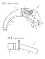
- Fig. 1 shows a side view of an upper portion of a housing 2 of a BTE hearing aid 1 according to the prior art.
- the upper portion of the housing 2 is continuously in a carrying hook 40, which is composed of a titanium tube 42 and a plastic extrusion 41.
- the titanium tube 42 For fastening the carrying hook 40 or the titanium tube 42, the titanium tube 42 has a connecting lug 43, which is likewise produced by a plastic extrusion coating of the titanium tube 42.
- the titanium tube 42 is further attached to a rear end facing away from the support hook 40 by a holding element 44 in the housing 2 of the BTE hearing aid 1.
- a disadvantage of such an embodiment of a BTE hearing aid 1 according to the prior art is that the titanium tube 42 is not connected to a mounting portion, such as. As a thread can be provided, by means of which the BTE hearing aid 1 and the support hook 40 can be easily connected to each other. It is therefore not possible, a releasable connection of the support hook 40 in the transition region to create the housing 2 of the BTE hearing aid 1. For replacement of the carrying hook 40, the housing 2 of the BTE hearing aid 1 must be opened. Furthermore, in such an embodiment, the carrying hook 40 is completely traversed by the titanium tube 42, which prevents a transparent embodiment of the carrying hook 40.
- Fig. 2 shows a solution according to the prior art, wherein a releasable attachment of a carrying hook is realized at an upper portion of a housing of a BTE hearing aid (all in the Fig. 2 not shown).
- the attachment of the carrying hook takes place at a consisting of a metal or a metal alloy connector 30 which can be installed in the upper part of the housing of the BTE hearing aid.
- the metal connector 30 is provided at its front, protruding from the BTE hearing aid section with an external thread 32 to which the carrying hook can be screwed.
- the carrying hook 40 is not as in the Fig. 1 constructed and has a male thread 32 of the connector 30 corresponding internal thread.
- the metal connection piece 30 has a sound conductor 34, which is formed materially in one piece with the section of the connection piece protruding from the BTE hearing device.
- the sound pipe 34 is provided at a certain angle relative to the remaining metal connector 30. This angle is adapted to a curvature of a respective area of the BTE hearing device.
- a free end of the sound conduit 34 is acoustically connected to a listener of the BTE hearing aid.
- a particular disadvantage here is that, depending on the BTE hearing aid different curvatures in the area of the BTE hearing aid for the metal connector 30 exist, so that the metal connector 30 must be individually adapted to the BTE hearing aid in question series.
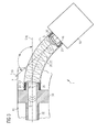
- Fig. 3 shows an inventive arrangement of a receiver 10 and a connector 30, which are acoustically coupled to each other via a sound tube 20 according to the invention.
- the earpiece 10 is arranged within a housing 2 of a BTE hearing aid 1 according to the invention, and the connection piece 30 forms, with a section provided outside the housing 2, a mechanical connection for a wearing hook 40 which rests on a thread 32 of the section or the connecting piece 30 is screwable.
- the sound tube 20 can be connected according to the invention with the handset 10 and / or the connector 30.
- sound signals S which are generated by the handset 10, from the handset 10 to the connector 30 and from there into the carrying hook 40 transportable.
- the sound tube 20 is designed such that it can bridge different arrangements of the receiver 10 and the connection piece 30. Ie. - Apart from a length of the sound tube 20 - this should be such that it can acoustically couple differently positioned connector / receiver configurations 30/10.
- variable angle ⁇ which illustrates the angle ⁇ between the longitudinal ends 21, 23 and the longitudinal end portions 21, 23 of the sound tube 20. This corresponds in an installed position of the sound tube 20 and the angle ⁇ between a longitudinal center line L 10 of the earphone 10 and a longitudinal center line L 30 of the connector 30th
- the sound tube 20 is flexurally flexible, at least in a longitudinal center section 22. This In particular, a direction perpendicular to its longitudinal direction L.
- An acoustic connection between the receiver 10 and connector 30 is preferably carried out as follows: First, a longitudinal end portion 21, 23 of the sound tube 20 at the connector 30 or the handset 10 is mounted. This can be z. B. directly after the preparation of the connector 30 or directly after an installation of the handset 10. However, it is also possible to make this only when assembling the BTE hearing aid 1. Thereafter, the sound tube 20 is mounted on the handset 10 and the connector 30 by the sound tube 20 is accordingly bent onto the handset 10 or the connector 30 and then attached thereto.
- the receiver 10 and the connection piece 30 within the BTE hearing aid 1 and subsequently to fasten the sound tube 20 on / in the relevant part (receiver 10, connection piece 30).
- a partial assembly that is to say initially an installation of the earphone 10 or the connecting piece 30 in the BTE hearing aid 1, and a subsequent mounting of the sound tube 20 with the fitting 30 or the earpiece 10 provided thereon or the earpiece 10 is, of course, possible.
- the entire sound tube 20 or its longitudinal center section 22 is continuously bendable, as a result of which the mounted sound tube 20 or its longitudinal center section 22 is guided without kinking within the BTE hearing device 1.
- the entire sound tube 20 or its longitudinal center section 22 within the BTE hearing aid 1 is continuously bent and has - preferably apart from one or both mounting portions 26 of the sound tube 20 on the handset 10 or the connector 30 - a curved course.
- the sound tube preferably has 20 in the BTE hearing aid 1 mounted state no linear course.
- the sound tube 20 or its longitudinal center section 22 is elastically and / or plastically deformable in the region between the mounting sections 26. This relates in particular to the direction perpendicular to the longitudinal direction L of the sound tube 20.
- the sound tube 20 is preferably configured such that it essentially retains at least one inner, acoustic cross-section during bending.
- the sound tube 20 or its longitudinal center section 22 is plastically deformable.
- the sound tube 20 or its longitudinal center section 22 is designed in such a way that, during plastic bending, at least the inner cross section of the sound tube 20 is essentially retained and as little elastic recovery as possible occurs.
- a stiffening element 25 extends at least in sections in the longitudinal direction L on / within the wall 24.
- the stiffening element 25 is formed as a braid 25 within the sound tube 20, in particular as a wire mesh 25.
- the braid 25 is elastically and / or plastically deformable when the sound tube 20 is bent.
- the braid 25 is plastically deformable even at low deflections or low degrees of deformation of the sound tube 20, so that the sound tube 20 is replaced by the braid 25 its plastic deformability.
- the braid 25 is preferred suitable for substantially maintaining its inner cross-section when bending the sound tube 20.
- the sound tube 20 can be firmly connected by means of a plug and / or adhesive connection with the connector 30 and / or the handset 10. In this case, it is possible to attach the sound tube 20 to a relevant connection section 16, 36 of the receiver 10 or of the connection piece 30 and, if necessary, to glue it to this connection. However, it is also possible to omit such a connection piece 16, 36 and to insert the sound tube 20 with its relevant mounting portion 26 in the handset 10 and in the connector 30 and to attach there accordingly.
- the handset 10 and / or the connector 30 at least one projection 17, 37 which holds the sound tube 20 additionally or fixed. Preference is given to the respective projection 17, 37 completely encircling.
- the sound tube 20 can be fixedly connected to the receiver 10 or the connecting piece 30 without having to use adhesive. Another advantage is that, in contrast to an attachment by means of adhesive greater manufacturing tolerances in the production of the sound tube 20 and the corresponding terminal portion 16, 36 are possible. Furthermore, it is advantageous that the sound tube 20 can be easily detached from the handset 10 or the connecting piece 30 for cleaning.
- Fig. 4 shows an embodiment with at least one, preferably outer circumferential projection 17, 37 at the respective terminal portion 16, 36.
- this projection 17, 37 of the sound tube 20 is pushed away during its mounting on the handset 10 and the connector 30.
- a plurality of such projections 17, 37 may be provided.
- Fig. 5 shows further embodiments of a fastening according to the invention of the sound tube 20 on the handset 10 and the connecting piece 30.
- a projection 17, 37 of the corresponding connection portion 16, 36 engages in a recess 27 of the sound tube 20 a.
- This recess 27 is formed corresponding to the respective projection 17, 37.
- the recess 27 is formed as a triangular in cross-section, preferably inside the sound tube 20 completely circumferential groove.
- the projection 17, 37 is formed as a projection 17, 37 running around the outside of the relevant connection section 16, 36, which is also triangular in a cross section.
- this can also be designed vice versa, which should also apply to the other embodiments of the invention.
- Fig. 5 an inside formed on the sound tube 20 projection 28, which is preferably also provided completely encircling.
- the projection 28 is rounded. This projection 28 engages in a preferably completely circumferential recess 18, 38 of the receiver 10 and the connecting piece 30, which is formed in the illustrated embodiment as a groove which is triangular in cross-section.
- the embodiments of the 4 and 5 are freely combinable with each other or can be used multiple times.
- it is not absolutely necessary - like on the right in Fig. 5 shown - corresponding profiles of the projection 17, 37; 28 and the recess 27; 18, 38 provide. It is only necessary to ensure that a certain clamping action ( Fig. 4 ) or a positive and / or non-positive connection between the sound tube 20 and the corresponding terminal portion 16, 36 is produced.
Landscapes
- Health & Medical Sciences (AREA)
- General Health & Medical Sciences (AREA)
- Neurosurgery (AREA)
- Otolaryngology (AREA)
- Physics & Mathematics (AREA)
- Engineering & Computer Science (AREA)
- Acoustics & Sound (AREA)
- Signal Processing (AREA)
- Details Of Connecting Devices For Male And Female Coupling (AREA)
- Headphones And Earphones (AREA)
- Details Of Audible-Bandwidth Transducers (AREA)
Applications Claiming Priority (1)
| Application Number | Priority Date | Filing Date | Title |
|---|---|---|---|
| DE102007052648A DE102007052648A1 (de) | 2007-11-05 | 2007-11-05 | Hörhilfsgerät, insbesondere HdO-Hörgerät |
Publications (2)
| Publication Number | Publication Date |
|---|---|
| EP2056625A2 true EP2056625A2 (fr) | 2009-05-06 |
| EP2056625A3 EP2056625A3 (fr) | 2013-01-09 |
Family
ID=40336175
Family Applications (1)
| Application Number | Title | Priority Date | Filing Date |
|---|---|---|---|
| EP08105041A Withdrawn EP2056625A3 (fr) | 2007-11-05 | 2008-08-14 | Prothèse auditive, en particulier prothèse auditive placée derrière l'oreille |
Country Status (3)
| Country | Link |
|---|---|
| US (1) | US20090116673A1 (fr) |
| EP (1) | EP2056625A3 (fr) |
| DE (1) | DE102007052648A1 (fr) |
Families Citing this family (5)
| Publication number | Priority date | Publication date | Assignee | Title |
|---|---|---|---|---|
| DE102010007609A1 (de) * | 2010-02-11 | 2011-08-11 | Siemens Medical Instruments Pte. Ltd. | Hörerschlauch mit Zugentlastung sowie Hörhilfe |
| DE102010041524A1 (de) * | 2010-09-28 | 2012-02-02 | Siemens Medical Instruments Pte. Ltd. | Hörhilfeapparat mit elastischem Hörerschlauch |
| DE102019202651A1 (de) | 2019-02-27 | 2020-01-23 | Sivantos Pte. Ltd. | Schallschlauch und HdO-Hörgerät |
| CN109862499A (zh) * | 2019-04-03 | 2019-06-07 | 惠州市锦好医疗科技股份有限公司 | 高性能声电转换模组、大功率助听器模块及耳背式助听器 |
| US12101604B2 (en) | 2019-08-15 | 2024-09-24 | Starkey Laboratories, Inc. | Systems, devices and methods for fitting hearing assistance devices |
Citations (1)
| Publication number | Priority date | Publication date | Assignee | Title |
|---|---|---|---|---|
| DE102006004033A1 (de) | 2006-01-27 | 2007-08-09 | Siemens Audiologische Technik Gmbh | Otoplastik mit Schallschlauchbefestigungselement |
Family Cites Families (20)
| Publication number | Priority date | Publication date | Assignee | Title |
|---|---|---|---|---|
| US2754365A (en) * | 1952-09-15 | 1956-07-10 | Maico Company Inc | Acoustical tone control for wearable hearing aids |
| US2939923A (en) * | 1955-08-03 | 1960-06-07 | John D Henderson | Hearing aid plastic ear pieces |
| USRE26174E (en) * | 1961-12-05 | 1967-03-21 | Leale hearing aid | |
| US3368644A (en) * | 1966-03-28 | 1968-02-13 | John D. Henderson | Hearing aid tone tuning device and method |
| CH648172A5 (en) * | 1979-06-12 | 1985-02-28 | Minisonic Ag | Hearing-aid to be worn in the ear |
| DE8316771U1 (de) * | 1983-06-08 | 1983-09-29 | Siemens AG, 1000 Berlin und 8000 München | Kleinhoergeraet |
| US5046580A (en) * | 1990-08-17 | 1991-09-10 | Barton James I | Ear plug assembly for hearing aid |
| US5195139A (en) * | 1991-05-15 | 1993-03-16 | Ensoniq Corporation | Hearing aid |
| US6681022B1 (en) * | 1998-07-22 | 2004-01-20 | Gn Resound North Amerca Corporation | Two-way communication earpiece |
| DE29819415U1 (de) * | 1998-10-30 | 1999-01-28 | Siemens Audiologische Technik Gmbh, 91058 Erlangen | Tragehaken für hinter dem Ohr tragbare Hörhilfegeräte |
| US6940988B1 (en) * | 1998-11-25 | 2005-09-06 | Insound Medical, Inc. | Semi-permanent canal hearing device |
| US6879696B1 (en) * | 2000-06-06 | 2005-04-12 | Phonak Ag | In-ear hearing aid and method for its manufacture |
| US7110562B1 (en) * | 2001-08-10 | 2006-09-19 | Hear-Wear Technologies, Llc | BTE/CIC auditory device and modular connector system therefor |
| US7522743B2 (en) * | 2002-01-07 | 2009-04-21 | Step Communications | High comfort sound delivery system |
| US7532733B2 (en) * | 2003-06-30 | 2009-05-12 | Siemens Hearing Instruments, Inc. | Feedback reducing receiver mount and assembly |
| DE102005036849A1 (de) * | 2005-08-04 | 2007-02-22 | Siemens Audiologische Technik Gmbh | Hörerschlauch mit Dämpfungselement und entsprechende Hörvorrichtung |
| DE102006029819A1 (de) * | 2006-06-28 | 2008-01-03 | Siemens Audiologische Technik Gmbh | Hörgerät mit einer Befestigung für einen Hörerschlauch |
| DE102007014131A1 (de) * | 2007-03-23 | 2008-09-25 | Siemens Audiologische Technik Gmbh | Hörgerät mit einer Befestigung eines Hörerschlauchs |
| DE102007044550A1 (de) * | 2007-09-18 | 2009-03-26 | Siemens Medical Instruments Pte. Ltd. | Schallkanal für eine Hörvorrichtung und entsprechendes Herstellungsverfahren |
| US8116495B2 (en) * | 2008-03-31 | 2012-02-14 | Starkey Laboratories, Inc. | Reinforced earbud device, system and method |
-
2007
- 2007-11-05 DE DE102007052648A patent/DE102007052648A1/de not_active Ceased
-
2008
- 2008-08-14 EP EP08105041A patent/EP2056625A3/fr not_active Withdrawn
- 2008-11-05 US US12/264,988 patent/US20090116673A1/en not_active Abandoned
Patent Citations (1)
| Publication number | Priority date | Publication date | Assignee | Title |
|---|---|---|---|---|
| DE102006004033A1 (de) | 2006-01-27 | 2007-08-09 | Siemens Audiologische Technik Gmbh | Otoplastik mit Schallschlauchbefestigungselement |
Also Published As
| Publication number | Publication date |
|---|---|
| US20090116673A1 (en) | 2009-05-07 |
| DE102007052648A1 (de) | 2009-05-07 |
| EP2056625A3 (fr) | 2013-01-09 |
Similar Documents
| Publication | Publication Date | Title |
|---|---|---|
| EP2116100B1 (fr) | Écouteur | |
| EP1061772B1 (fr) | Corps tubulaire de transmission sonore, notamment pour prothèses auditives | |
| EP1517170B1 (fr) | Prothèse auditive pouvant être montée sur une branche de lunettes | |
| EP1874093A2 (fr) | Appareil auditif doté d'une fixation pour un conduit auditif | |
| DE102007014131A1 (de) | Hörgerät mit einer Befestigung eines Hörerschlauchs | |
| DE10333293A1 (de) | Anschlussstück für Hörgerätetragehaken | |
| EP2056625A2 (fr) | Prothèse auditive, en particulier prothèse auditive placée derrière l'oreille | |
| EP2003930B1 (fr) | Appareil auditif doté d'un élément de raccordement fixé sur le cadre du boîtier | |
| EP2007172B1 (fr) | Petit tuyau de sortie acoustique doté d'une structure à 2 composants | |
| AT523938A4 (de) | Aufsteckbarer Ohrhörer-Adapter_CFC | |
| EP2043387A1 (fr) | Canal acoustique pour un dispositif d'écoute | |
| EP2360949A2 (fr) | Tuyau auditif avec décharge de traction et dispositif d'aide auditive | |
| EP0639932A2 (fr) | Prothèse auditive à porter derrière l'oreille | |
| EP1847868B1 (fr) | Appareil auditif derrière l'oreille incluant un adaptateur de lunette avec canal acoustique fin | |
| EP1909533A2 (fr) | Tube acoustique et dispositif auditif | |
| EP2278826A2 (fr) | Appareil d'aide auditive avec conduit auditif | |
| CH699444B1 (de) | Hörgerät. | |
| DE102007053834B4 (de) | Hörhilfsgerät, insbesondere HdO-Hörgerät | |
| EP1841287B1 (fr) | Prothèse auditive intra-auriculaire avec un élément de bande pour la fixation de la plaque frontale | |
| EP2866473B1 (fr) | Prothèse auditive, système auditif et procédé de montage d'un système auditif | |
| DE102005019994B4 (de) | Hörgerät | |
| DE102009014114B4 (de) | Hörgerätmodul und Hörbrille | |
| EP1443802A2 (fr) | Prothèse auditive placée derrière l'oreille | |
| DE29819415U1 (de) | Tragehaken für hinter dem Ohr tragbare Hörhilfegeräte | |
| EP1622421A2 (fr) | Dispositif auditif et son procédé de réalisation |
Legal Events
| Date | Code | Title | Description |
|---|---|---|---|
| PUAI | Public reference made under article 153(3) epc to a published international application that has entered the european phase |
Free format text: ORIGINAL CODE: 0009012 |
|
| AK | Designated contracting states |
Kind code of ref document: A2 Designated state(s): AT BE BG CH CY CZ DE DK EE ES FI FR GB GR HR HU IE IS IT LI LT LU LV MC MT NL NO PL PT RO SE SI SK TR |
|
| AX | Request for extension of the european patent |
Extension state: AL BA MK RS |
|
| PUAL | Search report despatched |
Free format text: ORIGINAL CODE: 0009013 |
|
| AK | Designated contracting states |
Kind code of ref document: A3 Designated state(s): AT BE BG CH CY CZ DE DK EE ES FI FR GB GR HR HU IE IS IT LI LT LU LV MC MT NL NO PL PT RO SE SI SK TR |
|
| AX | Request for extension of the european patent |
Extension state: AL BA MK RS |
|
| RIC1 | Information provided on ipc code assigned before grant |
Ipc: H04R 25/00 20060101AFI20121204BHEP |
|
| 17P | Request for examination filed |
Effective date: 20130705 |
|
| RBV | Designated contracting states (corrected) |
Designated state(s): AT BE BG CH CY CZ DE DK EE ES FI FR GB GR HR HU IE IS IT LI LT LU LV MC MT NL NO PL PT RO SE SI SK TR |
|
| AKX | Designation fees paid |
Designated state(s): AT BE BG CH CY CZ DE DK EE ES FI FR GB GR HR HU IE IS IT LI LT LU LV MC MT NL NO PL PT RO SE SI SK TR |
|
| 17Q | First examination report despatched |
Effective date: 20131016 |
|
| RAP1 | Party data changed (applicant data changed or rights of an application transferred) |
Owner name: SIVANTOS PTE. LTD. |
|
| STAA | Information on the status of an ep patent application or granted ep patent |
Free format text: STATUS: THE APPLICATION IS DEEMED TO BE WITHDRAWN |
|
| 18D | Application deemed to be withdrawn |
Effective date: 20160120 |