EP2057397B1 - Procédé de compression d'un raccord de compression et outil de presse associé - Google Patents
Procédé de compression d'un raccord de compression et outil de presse associé Download PDFInfo
- Publication number
- EP2057397B1 EP2057397B1 EP07802803.2A EP07802803A EP2057397B1 EP 2057397 B1 EP2057397 B1 EP 2057397B1 EP 07802803 A EP07802803 A EP 07802803A EP 2057397 B1 EP2057397 B1 EP 2057397B1
- Authority
- EP
- European Patent Office
- Prior art keywords
- pressing
- bead
- pressing portion
- section
- fitting
- Prior art date
- Legal status (The legal status is an assumption and is not a legal conclusion. Google has not performed a legal analysis and makes no representation as to the accuracy of the status listed.)
- Active
Links
Images







Classifications
-
- B—PERFORMING OPERATIONS; TRANSPORTING
- B21—MECHANICAL METAL-WORKING WITHOUT ESSENTIALLY REMOVING MATERIAL; PUNCHING METAL
- B21D—WORKING OR PROCESSING OF SHEET METAL OR METAL TUBES, RODS OR PROFILES WITHOUT ESSENTIALLY REMOVING MATERIAL; PUNCHING METAL
- B21D39/00—Application of procedures in order to connect objects or parts, e.g. coating with sheet metal otherwise than by plating; Tube expanders
- B21D39/04—Application of procedures in order to connect objects or parts, e.g. coating with sheet metal otherwise than by plating; Tube expanders of tubes with tubes; of tubes with rods
-
- F—MECHANICAL ENGINEERING; LIGHTING; HEATING; WEAPONS; BLASTING
- F16—ENGINEERING ELEMENTS AND UNITS; GENERAL MEASURES FOR PRODUCING AND MAINTAINING EFFECTIVE FUNCTIONING OF MACHINES OR INSTALLATIONS; THERMAL INSULATION IN GENERAL
- F16L—PIPES; JOINTS OR FITTINGS FOR PIPES; SUPPORTS FOR PIPES, CABLES OR PROTECTIVE TUBING; MEANS FOR THERMAL INSULATION IN GENERAL
- F16L13/00—Non-disconnectable pipe joints, e.g. soldered, adhesive, or caulked joints
- F16L13/14—Non-disconnectable pipe joints, e.g. soldered, adhesive, or caulked joints made by plastically deforming the material of the pipe, e.g. by flanging, rolling
- F16L13/141—Non-disconnectable pipe joints, e.g. soldered, adhesive, or caulked joints made by plastically deforming the material of the pipe, e.g. by flanging, rolling by crimping or rolling from the outside
-
- B—PERFORMING OPERATIONS; TRANSPORTING
- B21—MECHANICAL METAL-WORKING WITHOUT ESSENTIALLY REMOVING MATERIAL; PUNCHING METAL
- B21D—WORKING OR PROCESSING OF SHEET METAL OR METAL TUBES, RODS OR PROFILES WITHOUT ESSENTIALLY REMOVING MATERIAL; PUNCHING METAL
- B21D39/00—Application of procedures in order to connect objects or parts, e.g. coating with sheet metal otherwise than by plating; Tube expanders
- B21D39/04—Application of procedures in order to connect objects or parts, e.g. coating with sheet metal otherwise than by plating; Tube expanders of tubes with tubes; of tubes with rods
- B21D39/046—Connecting tubes to tube-like fittings
-
- B—PERFORMING OPERATIONS; TRANSPORTING
- B25—HAND TOOLS; PORTABLE POWER-DRIVEN TOOLS; MANIPULATORS
- B25B—TOOLS OR BENCH DEVICES NOT OTHERWISE PROVIDED FOR, FOR FASTENING, CONNECTING, DISENGAGING, OR HOLDING
- B25B27/00—Hand tools, specially adapted for fitting together or separating parts or objects whether or not involving some deformation, not otherwise provided for
- B25B27/02—Hand tools, specially adapted for fitting together or separating parts or objects whether or not involving some deformation, not otherwise provided for for connecting objects by press fit or detaching same
- B25B27/10—Hand tools, specially adapted for fitting together or separating parts or objects whether or not involving some deformation, not otherwise provided for for connecting objects by press fit or detaching same inserting fittings into hoses
-
- B—PERFORMING OPERATIONS; TRANSPORTING
- B30—PRESSES
- B30B—PRESSES IN GENERAL
- B30B1/00—Presses, using a press ram, characterised by the features of the drive therefor, pressure being transmitted directly, or through simple thrust or tension members only, to the press ram or platen
- B30B1/10—Presses, using a press ram, characterised by the features of the drive therefor, pressure being transmitted directly, or through simple thrust or tension members only, to the press ram or platen by toggle mechanism
-
- F—MECHANICAL ENGINEERING; LIGHTING; HEATING; WEAPONS; BLASTING
- F16—ENGINEERING ELEMENTS AND UNITS; GENERAL MEASURES FOR PRODUCING AND MAINTAINING EFFECTIVE FUNCTIONING OF MACHINES OR INSTALLATIONS; THERMAL INSULATION IN GENERAL
- F16L—PIPES; JOINTS OR FITTINGS FOR PIPES; SUPPORTS FOR PIPES, CABLES OR PROTECTIVE TUBING; MEANS FOR THERMAL INSULATION IN GENERAL
- F16L13/00—Non-disconnectable pipe joints, e.g. soldered, adhesive, or caulked joints
- F16L13/14—Non-disconnectable pipe joints, e.g. soldered, adhesive, or caulked joints made by plastically deforming the material of the pipe, e.g. by flanging, rolling
-
- F—MECHANICAL ENGINEERING; LIGHTING; HEATING; WEAPONS; BLASTING
- F16—ENGINEERING ELEMENTS AND UNITS; GENERAL MEASURES FOR PRODUCING AND MAINTAINING EFFECTIVE FUNCTIONING OF MACHINES OR INSTALLATIONS; THERMAL INSULATION IN GENERAL
- F16L—PIPES; JOINTS OR FITTINGS FOR PIPES; SUPPORTS FOR PIPES, CABLES OR PROTECTIVE TUBING; MEANS FOR THERMAL INSULATION IN GENERAL
- F16L13/00—Non-disconnectable pipe joints, e.g. soldered, adhesive, or caulked joints
- F16L13/14—Non-disconnectable pipe joints, e.g. soldered, adhesive, or caulked joints made by plastically deforming the material of the pipe, e.g. by flanging, rolling
- F16L13/141—Non-disconnectable pipe joints, e.g. soldered, adhesive, or caulked joints made by plastically deforming the material of the pipe, e.g. by flanging, rolling by crimping or rolling from the outside
- F16L13/142—Non-disconnectable pipe joints, e.g. soldered, adhesive, or caulked joints made by plastically deforming the material of the pipe, e.g. by flanging, rolling by crimping or rolling from the outside with a sealing element inserted into the female part before crimping or rolling
-
- Y—GENERAL TAGGING OF NEW TECHNOLOGICAL DEVELOPMENTS; GENERAL TAGGING OF CROSS-SECTIONAL TECHNOLOGIES SPANNING OVER SEVERAL SECTIONS OF THE IPC; TECHNICAL SUBJECTS COVERED BY FORMER USPC CROSS-REFERENCE ART COLLECTIONS [XRACs] AND DIGESTS
- Y10—TECHNICAL SUBJECTS COVERED BY FORMER USPC
- Y10T—TECHNICAL SUBJECTS COVERED BY FORMER US CLASSIFICATION
- Y10T29/00—Metal working
- Y10T29/49—Method of mechanical manufacture
- Y10T29/49826—Assembling or joining
- Y10T29/49908—Joining by deforming
-
- Y—GENERAL TAGGING OF NEW TECHNOLOGICAL DEVELOPMENTS; GENERAL TAGGING OF CROSS-SECTIONAL TECHNOLOGIES SPANNING OVER SEVERAL SECTIONS OF THE IPC; TECHNICAL SUBJECTS COVERED BY FORMER USPC CROSS-REFERENCE ART COLLECTIONS [XRACs] AND DIGESTS
- Y10—TECHNICAL SUBJECTS COVERED BY FORMER USPC
- Y10T—TECHNICAL SUBJECTS COVERED BY FORMER US CLASSIFICATION
- Y10T29/00—Metal working
- Y10T29/49—Method of mechanical manufacture
- Y10T29/49826—Assembling or joining
- Y10T29/49908—Joining by deforming
- Y10T29/49925—Inward deformation of aperture or hollow body wall
- Y10T29/49927—Hollow body is axially joined cup or tube
-
- Y—GENERAL TAGGING OF NEW TECHNOLOGICAL DEVELOPMENTS; GENERAL TAGGING OF CROSS-SECTIONAL TECHNOLOGIES SPANNING OVER SEVERAL SECTIONS OF THE IPC; TECHNICAL SUBJECTS COVERED BY FORMER USPC CROSS-REFERENCE ART COLLECTIONS [XRACs] AND DIGESTS
- Y10—TECHNICAL SUBJECTS COVERED BY FORMER USPC
- Y10T—TECHNICAL SUBJECTS COVERED BY FORMER US CLASSIFICATION
- Y10T29/00—Metal working
- Y10T29/53—Means to assemble or disassemble
- Y10T29/53657—Means to assemble or disassemble to apply or remove a resilient article [e.g., tube, sleeve, etc.]
-
- Y—GENERAL TAGGING OF NEW TECHNOLOGICAL DEVELOPMENTS; GENERAL TAGGING OF CROSS-SECTIONAL TECHNOLOGIES SPANNING OVER SEVERAL SECTIONS OF THE IPC; TECHNICAL SUBJECTS COVERED BY FORMER USPC CROSS-REFERENCE ART COLLECTIONS [XRACs] AND DIGESTS
- Y10—TECHNICAL SUBJECTS COVERED BY FORMER USPC
- Y10T—TECHNICAL SUBJECTS COVERED BY FORMER US CLASSIFICATION
- Y10T29/00—Metal working
- Y10T29/53—Means to assemble or disassemble
- Y10T29/5367—Coupling to conduit
-
- Y—GENERAL TAGGING OF NEW TECHNOLOGICAL DEVELOPMENTS; GENERAL TAGGING OF CROSS-SECTIONAL TECHNOLOGIES SPANNING OVER SEVERAL SECTIONS OF THE IPC; TECHNICAL SUBJECTS COVERED BY FORMER USPC CROSS-REFERENCE ART COLLECTIONS [XRACs] AND DIGESTS
- Y10—TECHNICAL SUBJECTS COVERED BY FORMER USPC
- Y10T—TECHNICAL SUBJECTS COVERED BY FORMER US CLASSIFICATION
- Y10T29/00—Metal working
- Y10T29/53—Means to assemble or disassemble
- Y10T29/53987—Tube, sleeve or ferrule
-
- Y—GENERAL TAGGING OF NEW TECHNOLOGICAL DEVELOPMENTS; GENERAL TAGGING OF CROSS-SECTIONAL TECHNOLOGIES SPANNING OVER SEVERAL SECTIONS OF THE IPC; TECHNICAL SUBJECTS COVERED BY FORMER USPC CROSS-REFERENCE ART COLLECTIONS [XRACs] AND DIGESTS
- Y10—TECHNICAL SUBJECTS COVERED BY FORMER USPC
- Y10T—TECHNICAL SUBJECTS COVERED BY FORMER US CLASSIFICATION
- Y10T29/00—Metal working
- Y10T29/53—Means to assemble or disassemble
- Y10T29/53996—Means to assemble or disassemble by deforming
Definitions
- the invention relates firstly to a method for pressing a press fitting with a tube inserted into the press fitting by means of a pressing tool, the press fitting having a circumferential bead in which an O-ring is inserted, the tube terminating within the press fitting and in the region of the bead a first pressing is carried out, further tube insertion of the press fitting is carried out at a distance from the bead a further compression, which leads to a trigger-locking, co-extending conicity of press fitting and tube and the bead in the course of compression by applying from radially outside and starting from a vertex of the bead is widened uniformly axially on both sides, wherein moreover the compression for extract safety of the compressed combination of press fitting and pipe is carried out only at the pipe insertion side press fitting end, without a Pressbeetzschung in one Teckcardi of the pipe considered behind the bead extending fitting section as it is from the US 5,484,174 A is known, however, in which known method, a latching is performed
- the necessary tightness of the compression of the tube and press fitting is achieved by the first compression in the bead, in which the O-sealing ring inserted into the bead by the application in the region of the bead by means of the pressing tool under deformation of the sealing ring against the associated, pressed by the sealing ring Mantel outer wall of the tube is pressed.
- the deformation of the Sealing ring is associated with a deformation of the surrounding the sealing ring area of both the press fitting and in the rule of the tube.
- the second pressing which is performed at the very same time as the first pressing leads to a bulge of press fitting and pipe such that there is a constriction of the combination of press fitting and pipe which widens counter to the withdrawal direction, so that a pull-out inhibition is achieved after the pressing process ,
- the invention has the object to provide a method for pressing a press fitting with an inserted into the press fitting tube by means of a pressing tool that is low feasible even in difficult installation conditions and leads to reliable crimping.
- the method according to the invention proves to be advantageous in this respect, as it is only necessary to exert influence directly on the bead and, moreover, a secure alignment is achieved by abutment of the abutment web on an end face of the press fitting.
- the proposed method also visually correct pressing, especially a pressed on the inserted seal Pressbeaufschlagung to recognize this by the externally visible axial broadening of the bead.
- the radial influence on the bead in the course of the pressing process can, for example, lead to an axial widening of the bead by 1.5 to 4 times, more preferably by about 2 times, the original axial dimension of the bead.
- the bead is flattened in the course of compression by applying radially outward.
- the bead is formed, for example, before the pressing process for receiving a circular cross-section sealing ring.
- the pressing process and thereby acting radially outward on the bead acting on this is deformed such that the adapted to the circular diameter of the sealing bead radius is increased in particular in relation to a cross section through the bead in the apex area such that the bead outside a visually detectable flattening results and bead inside the sealing ring from the original preferred circular disk cross-sectional shape deformed into an oval-shaped cross-section, in particular facing the inserted pipe, the adjacent sealing surface is increased.
- the flattening of the bead by radial application from the outside leads to the axial broadening of the bead, which can be achieved on both sides evenly from the apex of the bead.
- the radial loading of the bead from the outside can be carried out partially at several, optionally in the circumferential direction evenly arranged one behind the other areas.
- the bead is acted upon by a cylinder section on the pressing tool for circumferentially uniform radial influence of the bead from the outside, so that a circumferentially uniform, uninterrupted Axialverumblerung or, radial flattening of the bead is achieved accordingly after carrying out the pressing process.
- the tube insertion further pressing to create the trigger inhibition is in a preferred embodiment of the subject invention in the range of at least 1.5 times the height dimension or more of the unpressed Bead corresponding distance from the bead in the direction of the tube insertion side Fitting end carried out, wherein further the height of the unpressed bead is defined according to the invention by the radial distance measure between the unpressed Fittinginnenwandung and the radially outer vertex of the unpressed bead.
- the axial distance of the further compression to the bead may correspond to 2 times, 3 to 10 times the height dimension of the bead, moreover, for example, 3 times or 4 times or any intermediate size, in particular in the tenth range, such as 2.1 or 3.7 times the height.
- This axial distance between the Verpress Schemeen can also be provided in the axial direction with a 5 to 20 times the thickness of the press fitting corresponding distance, so on, for example, a 6- to 7-fold, so for example a 5.7 - or 6.3 times the material thickness, wherein further the axial distance between the Verpress Schemeen each refers to an axial center of each Verpress Schemees.
- a stabilization of the pressing tool relative to the tube longitudinal axis is carried out by means of a gauge section on the pressing tool.
- This gauge portion can also be used to prevent axial broadening of the bead in the side facing away from the tube insertion end side.
- the gage portion with a corresponding arrangement, provides a bead support rearward with respect to the tube insertion end. In addition, this fixes the fitting to be compressed in the axial direction in the course of the pressing process. A wandering of the same is counteracted, so that the respective zones associated Verpressgeometrien can act specifically.
- Forming the trigger protection is carried out in a development of the subject invention, a Kalibrierverpressung, which ensures in a preferred embodiment for maintaining the cylindrical fitting portion and beyond also covered in this area pipe section between the zone of Wulstverpressung and the zone of the tube insertion side compression, even if in As a result of the compression, a cross section which sets in this circumferential area deviates from a circular shape.
- a further axial alignment of the pressing tool is carried out with the aid of a contact web resting against an end face of the press fitting.
- This contact bar acts here against the free end face of the tube insertion side fitting.
- the press fitting is fixed in the course of the pressing process in the axial direction between the voltage applied against the free end edge of the plant web and the free end of this view of the adjacent rests behind the bead gauge section.
- a radially prestressed pressing section can be provided on the pipe insertion side of the bead.
- This pressing portion may be formed pin-like, for example in the form of a spring-loaded button in the cooperation area with the fitting; alternatively also circular in the form of a doctrine extending in the circumferential direction of the fitting. It is essential here that this press section is positioned in the press jaw, that is, in the area that acts directly on the fitting during the pressing process.
- Such a prestressed pressing section serves, in particular, as a centering aid when attaching the pressing tool to a fitting to be pressed.
- the prestressed pressing section deviates in the course of compression and upon reaching or exceeding the preload force, for fitting in the rest of the Verpressgeometrie. Only in such an end position of this acts in particular radially inwardly biased and corresponding radially outwardly evasive press section optionally compressive on the fitting, either as an active part of the Verpressgeometrie or as a passive element, for example, to form an axially acting Abstützschens.
- the prestressed pressing section acts in the region of the calibration pressing, for example further in a transition region between a calibrating press section and a bead pressing section.
- the bias acting on the pressing portion is applied for example by a spring, for example, by a cylinder compression spring.
- a spring for example, by a cylinder compression spring.
- Other elastic elements are conceivable in this regard.
- the biasing force (spring force) is correspondingly chosen so large that over this a disengagement of the pressing section is secured radially inward in the press-like uninfluenced position. Again, the biasing force is less than the pressing force, so that the pressing portion due to the compression and the consequent plastic deformation of the adjacent areas of the fitting evades radially outward.
- the invention further relates to a pressing tool for pressing press fittings onto pipes, wherein the pressing tool has at least two pressing jaws having a first pressing geometry adapted to a bead formed in the press fitting to form a bead pressing section and a second axially spaced pressing geometry for forming a cone pressing section the first Verpressgeometrie provided with a larger diameter has a cylindrical configuration, such that a bead at least in one direction leave room for axial broadening, further the second Verpressgeometrie is formed only on one side of the first Verpressgeometrie and to extract safety of a compressed combination of press fitting and Pipe is used and between the Wulstpressabêt and the Konuspressabrough a Kalibrierpressabexcellent is formed, with respect to a radial distance between the bead pressing portion and the K Onuspressabites is provided, moreover, the Konuspressabrough relative to Wulstpressabterrorism leaves a reduced radial interior and the Kalibrierpressabterrorism
- Press tools of the type in question are known, for example for the production of pipe press connections according to the aforementioned WO 98/57086 A1 , Also in this context is on the US-A-5484174 to point. From the DE 295 21410 U1 Such a pressing tool is known, in which the bead pressing portion is formed in the same rounded to a compressive bead of a press fitting, wherein a Konuspressabêt is provided, but not sure alignment of the pressing tool relative to the fitting can be achieved
- the second compression geometry is formed on one side only of the first Verpressgeometrie and serves to extract safety of a compressed combination of press fitting and pipe.
- a deformation of the bead is achieved such that it widened in the axial direction while reducing the radial dimension, this further with a corresponding deformation of the bead inside O-seal, which in turn sealingly after the compression process via a correspondingly enlarged in the axial direction bearing surface occurs against the Rohrau performedwandung.
- the deformation of the bead takes place here by a direct Radialbeetzschung from the outside on the corresponding Verpressgeometrie the tool.
- This geometry may be shaped such that the broadening of the bead with respect to a cross-section through the bead adjusts to both sides of a crest zone of the bead, so on, for example, evenly on both sides.
- the Verpressgeometrie is formed so that the axial broadening takes place at least predominantly only in one direction, so further preferably in the direction of the tube insertion end of the press fitting. The compression in the region of the bead and the concomitant action on the sealing ring in the sealing position is, according to the proposed Verpressgeometrie after the pressing process visible from the outside by the changed outer shape of the bead.
- a favorable orientation of the tool can be achieved by the abutment web formed on the end of the pressing tool facing the conical pressing section, for abutment against an end face of a press fitting.
- a radially prestressed pressing section is provided in the pressing geometry, which radially deflects in the course of pressing and reaching the biasing force for fitting in the rest of the pressing geometry, which pressing section can be pin-shaped in particular for the centering effect when applying the pressing tool. So that the fitting is not damaged during pressing by this pressing section, this emerges after overcoming the biasing force radially outward, after which the fitting facing the end portion of the pressing section can still act actively and / or passively in the compression.
- a radially biased Verpressabêt be provided which evades radially during the compression and reaching the biasing force to adapt to the rest of the Verpressgeometrie.
- This pressing portion may be formed pin-like, for example in the form of a spring-loaded button in the cooperation area with the fitting; Alternatively, in the manner of a doctrine circular section extending in the circumferential direction of the fitting. It is essential here that this press section is positioned in the press jaw, that is, in the area that acts directly on the fitting during the pressing process.
- Such a prestressed pressing section serves, in particular, as a centering aid when attaching the pressing tool to a fitting to be pressed.
- the prestressed press section gives way in the course of compression and upon reaching Exceeding the biasing force, for fitting in the rest of Ver-Erst in such an end position acts this particular radially inwardly biased and accordingly radially outwardly evasive press section optionally compressive on the fitting, this either as an active part of the Verpressgeometrie or as passive Element, for example, to form an axially acting support back.
- the bias acting on the pressing portion is applied for example by a spring, for example, by a cylinder compression spring. Other elastic elements are conceivable in this regard.
- the biasing force (spring force) is correspondingly chosen so large that over this a disengagement of the pressing section is secured radially inward in the press-like uninfluenced position. Again, the biasing force is less than the pressing force, so that the pressing portion due to the compression and the associated plastic deformation of the adjacent portion of the fitting can escape radially outward.
- the Verpressgeometrie leaves the bead at least in one direction space for flattening of the bead, this achieved by radial influence on the bead, which considered in a cross section of the bead of the adapted to the cross-sectional diameter of the inset sealing ring defined bead radius is increased, especially in the apex area, this up to a radius, which corresponds to a multiple of the original radius, so that ultimately even a mantelau joint worne planar cylinder surface can adjust in the apex region of the bead.
- This is achieved in particular by a cylinder section which forms the first Verpressgeometrie. As viewed in the axial direction, this cylinder section is designed lengthwise such that the space for axial widening of the bead is given.
- a gauge section is formed on the pressing tool.
- This gauge section serves primarily to stabilize the pressing tool relative to the tube longitudinal axis, according to which a relative displacement of the press fitting in the axial direction is also counteracted in the course of the pressing process.
- the first Verpressgeometrie is formed so that the gauge section prevents the axial broadening of the bead on the tube insertion side facing away from the side of the bead.
- the gauge section in the course of the pressing process provides a rear support - an anvil - for the first Verpressgeometrie, so that the radially outwardly acted by the first Verpressgeometrie bead widen axially only in one direction, namely in the direction of the tube insertion end of the press fitting out can.
- the gauge section is further formed so that it serves only to stabilize or guide the pressing tool to the press fitting; However, no Verpress principle in the true sense of the pipe fitting or on the inserted tube transmits.
- the gauge section is designed to be so stable that it can absorb the forces acting on it radially in the course of the radial application of the adjacent bead to restrain the desired bead broadening in the direction of the gauge without interference.
- the hindrance of the bead on an axial broadening in Direction to the insertion side facing away from the end is achieved in an alternative embodiment by trained on the gauge section, pointing in the direction of the bead contact elements.
- the gauge section accordingly does not act directly on the bead, but rather indirectly via the abutment elements.
- Over the circumferential length of the gauge section a plurality of, preferably uniformly spaced bearing elements may be provided, more preferably the two, which are positioned in diametrical opposite position.
- a contact element is adapted to a contour of the bead, for example, has a conical surface facing a bead flank.
- the bead may be shaped cap-like.
- the pipe insertion side second pressing geometry for forming the trigger safety is preferably provided in a region having a distance from the bead toward the pipe insertion side fitting end, which is at least 1.5 times the height dimension or more of the unpressed bead.
- the second Verpressgeometrie to the bead acting first Verpressgeometrie spaced by an axial dimension which corresponds to the 2 to 10 times, further for example, the 4, 5 or 6 times the radial bead height, so also for example 2.1 times or 3.9 times or 4.7 times.
- the axial distance dimension relates in each case to the middle section, viewed in the axial direction, of the respective pressing geometry.
- a Kalibrierpressabrough is formed, which is provided with respect to the radial distance between the bead pressing portion and the Konuspressabrough, further the Konuspressabrough relative to Wulstpressabrough leaves a reduced radial interior and leaves the Kalibrierpressabrough a radial interior, whose diameter dimensionally between that of the cone pressing section and the Wulstpressabiteses lies, so on about in a dimensional average of these diameters.
- the calibration press section is used to calibrate the pipe-section-shaped region between the press-in sections of the press fitting so that a preferably strictly cylindrical fitting section results in this region even after a compression.
- the Kalibrierpressabêt on a cylinder portion which acts optionally correcting shape, especially towards the end of the advanced grouting against the associated wall portion of the pipe fitting.
- transition section between Wulstpressabites and Kalibrierpressabites This is formed in its axial width approximately corresponding to the axial width of the cone pressing section, wherein further the width of the cone pressing section corresponds approximately to the difference in the radii of cone pressing section and Kalibrierpressabrough.
- the transition section between Kalibrierpressabêt and Konuspressabites is further preferably not abrupt, step-like design, but rather rounded.
- the axial width dimension of the transition section is selected to be smaller than the axial width dimension of the conical pressing section especially for pressing tools for pressing fittings with small diameters.
- the axial width of the transition section corresponds to 0.3 to 0.7 times, for example 0.5 times the axial width of the cone pressing section.
- the radially prestressed pressing section is clamped in the pressing state, thus at least partially forming the transition section with the front side facing radially inwards.
- the free ends pointing radially inward are conically shaped, for support on the facing bead flank.
- the bead flank opposite this is flanked by the gauge section or by the contact elements attached to the gauge section.
- two such elements are preferably arranged in diametrical opposite position, this further offset by 90 ° to the prestressed pressing sections.
- the bead is in any case detected axially on both sides for centering of the pressing tool.
- the cylinder portion of the bead pressing portion has an axial length corresponding to a multiple of the axial length of the cone pressing portion, more preferably one of 2 to 5 times the length, more preferably 3 times or even 2.4 or 3.2 -fold length of the cone pressing section.
- the axial length of the Kalibrierpressabiteses may further correspond to the axial length of the bead pressing portion, with the result that the cylinder portion of the Kalibrierpressabêtes has an axial length which corresponds to a multiple of the axial length of the Konuspressabiteses.
- This in turn has an axial length corresponding to a 0.5 to 5 times the wall thickness of the press fitting, such as 1-fold or 3 to 4-fold, further to 1.7 or 4.2 -Fachen the wall thickness, wherein further in an exemplary embodiment for pressing a about a diameter of 4 inches having pipe, the wall thickness of the pipe fitting is 2.5 mm, this further taking a O-ring with a circular cross-section with 5 mm diameter and appropriate radius adjustment of the bead.
- a contact web is provided for axial alignment at the end of the pressing tool facing the end of the pressing tool adjacent to a face of the press fitting. This acts to adjust the pressing tool and to stabilize the same in the course of the pressing operation against the free end face of the pipe fitting at the pipe insertion end, according to which the press fitting between this contact web and the back of the bead adjacent gauge section is axially tied.
- a second gauge section is provided, which occurs radially from the outside against the outer surface of the tube shell.
- the first gauge section provided at the end of the bead facing away from the pipe insertion end of the press fitting may be arranged partially surrounding the press fitting, so on by forming a semi-cylindrical section.
- the provided on the bead side of the contact web second gauge section is designed semi-cylinder-like, where further optionally both gauge sections not necessarily over the entire Verpressvorgang over its entire inner half circle contour back of the bead or rest on the pipe.
- diametrically opposed supports of the gauge sections can be provided, starting from which supporting points in the course of the pressing process, the interacting surfaces of gauge section and fitting section or pipe section increase towards one another in the circumferential direction, so that at the end of the pressing process the gauge sections, in particular the bead-side gauge section, bear against its entire circumferential line.
- the bead rearwardly associated gauge section has an axial length corresponding to 1.5 times or more of the wall thickness of the press fitting or about 1 to 3 times the axial length of the bead pressing portion, resulting in a sufficient stability of the gauge section results. Accordingly, this is further provided with an axial length which corresponds to a multiple, such as a 2- to 5-fold, preferably about a 3 times the axial length of the cone pressing section.
- the radial dimension of the bead pressing section is increased by 0.1 to 0.9 times the bead height of the non-pressed fitting compared with the radial dimension of the calibrating press section.
- a radial offset is selected, which is about 0.5 to 0.8 times, further about 0.6 times the bead height or about the 1st , 0- to 2.0-fold, further corresponds to about 1.5 times the FittingwandC.
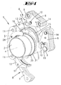
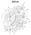
- FIG. 1 is a perspective view of a first embodiment of the pressing tool 1 according to the invention with inserted therein, to be pressed with each other to be compressed tubular workpieces.
- these workpieces are a tube 2 which is inserted into a press fitting 3.
- the workpieces have a common central longitudinal axis x.
- the pressing tool 1 is in the illustrated embodiment is a kind of press chain, as for example from the EP 1455969 B1 is known here.
- the content of this patent is hereby incorporated in full into the disclosure of the present invention, also for the purpose of including features of this patent in claims of the present invention.
- the pressing tool 1 of the embodiment shown consists of four pressing members, which are involved in cooperation in the pressing operation of the workpieces.
- the pressing tool 1 initially two mutually opposite in the circumferential direction pressing members 4, 5, which are mutually displaceable to change a pressing cross section to each other by means of two each formed as an angle lever articulated lever 6 and a hinge lever 7 Kniehebel.
- An articulated lever 6 is connected in each case by means of a knee joint 9 with a toggle lever 7.
- the articulated lever 6 has an outer joint 10 which is connected to the pressing member 4.
- the articulated lever 7 has at its opposite end an outer joint 11 which is connected to the pressing member 5.
- the same reference numerals are used here as in the following for corresponding elements.
- a further pressing member 12, 13 is provided in each case, wherein the pressing members 12,13 also opposite to each other with respect to the pressing cross-section.
- the pressing members 4, 5 are not connected to the pressing members 12, 13 by means of joints, but only held captive on the articulated levers 7 and guided by sliding guides on the pressing members 4, 5. This means that the pressing members regularly enclose the press section or the workpieces to be pressed over the complete circumference before the beginning of the pressing process.
- 6 force introduction elements 14 are provided on articulated levers for introducing force outside the outer joint.
- the pressing members 5, 12 and 13 and the articulated levers 6 each have three parallel spaced plate portions with intermediate parallel ones Fugues on.
- the pressing member 4 and the hinge lever 7 each have two comparable spaced plate areas, which are dimensioned and spaced in such a way that engagement in the joints of the pressing members 5, 12 and 13 and the hinge lever and thus a mutual penetration of the same is made possible.
- the plate portions are integrally connected to each other via pressing jaws 15, 16, 17 and 18, whereby a stable configuration is obtained.
- the illustrated articulated joints between the pressing members 4, 5 and the articulated levers 6, 7 are performed by penetrating through each other in the assembled state terminal bores, inserted through the cylinder pins and are held at their ends by retaining rings.
- the press chain can be opened at the knee joint 9 of the upper toggle lever 8 by a coupling pin 19 is to be displaced into a release position.
- the pressing operation with a corresponding reduction of the pressing cross section is achieved by pressing tool-shaped pressing jaws 20 which act on the pressing tool 1 and are arranged on a hydraulically acting pressing device (not shown) which are part of pressing levers which are arranged in a rotatable manner in a tensioning device.
- the pressing jaws 20 are positively connected by means of the force introduction elements 14 with the articulated levers 6.
- the pressing jaws 20 are acted on the lever-side ends at the rear in such a way that the pressing jaws 20 close like a pincer, which results in a reduction in the distance between the force introduction elements 14 relative to each other.
- the pressing cross section in the region of the pressing jaws 15 to 18 is reduced for pressing.
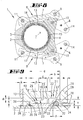
- the pressing jaws 15 to 18 are facing radially inwardly formed the same to be pressed workpieces, show corresponding in a cross section same Verpressgeometrien on. Such a cross section through a pressing jaw is in FIG. 9 shown.
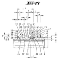
- Each press jaw 15 to 18 has in cross-section as shown in FIG. 9 substantially three in axial alignment of the respective pressing jaw arranged one behind the other, different sections of pressing geometries, so first starting from an axial end of the jaw cross section a first Verpressgeometrie 21, which is formed by a cylinder section shaped bead pressing section 22. This extends approximately over a third the total measured in alignment of the axis x length a of acting on the press fitting 3 total pressing cross section of the pressing jaw 15 to 18.
- a selected axial length a of the press fitting 3 acting total press geometry of about 30 mm in the same Direction measured extension length b of the Wulstpressabites 22 forming cylinder portion of about 10 mm.
- a Kalibrierpressabêt 23 is approximately centrally of the entire axial length a of the effective Verpressgeometrie formed. This is also formed by a cylinder portion, resulting in a cross section according to FIG. 9 as well as in Wulstpressabêt 22 a parallel to the axis x extending Pressbeetzleyungswandung 22 'and 23' results.
- the calibrating press section 23 has a length c measured in the axial direction which corresponds approximately to the length b of the bead pressing section 22.
- the Kalibrierpressabites 23 is provided about one third of the entire length a of the effective pressing cross-section, so on in the illustrated embodiment with a length c of about 10 mm.
- the cylinder section forming the bead pressing section 22 is provided with a larger diameter than the cylinder section for forming the calibrating press section 23.
- the radius excess d between the surfaces 23 'and 22' corresponds to approximately one-fifth of an axial extension length b or c of the pressing sections 22 and 23. Further, this radius projection d corresponds approximately to the material thickness (dimension e) of the fitting 3 to be compressed ,
- the pressing tool 1 or the pressing jaws 15 to 18 are designed in the illustrated embodiment for pressing a 4-inch diameter having a pipe 2 and a correspondingly sized fittings 3.
- 4-inch pipes fittings 3 usually have a wall thickness e of about 2.5 mm.
- a transition section 24 is formed as viewed in the axial direction. This forms a rounded step of the radius transition between the surfaces 22 'and 23'.
- the axial width f of this transition section 24 corresponds approximately to the radius excess d between the surfaces 22 'and 23', is further adjusted according to the material thickness of the fitting to be compressed 3, corresponding to a dimension f of about 2.5 mm in the illustrated embodiment.
- the Radialsupplementarydifferenz g between the pressing surfaces 23 'and 25' of Kalibrierpressabites 23 and cone pressing portion 25 corresponds in this embodiment about the material thickness e of the fitting 2, therefore about 2.5 to 3 mm, while the Radialassidifferenz d between the pressing surfaces 22 'and 23' of Wulstpressabêt 22 and Kalibrierpressabites 23 corresponds to about 0.2 times the unpressed bead height n.
- a second Verpressgeometrie 40 in the form of a cone pressing portion 25 at the Kalibrierpressabêt 23. This is also provided radially inward with a cylindrical surface 25 'aligned concentrically with the axis x.
- the cylinder diameter defining this loading area is reduced in relation to the diameter defining the area 23 'of the calibrating press section 23, for instance by the amount of material thickness (dimension e) of the fitting 3 to be pressed.
- the axial width h of the cone pressing portion 25 also corresponds approximately to the material thickness of the press fitting 3, is so in the illustrated embodiment about 2.5 to 3 mm.
- the conical pressing portion 25 is approximately web-like starting from the surface of the Kalibrierpressabiteses 23 pointing radially inwardly, with an axial dimension that corresponds approximately to the radial projection dimension with respect to the calibration surface 23 '.
- the pressing jaws 15 to 18 extend in cross-section at one end beyond the pressing geometry acting essentially on the press fitting 3 to form a contact bar 27 formed in the region of the end of the escape space 26 facing away from the conical pressing section 25.
- the latter engages radially inwardly beyond that through the cone pressing surface 25 'defined level, to the interaction with a facing, tube plug-side end face 35 of the inserted press fitting.
- a gauge section 28 is fixed on the cheek surface of the bearing web 27 forming the jaw portion and correspondingly on the bead side of the contact web 27, a gauge section 28 is fixed. This is formed integrally against the three-part design of the pressing jaws, forms a semi-circular ring in a floor plan. This is attached to the pressing member 5, wherein the semicircular ends of this gauge section 28 in the prepared position according to FIG. 3 project in sections over the pressing members 12 and 13.
- an inner radius of the annular gauge section 28 is provided, which is adapted to the outer diameter of the pipe to be compressed. Accordingly, the facing end face of the gauge section 28 is at least partially on the facing shell portion of the tube 2, both in the preparation position and in the pressing position, for stabilizing and radially supporting the tube 2.
- the axial distance v of the gauge section 28 to the loading surface of the contact bar 27 and thus in Verpresssituation to the supporting end face 35 of the Fittingwandung is dimensioned in the illustrated embodiment with about three times the thickness K of the gauge section 28.
- the distance v in the illustrated embodiment is about 7.5 mm.
- gauge section 29 is attached. Also this is semicircular shaped in a floor plan with about the pressing members 12 and 13 partially extending free ends. Contrary to gauge section 28, the teach section is 29 thickened, correspondingly has an axial dimension m, which corresponds approximately to three times the thickness k of the gauge section 28, so on, approximately three times the material thickness e of the fitting 3 to be compressed.
- the internal radial dimension of the gauge section 29 is adapted to the external diameter of the fitting 3 to be compressed, so that the gauge section 29, at least in the pressing state, comes into semi-circular contact with the associated wall section of the fitting 3. This also initially a radial support of the fitting 3 and also of the fitting in the pipe 3 pipe 2 is achieved.
- the gauge section 29 forms a conical surface 30.
- the gauge portion 29 is supported on a facing edge 34 of a formed on the fitting 3, circumferential bead 31 from.
- the bead 31 of the press fitting 3 serves to receive an O-ring 32 arranged on the inside, which preferably consists of a rubber-like or rubber-like material.
- the sealing ring 32 is formed circular disk-shaped in cross section.
- the bead 31 covers in cross-section the sealing ring 32, wherein a substantially concentric with the center of the sealing ring cross-section extending vertex portion 33 of the bead 31 viewed in the axial direction of the fitting 3 on both sides merges into flanks 34, which run into the Fittingzylinderwandung.
- the press fitting 3 can be a fitting which can receive a tube 2 for pressing at one end, while the other end the fitting 3 is designed, for example, for welding to a further tube piece or the like.
- the pressing tool 1 according to the invention and the proposed method also feasible on fittings 3, which are formed, for example, sleeve-like on both sides end with pressing section, beyond also press fittings 3 in T-shape, in which a pressing with an inserted tube according to the pressing tool 1 according to the invention at all three pipe receptacles of the fitting can be made, which is justified in particular by the small space of the tool on the pipe insertion side of the fitting 3 opposite side of the bead 31.
- the bead 31 viewed in the axial direction, continues on both sides into fitting cylinder sections, thus towards one side in the direction of an opening serving to receive the tube 2.
- the pipe insertion end of the press fitting 3 delimiting end face of the press fitting 3 is provided with the reference numeral 35.
- the axial distance of the bead 31 to the pipe insertion end face 35 is adapted to the axial extent a of the effective Verpressgeometrie the pressing jaws 15 to 18. Accordingly, the press fitting 3 is for pressing in the press jaws so that the bead 31 rests in the region of Wulstpressabêtes 22 At the same end in the axial direction, axial support between the fitting-side end face 35 and the abutment web 27 takes place, according to which an axial fixation of the fitting 3 to be compressed in the Pressing tool 1 is reached.
- the tube 2 is inserted for compression in the fitting 3, this stop-limited, which is achieved by a mantelinnenwandige stage 36 in the fitting 3.
- the inner diameter of the pipe fitting 3 and the outer diameter of the tube 2 are adapted to each other, so that the tube rests in the non-compressed state tilted and verkantêt in the fitting 3.
- the seal 32 In the between the bead 31 and the tube outer shell obtained annular space is the seal 32, which retains even after inserted tube 2 substantially its circular cross-section.
- the bead 31 has in the unpressed state a radial height n, which corresponds to about 2.5 to 3 times the wall thickness e of the fitting 3, wherein the radial height n is determined by the radial dimension between the shell inner wall of the fitting 3 and the radially outer vertex of the bead 31st
- the cross-sectional diameter of the ring 32 is about 5 mm, resulting in a bead width p measured in the axial extension direction in the unpressed position, which corresponds approximately to three times the material thickness of the fitting, so on illustrated embodiment about 8 mm.
- the measurement points on which this measure is based for defining the width dimension p lie, as shown in FIG FIG. 9 approximately at the reversal point of the circular portion-shaped apex 33 in the flanks 34 of the bead 31st
- the pressing members 4, 5 and 12, 13 abut the press fitting 3 in the region of the cone pressing sections 25, this under frontal axial support by means of the abutment web 27 on the associated end face 35 of the fitting 3.
- the two gauge sections 28 and 29 are in this basic position only in the diametrically opposite end portions of the semicircular Sections approximately centrally of the circumferential extension of the pressing members 12 and 13 at the associated wall portions.
- This more punctiform system is denoted by the reference numerals 37 and 38 in the illustrations 4 and 5, wherein with 37 the contact zones of the gauge section 28 on the tube 2 and 38 the contact zones of the gauge section 29 on the fitting 3 rearward the flank 34 of the bead 31st are designated.
- the sheet surface of the respective gauge section 28 or 29 facing towards the workpiece increases towards the center of the gauge section so that the maximum radial distance between the gauge section and associated workpiece is achieved opposite to the force introduction elements 14 ,
- the contraction of the press jaws achieves both a deformation of the fitting 3 and the tube 2 in the region of the conical pressing section 25 and also a deformation in the region of the bead pressing section 22.
- the pressurization of the bead 31 from radially outward by the cylindrical surface 22 'of the bead pressing section 22 causes an axial broadening of the bead 31, resulting from a flattening of the apex 33, and the legs 34, resulting in a compressed Wulstbreitenfriendly r, which is about the 1st , 5 times the original Wulstbreiten beaus p corresponds and is further adapted to the axial extension length b of the bead pressing section 22.
- the annular space receiving the sealing ring 32 is also radially reduced, which results in a deformation of the O-sealing ring 32 in an elongate cross-section considered in the axial direction has, along with an increase in the effective sealing surfaces.
- the provided with an axial distance t to Wulstpressabêt 22 cone pressing portion 25 causes a deformation of the pipe 2 and fitting 3 such that a trigger fuse adjusts.
- This is indicated by an in section as shown in FIG. 12 achieved adjusting V-shaped course of the wall sections.
- the cone press section 25 raises a radially widening cone section both on the pipe side and on the fitting side, which merges in the region of the calibrating press section 23 into a cylindrical section which is axially shortened compared to the calibrating press section 23.
- the Kalibrierpressabêt 23 serves the formation of this cylindrical portion, not by Pressbeetzschung, but rather by forming a sleeve, which counteracts a deformation deviating from the cylindrical shape.
- the axial distance between the axial center region of the compressed bead 31 and the reversal zone of the overall V-shaped raised shell wall sections of the fitting 3 corresponds to the above-described axial distance t between bead pressing section 22 and cone pressing section 25.
- the measured from this V-vertex of the raised shell wall sections axial distance u to the end face 35 corresponds in the illustrated embodiment about 0.4 times the axial dimension t, so on about three times the material thickness e of the fitting third
- the illustrated and described embodiment shows a pressing tool 1 in the form of a press chain.
- the forceps acting acting with two half-shell-shaped pressing jaws which have the above-described pressing geometry, are provided.
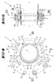
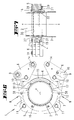
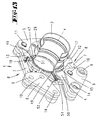
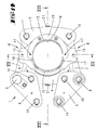
- FIGS. 13 to 20 show a second embodiment of the pressing tool 1 according to the invention, which has the same as the first embodiment four pressing members, which are involved in cooperation in the pressing operation of the workpieces, so on in the manner of a press chain.
- the pressing tool 1 of the second embodiment is designed for pressing fittings 3 and smaller diameter pipes 2, for example, with a diameter of 1.5 inches.
- the following constructive solutions are also transferable to pressing tools 1 for pressing fittings 3 and pipes 2 of increased diameter, as described for example with reference to the first embodiment.
- the pressing jaws 15 to 18 of the pressing tool 1 according to the second embodiment are compared to those of the first embodiment extended over the axial dimension a of the overall press geometry. This is exemplary in FIG. 17 described with reference to the pressing jaw 18, wherein, as in the first embodiment, the Verpressgeometrien described in this regard are formed on all pressing jaws.
- the pressing jaw 18 of the second embodiment is viewed laterally flanked by the gauge sections 28 and 29.
- the second Verpressgeometrie 40 immediately adjacent to the gauge section 28, which second Verpressgeometrie in the axial direction of the first Verpressgeometrie 21 connects.
- a pressing jaw portion 45 is left. This has an axial length j, which corresponds approximately to the axial length c of the Kalibrierpressabiteses 23.
- the extended press jaw section 45 is partially radially enlarged, so on about the radius excess d between the pressing surfaces 23 'and 22' of the Kalibrierpressabiteses 23 and the bead pressing section 22, which radius excess d in this embodiment about 1.5 times the material thickness e of the fitting to be compressed 3 corresponds. Furthermore, the radial excess d corresponds approximately to 0.5 times the bead height n measured in the radial direction in the unpressed state.
- the pressing jaw section 45 adjoining the bead pressing section 22 in the direction of the gauge section 29 is not integrated into the pressing geometry; acts accordingly in the course of the pressing process not forming on the fitting 3 a.
- the radial expansion in the region of the pressing jaw section 45 is not provided over the entire circumferential length of this section 45, but rather with respect to the entire pressing tool 1 only in two diametrically opposite areas, namely concretely in the middle of the circumferential extensions of the pressing members 12 and 13 and the pressing jaws 17 and 18, so on in the form of axially extending from the gauge section 29, bore-like pockets 46. These are to their opening side covered by the flanking gauge section 29, which is also in this embodiment as shown in FIG FIG. 14 in a plan is designed approximately semicircular.
- the gauge section 29 faces the press jaw section 45, further associated with the pockets 46, abutment elements 47. These are provided with an axial depth which corresponds approximately to 0.8 times the length j measured in the same direction of the press jaw section 45.
- the two diametrically opposed abutment elements 47 are initially formed like a pin, with a content in the gauge section 29 sockets pedestal 48.
- This base 48 carries this diameter enlarged relative to the cap portion facing the free end has a circumferential, adapted to the bead flanks 34 cone surface 30.
- the arrangement and configuration of the contact elements 47 is selected so that in a prepared for pressing position as shown in FIG FIG. 17 the conical surface 30 of the respective contact element 47 is supported against the bead flank 34 facing away from the free fitting end and thus assumes the function of the conical surface 30 of the gauge section 29 according to the first embodiment.
- the respective pressing jaw section 45 is radially selected outside the pockets 46 so that its radially inner surface coincides with the pressing surface 22 'of the bead pressing section 22. This applies to the pressing jaws 15 and 16 via their respective entire peripheral portion (see. FIG. 18 ).
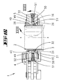
- the pressing members 4 and 5 in the region of their pressing jaws 15 and 16 each have a radially biased pressing portion 49 in the form of a pin-like, radially inwardly spring-loaded element.
- This pressing portion 49 is positioned in the region of the transition portion 24 between the Kalibrierpressabêt 23 and the bead pressing portion 22 viewed in the axial direction.
- a radial bore 50 is provided, which are covered radially outwardly by caps 51, for example, screw caps. After radially inward, the bore 50 tapers and runs open in the press room.
- a compression spring 52 which acts on the pressing portion 49 radially inward.
- the pressing section 49 has a plate section 53 enlarged in diameter as compared with the section projecting freely radially inwards. This is diameter-adjusted in the bore 50 a.
- the compression spring 52 acts, which plate 52 also acts stop limiting.
- Each pressing section 49 is formed as a circular cylinder with a conically shaped tip 54, wherein the cone angle is adapted to the angle of a facing bead flank 34.
- the diameter of each pressing section 49 corresponds in the illustrated embodiment about a 1.2 times the axial length c of Calibration press section 23.
- the fitting 3 together with the tube 2 is used according to the first embodiment in the pressing tool 1, after which centering of the pressing tool 1 to the fitting via the two teaching side abutment elements 47 and the two offset by 90 ° in the circumferential direction biased pressing sections 49 3, in particular to the bead 31 is reached. Due to the radially inward spring-loaded pressing sections 49, the bead 31 and the opposite bead flank 34 are pressed against the conical surfaces 30 of the abutment elements 47 via the abutment on the associated bead flank 34, which results in self-centering.
- deformation of the fitting 3 and tube 2 in the region of the cone pressing section 25 as well as deformation in the region of the bead pressing section 22 are achieved in the course of the compression by the contraction of the pressing jaws.
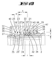
- the pressurization of the bead 31 from radially outward by the cylindrical surface 22 'of the bead pressing section 22 causes an axial widening of the bead 31, resulting from a flattening of the apex 33, and the legs 34, resulting in a compressed Wulstumblen beau r (see. FIG. 19 ), which is about 1.3 times the original bead width dimension p.
- the annular space receiving the sealing ring 32 is radially reduced, which results in a deformation of the O-sealing ring 32 in an elongate cross-section considered in the axial direction, accompanied by an enlargement of the effective sealing surface.
- the deformation of tube 2 and fitting 3 in the region of the cone pressing portion 25 is designed according to the deformation according to the first embodiment.
- the fixed in the gauge section 29, facing in the direction of the bead 31 contact elements 47 cause at least partially deformation of the bead 31 in the course of the pressing process only in the direction of the free insertion end of the fitting 3 according to the corresponding support of the bead 31 on the conical surface 30 of the Gauge section 29 in the first embodiment.
- the spring-loaded pressing portions 49 dive in the course of the pressing process while overcoming the rearwardly acting on her spring force radially outward into the bore 50 a. This radial displacement of the pressing sections 49 occurs before pressing the directly cooperating with these pressing portions 49 area to avoid damage to the fitting 3 and / or the tube 2.
- the spring force of the respective compression spring 52 is in this case counted so that the tip 54 of each pressing portion 49 is always in contact with the facing edge 34 of the bead 31, but further by the axial broadening of the bead 31 in the course of compression also on the bead flank 34, a radial component on the associated pressing portion 49 acts radially outward.
Landscapes
- Engineering & Computer Science (AREA)
- Mechanical Engineering (AREA)
- General Engineering & Computer Science (AREA)
- Automatic Assembly (AREA)
- Shaping Metal By Deep-Drawing, Or The Like (AREA)
- Extrusion Moulding Of Plastics Or The Like (AREA)
- Non-Disconnectible Joints And Screw-Threaded Joints (AREA)
- Mutual Connection Of Rods And Tubes (AREA)
- Tyre Moulding (AREA)
Claims (15)
- Procédé de compression d'un raccord de compression (3) avec un tube (2) inséré dans le raccord de compression (3) au moyen d'un outil de compression (1), le raccord de compression (3) présentant un bourrelet périphérique (31), dans lequel un joint torique d'étanchéité (32) est inséré, le tube (2) se terminant à l'intérieur du raccord de compression (3) et une première compression étant réalisée à l'intérieur du bourrelet (31), une compression supplémentaire étant de plus réalisée du côté du tube inséré sur l'extrémité du raccord de compression à distance du bourrelet, compression qui, à la suite d'un segment presseur conique sur l'outil de presse, conduit à une conicité du raccord de compression (3) et du tube (2), s'étendant dans la même direction, et le bourrelet (31) au cours de la compression étant étalé axialement et uniformément des deux côtés, par une sollicitation radiale depuis l'extérieur et partant d'un sommet du bourrelet, de surcroît la compression supplémentaire n'étant réalisée que, du côté du tube inséré, sur l'extrémité du raccord de compression pour empêcher la séparation de la combinaison comprimée du raccord de compression (3) et du tube (2), sans une sollicitation de pression du segment de raccord s'étendant derrière le bourrelet et pour l'orientation axiale au niveau de l'extrémité de l'outil de presse (1) tournée vers le segment presseur conique (25), un support d'appui (27) est mis pour s'appuyer sur une face frontale (35) du raccord de compression.
- Procédé selon la revendication 1, caractérisé en ce que le bourrelet (31) est sollicité avec un segment cylindrique sur l'outil de presse (1).
- Procédé selon l'une des revendications 1 ou 2, caractérisé en ce que la compression supplémentaire, du côté du tube inséré, est réalisée dans la zone d'une distance (t) correspondant à au moins 1,5 fois ou plus la dimension de hauteur (n) du bourrelet (31) non comprimé, depuis le bourrelet (31) vers l'extrémité du raccord de compression du côté du tube inséré, dans lequel de préférence, au niveau de l'extrémité du bourrelet (31) tournée vers l'extrémité du raccord de compression (3) du côté du tube inséré, une stabilisation de l'outil de presse (1) par rapport à l'axe longitudinal du tube (x) est réalisée au moyen d'un segment de calibre (29) sur l'outil de presse (1) et/ou de façon particulièrement préférée, une compression d'étalonnage est réalisée entre la compression de bourrelet et la compression du côté du tube inséré.
- Procédé selon l'une des revendications précédentes, caractérisé en ce que l'orientation axiale de l'outil de presse (1) est réalisée à l'aide d'un support d'appui (27) s'appuyant sur une face frontale du raccord de compression (3), dans lequel, de préférence, il est procédé à une saisie du tube (2), à la façon d'un calibre, du côté du support d'appui (27) faisant dos au bourrelet et/ou de façon particulièrement préférée, du côté du tube inséré du bourrelet (31), il est prévu un segment presseur (49) précontraint radialement qui dévie radialement au cours de la compression et en atteignant la force de précontrainte afin de s'intégrer dans le reste de la géométrie de compression.
- Procédé selon la revendication 4, caractérisé en ce que, dans le cas du segment presseur précontraint, la précontrainte est agencée de manière qu'il ne se produise pas de déformation plastique du raccord avant la déviation radiale.
- Outil de presse (1) pour comprimer des raccords de compression (3) sur des tubes (2), l'outil de presse (1) présentant au moins deux mâchoires de presse (15, 16, 17, 18) avec une première géométrie de compression (21) pour former un segment presseur (22) de bourrelet et une seconde géométrie de compression espacée axialement (40) de la première pour former un segment presseur conique (25), la première géométrie de compression (21) dotée d'un plus grand diamètre présentant un segment cylindrique de manière à laisser de la place au bourrelet (31) dans une direction pour un étalement axial, de plus la seconde géométrie de compression n'étant formée que d'un côté de la première géométrie de compression et servant à empêcher la séparation de la combinaison comprimée du raccord de compression (3) et du tube (2), et entre le segment presseur (22) de bourrelet et le segment presseur conique (25), un segment presseur d'étalonnage étant formé, qui est prévu, compte tenu d'une distance radiale entre le segment presseur (22) de bourrelet et le segment presseur conique (25), dans lequel, de surcroît, le segment presseur conique (25) par rapport au segment presseur (22) de bourrelet laisse un espace intérieur radial réduit et le segment presseur d'étalonnage (23) laisse un espace intérieur radial, dont le diamètre se trouve dimensionnellement entre celui du segment presseur conique (25) et celui du segment presseur de bourrelet (22), et au niveau de l'extrémité de l'outil de presse (1) tournée vers le segment presseur conique (25), il est prévu un support d'appui (27) afin de s'appuyer sur une face frontale du raccord de compression.
- Outil de presse selon la revendication 6, caractérisé en ce que, dans la géométrie de compression, il est prévu un segment presseur radialement précontraint (49) qui dévie radialement au cours de la compression et en atteignant la force de précontrainte afin de s'intégrer dans le reste de la géométrie de compression.
- Outil de presse selon l'une des revendications 6 ou 7, caractérisé en ce qu'un segment de calibre (29) est formé sur l'outil de presse (1), dans lequel, de préférence, au niveau du segment de calibre (29), il est prévu des éléments d'appui (47) orientés dans la direction de la première géométrie.
- Outil de presse selon l'une des revendications 6 à 8, caractérisé en ce que le segment presseur d'étalonnage (23) présente un segment cylindrique et/ou, de préférence, la dimension radiale (g) de la surface d'appui (23') du segment presseur d'étalonnage (23) est en retrait de 1,25 mm ou plus par rapport à la dimension radiale de la surface d'appui (25') du segment presseur conique (25) et/ou de manière particulièrement préférée, la dimension radiale (d) de la surface cylindrique (22') du segment presseur de bourrelet (22) est augmentée de 0,625 mm à 5,625 mm par rapport à la dimension radiale de la surface d'appui (23') du segment presseur d'étalonnage(23).
- Outil de presse selon la revendication 9, caractérisé en ce qu'un segment de transition (24) est formé entre le segment presseur de bourrelet (22) et le segment presseur d'étalonnage (23), correspondant au moins à la largeur axiale (h) du segment presseur conique (25) et/ou, de préférence, un segment de transition (24) est formé entre le segment presseur de bourrelet (22) et le segment presseur d'étalonnage (23), correspondant à moins de la largeur axiale (h) du segment presseur conique (25), dans lequel, de manière particulièrement préférée, le segment presseur (49) précontraint radialement est serré à l'état comprimé dans le segment de transition (24) entre le segment presseur de bourrelet (22) et le segment presseur d'étalonnage(23).
- Outil de presse selon l'une des revendications 6 à 10, caractérisé en ce que le segment cylindrique du segment presseur de bourrelet (22) présente une longueur axiale (b) qui correspond à un multiple de la longueur axiale (h) du segment presseur conique (25).
- Outil de presse selon l'une des revendications 9 ou 11, caractérisé en ce que le segment cylindrique du segment presseur d'étalonnage (23) présente une longueur axiale (c) qui correspond à un multiple de la longueur axiale (h) du segment presseur conique (25).
- Outil de presse selon l'une des revendications 6 à 12, caractérisé en ce que le segment presseur conique (25) présente une longueur axiale (h) qui correspond à une longueur de 1,25 à 12,5 mm.
- Outil de presse selon l'une des revendications 6 à 13, caractérisé en ce que, sur le côté du support d'appui (27) faisant dos au segment presseur de bourrelet, il est prévu un second segment de calibre (28) et/ou, de manière particulièrement préférée, le premier segment de calibre (29) prévu du côté du premier segment de compression est formé en demi-cylindre et/ou de manière tout particulièrement préférée, le second segment de calibre (28) est formé en demi-cylindre.
- Outil de presse selon l'une des revendications 8 à 14, caractérisé en ce que le premier segment de calibre (29) présente une étendue longitudinale axiale qui correspond à 3,75 mm ou plus, dans lequel, de préférence, le premier segment de calibre (29) présente une longueur axiale (m) qui correspond à un multiple de la longueur axiale (h) du segment presseur conique (25), et/ou, de manière particulièrement préférée, la dimension radiale (g) de la surface d'appui (23') du segment presseur d'étalonnage (23) est en retrait de 1,25 mm ou plus par rapport à la dimension radiale de la surface d'appui (25') du segment presseur conique (25), et/ou, de manière tout particulièrement préférée, la dimension radiale (d) de la surface cylindrique (22') du segment presseur de bourrelet (22) est augmentée de 0,625 mm à 5,625 mm par rapport à la dimension radiale de la surface d'appui (23') du segment presseur d'étalonnage (23).
Priority Applications (3)
| Application Number | Priority Date | Filing Date | Title |
|---|---|---|---|
| PL11181969T PL2400199T3 (pl) | 2006-08-22 | 2007-08-22 | Sposób zaprasowywania, układ do zaprasowywania i narzędzie zaprasowujące |
| EP20110181969 EP2400199B1 (fr) | 2006-08-22 | 2007-08-22 | Procédé de compression d'un raccord pressfit et outil de compression associé |
| PL07802803T PL2057397T3 (pl) | 2006-08-22 | 2007-08-22 | Sposób zaprasowywania złącza rurowego oraz narzędzie do zaprasowywania złączy rurowych |
Applications Claiming Priority (3)
| Application Number | Priority Date | Filing Date | Title |
|---|---|---|---|
| DE102006039364 | 2006-08-22 | ||
| DE200610050427 DE102006050427A1 (de) | 2006-08-22 | 2006-10-20 | Verfahren zum Verpressen eines Pressfittings sowie Presswerkzeug hierzu |
| PCT/EP2007/058731 WO2008023035A1 (fr) | 2006-08-22 | 2007-08-22 | procédé de compression d'un raccord de compression et outil de presse associé |
Related Child Applications (2)
| Application Number | Title | Priority Date | Filing Date |
|---|---|---|---|
| EP20110181969 Division EP2400199B1 (fr) | 2006-08-22 | 2007-08-22 | Procédé de compression d'un raccord pressfit et outil de compression associé |
| EP11181969.4 Division-Into | 2011-09-20 |
Publications (2)
| Publication Number | Publication Date |
|---|---|
| EP2057397A1 EP2057397A1 (fr) | 2009-05-13 |
| EP2057397B1 true EP2057397B1 (fr) | 2013-04-24 |
Family
ID=38812058
Family Applications (2)
| Application Number | Title | Priority Date | Filing Date |
|---|---|---|---|
| EP07802803.2A Active EP2057397B1 (fr) | 2006-08-22 | 2007-08-22 | Procédé de compression d'un raccord de compression et outil de presse associé |
| EP20110181969 Not-in-force EP2400199B1 (fr) | 2006-08-22 | 2007-08-22 | Procédé de compression d'un raccord pressfit et outil de compression associé |
Family Applications After (1)
| Application Number | Title | Priority Date | Filing Date |
|---|---|---|---|
| EP20110181969 Not-in-force EP2400199B1 (fr) | 2006-08-22 | 2007-08-22 | Procédé de compression d'un raccord pressfit et outil de compression associé |
Country Status (10)
| Country | Link |
|---|---|
| US (2) | US8490261B2 (fr) |
| EP (2) | EP2057397B1 (fr) |
| KR (1) | KR101468440B1 (fr) |
| CN (2) | CN102962810B (fr) |
| CA (1) | CA2658938C (fr) |
| DE (1) | DE102006050427A1 (fr) |
| ES (2) | ES2411690T3 (fr) |
| PL (2) | PL2057397T3 (fr) |
| RU (1) | RU2434176C2 (fr) |
| WO (1) | WO2008023035A1 (fr) |
Families Citing this family (38)
| Publication number | Priority date | Publication date | Assignee | Title |
|---|---|---|---|---|
| DE102006050427A1 (de) * | 2006-08-22 | 2008-02-28 | Gustav Klauke Gmbh | Verfahren zum Verpressen eines Pressfittings sowie Presswerkzeug hierzu |
| DE102008005854A1 (de) * | 2008-01-16 | 2009-07-23 | REMS-WERK Christian Föll und Söhne GmbH & Co KG | Pressring sowie Zange zur Verwendung mit einem solchen Pressring |
| GB2460710A (en) * | 2008-02-29 | 2009-12-16 | Todays Tools Ltd | A tool for removal of compression fittings from pipes |
| EP2196713B1 (fr) | 2008-12-12 | 2012-06-13 | Conex Universal Limited | Dispositif, procédé et kit de pièces pour former un raccord de sertissage avec un tuyau |
| DE102009007303B4 (de) | 2009-02-03 | 2023-05-04 | Viega Technology Gmbh & Co. Kg | Fitting für dickwandige Rohre |
| US20100253066A1 (en) * | 2009-04-02 | 2010-10-07 | Victaulic Company | Crimp-Type Coupling, Crimping Tool and Method of Crimping |
| DE202009009456U1 (de) * | 2009-07-15 | 2010-11-25 | Novopress Gmbh Pressen Und Presswerkzeuge & Co. Kommanditgesellschaft | Presswerkzeug zum Verbinden von insbesondere rohrförmigen Werkstücken |
| DE102009057726A1 (de) * | 2009-12-10 | 2011-06-16 | Uniflex-Hydraulik Gmbh | Radialpresse |
| US8245789B2 (en) * | 2010-06-23 | 2012-08-21 | Halliburton Energy Service, Inc. | Apparatus and method for fluidically coupling tubular sections and tubular system formed thereby |
| KR101034454B1 (ko) * | 2010-07-29 | 2011-05-17 | 김광찬 | 파이프 압착 체결장치 |
| DE102011052852A1 (de) | 2011-08-19 | 2013-02-21 | Gustav Klauke Gmbh | Pressvorrichtung |
| US8590352B2 (en) * | 2011-11-23 | 2013-11-26 | Emerson Electric Co. | Integral inspection gauge for manual crimping tool |
| DE102011088388A1 (de) * | 2011-12-13 | 2013-06-13 | Novopress Gmbh Pressen Und Presswerkzeuge & Co. Kg | Verfahren zur Herstellung einer Rohrverbindung mittels Pressfitting sowie Presswerkzeug |
| RU2482373C1 (ru) * | 2012-05-12 | 2013-05-20 | Общество С Ограниченной Ответственностью "Водопад Групп" | Соединительный комплект для труб, способ соединения трубы с фитингом, гайка и инструмент (варианты) |
| DE102012105655A1 (de) * | 2012-06-28 | 2014-01-02 | Viega Gmbh & Co. Kg | Pressbacke und Verfahren zum Herstellen einer unlösbaren Rohrverbindung und System aus einer Pressbacke und einem Fitting |
| CN102805676B (zh) * | 2012-08-14 | 2015-06-17 | 杭州启明医疗器械有限公司 | 人造瓣膜置换装置的压缩装置 |
| DE202013007496U1 (de) * | 2013-08-21 | 2014-11-28 | Novopress Gmbh Pressen Und Presswerkzeuge & Co. Kg | Pressschlinge zum Verbinden von insbesondere rohrförmigen Werkstücken |
| US9808893B2 (en) | 2013-12-19 | 2017-11-07 | Walhonde Tools Inc. | Apparatus for aligning sections of pipe |
| EP3015751B2 (fr) | 2014-10-31 | 2024-05-01 | Conex IPR Limited | Raccord destiné à un branchement à un élément tubulaire, raccord de tube et procédé pour relier un raccord à un élément tubulaire |
| DE102015103228B4 (de) * | 2015-03-05 | 2018-03-22 | Viega Technology Gmbh & Co. Kg | Presshülse, Pressfitting und Verwendung des Pressfittings oder der Presshülse |
| US10312653B2 (en) | 2015-05-06 | 2019-06-04 | Milwaukee Electric Tool Corporation | Hydraulic tool |
| CN104985063B (zh) * | 2015-08-08 | 2017-02-15 | 陈瑞峰 | 一种卡压环模 |
| IT201600093853A1 (it) * | 2016-09-19 | 2018-03-19 | Raccorderie Metalliche Spa | Sistema universale di giunzione indissolubile per tubi e giunto compreso in detto sistema |
| EP3338908B1 (fr) * | 2016-12-21 | 2019-11-20 | Von Arx AG | Anneau de presse avec trous allongés |
| CN106583569B (zh) * | 2017-01-23 | 2018-02-23 | 湖南金峰金属构件有限公司 | 一种多单元组合冷挤压机 |
| CN107685111A (zh) * | 2017-10-20 | 2018-02-13 | 台州巨力工具有限公司 | 一种薄壁金属管件压模 |
| CN107803649B (zh) * | 2017-11-30 | 2023-11-24 | 成都瑞戈科技有限公司 | 一种防尘罩小卡圈自动装配机 |
| CN107838658B (zh) * | 2017-11-30 | 2023-11-24 | 成都瑞戈科技有限公司 | 防尘罩小卡圈自动装配系统 |
| CN108620498B (zh) * | 2018-04-28 | 2020-11-03 | 浙江康帕斯流体输送技术有限公司 | 一种卡压式管件的环压工具 |
| RU184420U9 (ru) * | 2018-07-27 | 2018-11-21 | федеральное государственное бюджетное образовательное учреждение высшего образования "Донской государственный технический университет" (ДГТУ) | Неразъемное трубное соединение упрощенного монтажа |
| US12244127B2 (en) * | 2020-08-27 | 2025-03-04 | Te Connectivity Solutions Gmbh | Cutting arm for a cable preparation machine |
| US11090708B1 (en) | 2020-10-02 | 2021-08-17 | Trinity Bay Equipment Holdings, LLC | Swage machine hinge systems and methods |
| US11185911B1 (en) * | 2021-03-05 | 2021-11-30 | Trinity Bay Equipment Holdings, LLC | Swage machine modular grab adapter systems and methods |
| CN112873125A (zh) * | 2021-03-12 | 2021-06-01 | 安徽昌宁新材料有限公司 | 一种用于管件配套的挤压钳 |
| PL4086018T3 (pl) * | 2021-05-04 | 2024-09-09 | Viega Technology Gmbh & Co. Kg | Układ do łączenia rur sztywnych i łączenia rur elastycznych |
| CN113695471B (zh) * | 2021-08-27 | 2023-05-30 | 深圳市鸿源文具有限公司 | 一种工字轮装配机及一种成形模具 |
| US12611754B2 (en) | 2022-07-29 | 2026-04-28 | Black & Decker Inc. | Crimping and/or pinching accessory for power tool |
| IT202300015468A1 (it) * | 2023-07-24 | 2025-01-24 | Psp S R L | Raccordo a pressare per tubi corrugati e lisci e utensile predisposto per tale pressatura |
Citations (4)
| Publication number | Priority date | Publication date | Assignee | Title |
|---|---|---|---|---|
| US4850621A (en) * | 1988-03-22 | 1989-07-25 | Usui Kokusai Sangyo Kabushiki Kaisha | Structure having interconnected metal tubes |
| US5484174A (en) * | 1988-07-13 | 1996-01-16 | Mie Horo Co., Ltd. | Pipe coupling and method of joining materials |
| WO2000012925A1 (fr) * | 1998-08-26 | 2000-03-09 | Mapress Gmbh & Co. Kg | Raccord tubulaire |
| US6581983B1 (en) * | 2000-02-21 | 2003-06-24 | Franz Viegener Ii Gmbh & Co. Kg | Fitting or mounting for producing a press joint with an inserted tube end |
Family Cites Families (32)
| Publication number | Priority date | Publication date | Assignee | Title |
|---|---|---|---|---|
| US3244441A (en) * | 1961-12-28 | 1966-04-05 | Mueller Co | Crimped tube joint |
| JPS5588939A (en) * | 1978-12-27 | 1980-07-05 | Nippon Benkan Kogyo Kk | Joint connection method |
| GB2205373B (en) * | 1987-05-23 | 1991-04-24 | Mie Horo Co Ltd | Method of making piping joints and joining tool |
| EP0361630B1 (fr) * | 1988-09-30 | 1992-06-10 | MANNESMANN Aktiengesellschaft | Méthode et dispositif et raccord à comprenion pour fabriquer une jonction inséparable, hermétique pour tuyaux |
| US5168618A (en) * | 1988-09-30 | 1992-12-08 | Mannesamnn Ag | Method of forming a crimped sleeve to tube joint |
| JPH04248090A (ja) * | 1991-01-23 | 1992-09-03 | Riken Corp | シ−ルリング検出機能付きプレス配管装置 |
| DE9103264U1 (de) * | 1991-03-18 | 1991-06-20 | Hewing GmbH, 4434 Ochtrup | Preßzange für das Verpressen von Rohrverbindungen |
| DE9216369U1 (de) * | 1992-12-02 | 1993-02-04 | Novopress GmbH Pressen und Presswerkzeuge & Co KG, 4040 Neuss | Preßwerkzeug |
| DE29521410U1 (de) * | 1995-11-04 | 1997-04-24 | Novopress GmbH Pressen und Presswerkzeuge & Co KG, 41460 Neuss | Kombination aus Preßfitting, Rohr und Preßgerät sowie Preßgerät dafür |
| EP0858568B1 (fr) * | 1995-11-04 | 2001-12-12 | Novo-Press GmbH Pressen und Presswerkzeuge & Co. Kg. | Procede de raccordement d'un tuyau avec un raccord emmanche a la presse, combinaison de raccord emmanche a la presse, de tuyau et de presse |
| DE19722935C1 (de) * | 1997-05-27 | 1998-07-09 | Mannesmann Ag | Preßfitting zur Herstellung einer unlösbaren Verbindung von Rohren |
| DE19725557C1 (de) | 1997-06-12 | 1999-02-04 | Mannesmann Ag | Rohrpreßverbindung |
| DE29721760U1 (de) * | 1997-12-10 | 1998-01-29 | Franz Viegener II GmbH & Co. KG, 57439 Attendorn | Unlösbare Preßverbindung zwischen einem Fitting und einem Metallrohrende |
| DE29721759U1 (de) * | 1997-12-10 | 1998-04-09 | Franz Viegener II GmbH & Co. KG, 57439 Attendorn | Preßwerkzeug zum unlösbaren Verbinden eines Fittings und eines eingeführten Metallrohrendes |
| JP4248090B2 (ja) | 1998-08-24 | 2009-04-02 | 有限会社末永製作所 | 泥漿処理装置及び泥漿処理装置に用いられる処理搬送ポンプ |
| DE10144100C1 (de) * | 2001-09-04 | 2003-02-13 | Mapress Gmbh & Co Kg | Verfahren und Vorrichtung zur Herstellung einer Rohrpressverbindung |
| US7143626B2 (en) * | 2001-10-24 | 2006-12-05 | Victaulic Company | Crimping jaw having energy efficient crimping dies |
| AU2002364392A1 (en) * | 2001-12-08 | 2003-06-23 | Gustav Klauke Gmbh | Pressing device |
| DE10303296B3 (de) * | 2003-01-28 | 2004-07-29 | Kaimer Gmbh & Co. Holding Kg | Pressfitting |
| JP4447261B2 (ja) * | 2003-07-18 | 2010-04-07 | 株式会社キッツ | プレス式管継手の接合方法 |
| DE20318618U1 (de) * | 2003-12-02 | 2005-04-14 | Gustav Klauke Gmbh | Verpressbackenpaar für ein Presswerkzeug |
| US7818856B2 (en) * | 2004-01-06 | 2010-10-26 | Raczuk Richard C | Method and tool for mating a hose and connector |
| DE202004002138U1 (de) * | 2004-02-12 | 2005-06-30 | Viega Gmbh & Co. Kg | Pressverbindung |
| CA2580289C (fr) * | 2004-09-17 | 2013-07-09 | Lokring Technology Corporation | Ensemble outil d'installation |
| US7823271B2 (en) * | 2005-02-11 | 2010-11-02 | John Mezzalingua Associates, Inc. | Connector compression tool |
| WO2007010339A2 (fr) * | 2005-07-19 | 2007-01-25 | Pi.Effe.Ci. S.R.L. | Outil conçu pour le raccordement de tubes au moyen de manchons de raccordement |
| DE102006050427A1 (de) * | 2006-08-22 | 2008-02-28 | Gustav Klauke Gmbh | Verfahren zum Verpressen eines Pressfittings sowie Presswerkzeug hierzu |
| US20080307934A1 (en) * | 2007-06-14 | 2008-12-18 | Rgb Systems, Inc. | Multi-purpose cable crimping tool |
| US7987690B2 (en) * | 2008-01-04 | 2011-08-02 | Cerro Flow Products Llc | Fluid conduits with integral end fittings and associated methods of manufacture and use |
| US20100253066A1 (en) * | 2009-04-02 | 2010-10-07 | Victaulic Company | Crimp-Type Coupling, Crimping Tool and Method of Crimping |
| DE202009009456U1 (de) * | 2009-07-15 | 2010-11-25 | Novopress Gmbh Pressen Und Presswerkzeuge & Co. Kommanditgesellschaft | Presswerkzeug zum Verbinden von insbesondere rohrförmigen Werkstücken |
| DE102011052852A1 (de) * | 2011-08-19 | 2013-02-21 | Gustav Klauke Gmbh | Pressvorrichtung |
-
2006
- 2006-10-20 DE DE200610050427 patent/DE102006050427A1/de not_active Withdrawn
-
2007
- 2007-08-22 CN CN201210395714.8A patent/CN102962810B/zh active Active
- 2007-08-22 EP EP07802803.2A patent/EP2057397B1/fr active Active
- 2007-08-22 US US12/377,520 patent/US8490261B2/en active Active
- 2007-08-22 EP EP20110181969 patent/EP2400199B1/fr not_active Not-in-force
- 2007-08-22 PL PL07802803T patent/PL2057397T3/pl unknown
- 2007-08-22 CN CN2007800302851A patent/CN101501383B/zh not_active Expired - Fee Related
- 2007-08-22 PL PL11181969T patent/PL2400199T3/pl unknown
- 2007-08-22 KR KR1020097005647A patent/KR101468440B1/ko active Active
- 2007-08-22 ES ES07802803T patent/ES2411690T3/es active Active
- 2007-08-22 ES ES11181969.4T patent/ES2524165T3/es active Active
- 2007-08-22 WO PCT/EP2007/058731 patent/WO2008023035A1/fr not_active Ceased
- 2007-08-22 CA CA2658938A patent/CA2658938C/fr not_active Expired - Fee Related
- 2007-08-22 RU RU2009110213A patent/RU2434176C2/ru not_active IP Right Cessation
-
2013
- 2013-06-17 US US13/919,397 patent/US9015916B2/en active Active
Patent Citations (4)
| Publication number | Priority date | Publication date | Assignee | Title |
|---|---|---|---|---|
| US4850621A (en) * | 1988-03-22 | 1989-07-25 | Usui Kokusai Sangyo Kabushiki Kaisha | Structure having interconnected metal tubes |
| US5484174A (en) * | 1988-07-13 | 1996-01-16 | Mie Horo Co., Ltd. | Pipe coupling and method of joining materials |
| WO2000012925A1 (fr) * | 1998-08-26 | 2000-03-09 | Mapress Gmbh & Co. Kg | Raccord tubulaire |
| US6581983B1 (en) * | 2000-02-21 | 2003-06-24 | Franz Viegener Ii Gmbh & Co. Kg | Fitting or mounting for producing a press joint with an inserted tube end |
Also Published As
| Publication number | Publication date |
|---|---|
| DE102006050427A1 (de) | 2008-02-28 |
| CN101501383A (zh) | 2009-08-05 |
| RU2434176C2 (ru) | 2011-11-20 |
| KR20090046946A (ko) | 2009-05-11 |
| ES2411690T3 (es) | 2013-07-08 |
| CN102962810B (zh) | 2016-06-29 |
| EP2400199B1 (fr) | 2014-11-05 |
| RU2009110213A (ru) | 2010-09-27 |
| CN102962810A (zh) | 2013-03-13 |
| US20130277958A1 (en) | 2013-10-24 |
| CA2658938C (fr) | 2015-09-29 |
| CN101501383B (zh) | 2013-08-21 |
| US8490261B2 (en) | 2013-07-23 |
| ES2524165T3 (es) | 2014-12-04 |
| PL2057397T3 (pl) | 2013-08-30 |
| US9015916B2 (en) | 2015-04-28 |
| PL2400199T3 (pl) | 2015-03-31 |
| US20100229368A1 (en) | 2010-09-16 |
| CA2658938A1 (fr) | 2008-02-28 |
| EP2400199A1 (fr) | 2011-12-28 |
| EP2057397A1 (fr) | 2009-05-13 |
| WO2008023035A1 (fr) | 2008-02-28 |
| KR101468440B1 (ko) | 2014-12-03 |
Similar Documents
| Publication | Publication Date | Title |
|---|---|---|
| EP2057397B1 (fr) | Procédé de compression d'un raccord de compression et outil de presse associé | |
| EP2163802B1 (fr) | Connecteur à fiche étanche à l'extérieur | |
| DE2911708A1 (de) | Verbindungsstueck, verfahren zum verbinden eines kunststoffrohres mit dem verbindungsstueck und die dadurch hergestellte rohrverbindung | |
| EP0501404A1 (fr) | Dispositif de raccordement pour tuyaux en matière plastique et méthode pour raccorder un tuyau en matière plastique | |
| DE102015223057B4 (de) | Prüfadapter sowie Verfahren zum Prüfen der Befestigung eines Verbindungselements | |
| EP1653142B1 (fr) | Raccord à sertissage | |
| WO1998047649A1 (fr) | Mandrin de serrage pour outils rotatifs | |
| AT396887B (de) | Vorrichtung zur verbindung zweier maschinenteile, insbesondere zweier werkzeugteile von werkzeugmaschinen | |
| DE19543092C2 (de) | Verfahren zur Herstellung einer Rohrverbindung sowie Kupplungsvorrichtung für die Herstellung einer Rohrverbindung | |
| AT501475A4 (de) | Anschlussstück für ein ende eines runden, insbesondere rohrförmigen gegenstandes | |
| EP1186820B1 (fr) | Dispositif pour réaliser une liaison permanente entre l'extrémité d'un tuyau et un raccord | |
| DE10054367A1 (de) | Rohrverbindung | |
| DE19637129C2 (de) | Verbindung zum Anschluß von Rohren an einen Verbindungskörper | |
| AT400803B (de) | Spannvorrichtung für ein dentales werkzeug | |
| DE19813805C1 (de) | Rohrverbindung | |
| EP1978886B1 (fr) | Contact pour systeme de connexion enfichable permettant la fixation de segments de couronne dentaire ou de segments de machoires | |
| DE102008063582A1 (de) | Rohrschelle | |
| DE29811259U1 (de) | Anschlußarmatur mit einem durch Schlitze in Haltezungen aufgeteilten Befestigungsvorsprung | |
| DE602004002170T2 (de) | Abgedichtete Kupplungsvorrichtung für ein Rohr mit einem mit einem Gewinde versehenen Fortsatz | |
| EP1412117A1 (fr) | Element d'ecartement pour une pince de serrage et pince de serrage | |
| EP0921385B1 (fr) | Dispositif d'obturation d'un tube pour un essai sous pression | |
| DE3739710C1 (en) | Device for connecting two machine parts, in particular two tool parts of machine tools | |
| DE3521799A1 (de) | Werkzeugmaschinenspindel und hierzu passende werkzeughalter | |
| DE102004061159B4 (de) | Klemmringverschraubung | |
| DE20023234U1 (de) | Vorrichtung zur Herstellung einer unlösbaren Verbindung zwischen dem Endbereich eines Rohres und einem Verbindungselement |
Legal Events
| Date | Code | Title | Description |
|---|---|---|---|
| PUAI | Public reference made under article 153(3) epc to a published international application that has entered the european phase |
Free format text: ORIGINAL CODE: 0009012 |
|
| 17P | Request for examination filed |
Effective date: 20090310 |
|
| AK | Designated contracting states |
Kind code of ref document: A1 Designated state(s): AT BE BG CH CY CZ DE DK EE ES FI FR GB GR HU IE IS IT LI LT LU LV MC MT NL PL PT RO SE SI SK TR |
|
| AX | Request for extension of the european patent |
Extension state: AL BA HR MK RS |
|
| 17Q | First examination report despatched |
Effective date: 20090922 |
|
| DAX | Request for extension of the european patent (deleted) | ||
| GRAP | Despatch of communication of intention to grant a patent |
Free format text: ORIGINAL CODE: EPIDOSNIGR1 |
|
| GRAS | Grant fee paid |
Free format text: ORIGINAL CODE: EPIDOSNIGR3 |
|
| GRAA | (expected) grant |
Free format text: ORIGINAL CODE: 0009210 |
|
| AK | Designated contracting states |
Kind code of ref document: B1 Designated state(s): AT BE BG CH CY CZ DE DK EE ES FI FR GB GR HU IE IS IT LI LT LU LV MC MT NL PL PT RO SE SI SK TR |
|
| REG | Reference to a national code |
Ref country code: GB Ref legal event code: FG4D Free format text: NOT ENGLISH |
|
| REG | Reference to a national code |
Ref country code: CH Ref legal event code: EP |
|
| REG | Reference to a national code |
Ref country code: AT Ref legal event code: REF Ref document number: 608825 Country of ref document: AT Kind code of ref document: T Effective date: 20130515 |
|
| REG | Reference to a national code |
Ref country code: IE Ref legal event code: FG4D Free format text: LANGUAGE OF EP DOCUMENT: GERMAN |
|
| REG | Reference to a national code |
Ref country code: DE Ref legal event code: R096 Ref document number: 502007011668 Country of ref document: DE Effective date: 20130620 |
|
| REG | Reference to a national code |
Ref country code: SE Ref legal event code: TRGR |
|
| REG | Reference to a national code |
Ref country code: ES Ref legal event code: FG2A Ref document number: 2411690 Country of ref document: ES Kind code of ref document: T3 Effective date: 20130708 |
|
| REG | Reference to a national code |
Ref country code: PL Ref legal event code: T3 |
|
| REG | Reference to a national code |
Ref country code: LT Ref legal event code: MG4D |
|
| REG | Reference to a national code |
Ref country code: NL Ref legal event code: VDEP Effective date: 20130424 |
|
| PG25 | Lapsed in a contracting state [announced via postgrant information from national office to epo] |
Ref country code: PT Free format text: LAPSE BECAUSE OF FAILURE TO SUBMIT A TRANSLATION OF THE DESCRIPTION OR TO PAY THE FEE WITHIN THE PRESCRIBED TIME-LIMIT Effective date: 20130826 Ref country code: GR Free format text: LAPSE BECAUSE OF FAILURE TO SUBMIT A TRANSLATION OF THE DESCRIPTION OR TO PAY THE FEE WITHIN THE PRESCRIBED TIME-LIMIT Effective date: 20130725 Ref country code: SI Free format text: LAPSE BECAUSE OF FAILURE TO SUBMIT A TRANSLATION OF THE DESCRIPTION OR TO PAY THE FEE WITHIN THE PRESCRIBED TIME-LIMIT Effective date: 20130424 Ref country code: FI Free format text: LAPSE BECAUSE OF FAILURE TO SUBMIT A TRANSLATION OF THE DESCRIPTION OR TO PAY THE FEE WITHIN THE PRESCRIBED TIME-LIMIT Effective date: 20130424 Ref country code: LT Free format text: LAPSE BECAUSE OF FAILURE TO SUBMIT A TRANSLATION OF THE DESCRIPTION OR TO PAY THE FEE WITHIN THE PRESCRIBED TIME-LIMIT Effective date: 20130424 Ref country code: IS Free format text: LAPSE BECAUSE OF FAILURE TO SUBMIT A TRANSLATION OF THE DESCRIPTION OR TO PAY THE FEE WITHIN THE PRESCRIBED TIME-LIMIT Effective date: 20130824 |
|
| PG25 | Lapsed in a contracting state [announced via postgrant information from national office to epo] |
Ref country code: LV Free format text: LAPSE BECAUSE OF FAILURE TO SUBMIT A TRANSLATION OF THE DESCRIPTION OR TO PAY THE FEE WITHIN THE PRESCRIBED TIME-LIMIT Effective date: 20130424 Ref country code: CY Free format text: LAPSE BECAUSE OF FAILURE TO SUBMIT A TRANSLATION OF THE DESCRIPTION OR TO PAY THE FEE WITHIN THE PRESCRIBED TIME-LIMIT Effective date: 20130424 Ref country code: BG Free format text: LAPSE BECAUSE OF FAILURE TO SUBMIT A TRANSLATION OF THE DESCRIPTION OR TO PAY THE FEE WITHIN THE PRESCRIBED TIME-LIMIT Effective date: 20130724 |
|
| PG25 | Lapsed in a contracting state [announced via postgrant information from national office to epo] |
Ref country code: DK Free format text: LAPSE BECAUSE OF FAILURE TO SUBMIT A TRANSLATION OF THE DESCRIPTION OR TO PAY THE FEE WITHIN THE PRESCRIBED TIME-LIMIT Effective date: 20130424 Ref country code: EE Free format text: LAPSE BECAUSE OF FAILURE TO SUBMIT A TRANSLATION OF THE DESCRIPTION OR TO PAY THE FEE WITHIN THE PRESCRIBED TIME-LIMIT Effective date: 20130424 Ref country code: SK Free format text: LAPSE BECAUSE OF FAILURE TO SUBMIT A TRANSLATION OF THE DESCRIPTION OR TO PAY THE FEE WITHIN THE PRESCRIBED TIME-LIMIT Effective date: 20130424 Ref country code: CZ Free format text: LAPSE BECAUSE OF FAILURE TO SUBMIT A TRANSLATION OF THE DESCRIPTION OR TO PAY THE FEE WITHIN THE PRESCRIBED TIME-LIMIT Effective date: 20130424 |
|
| BERE | Be: lapsed |
Owner name: GUSTAV KLAUKE G.M.B.H. Effective date: 20130831 |
|
| PG25 | Lapsed in a contracting state [announced via postgrant information from national office to epo] |
Ref country code: NL Free format text: LAPSE BECAUSE OF FAILURE TO SUBMIT A TRANSLATION OF THE DESCRIPTION OR TO PAY THE FEE WITHIN THE PRESCRIBED TIME-LIMIT Effective date: 20130424 Ref country code: RO Free format text: LAPSE BECAUSE OF FAILURE TO SUBMIT A TRANSLATION OF THE DESCRIPTION OR TO PAY THE FEE WITHIN THE PRESCRIBED TIME-LIMIT Effective date: 20130424 |
|
| PLBE | No opposition filed within time limit |
Free format text: ORIGINAL CODE: 0009261 |
|
| STAA | Information on the status of an ep patent application or granted ep patent |
Free format text: STATUS: NO OPPOSITION FILED WITHIN TIME LIMIT |
|
| REG | Reference to a national code |
Ref country code: CH Ref legal event code: PL |
|
| 26N | No opposition filed |
Effective date: 20140127 |
|
| PG25 | Lapsed in a contracting state [announced via postgrant information from national office to epo] |
Ref country code: MC Free format text: LAPSE BECAUSE OF FAILURE TO SUBMIT A TRANSLATION OF THE DESCRIPTION OR TO PAY THE FEE WITHIN THE PRESCRIBED TIME-LIMIT Effective date: 20130424 Ref country code: CH Free format text: LAPSE BECAUSE OF NON-PAYMENT OF DUE FEES Effective date: 20130831 Ref country code: LI Free format text: LAPSE BECAUSE OF NON-PAYMENT OF DUE FEES Effective date: 20130831 |
|
| REG | Reference to a national code |
Ref country code: DE Ref legal event code: R097 Ref document number: 502007011668 Country of ref document: DE Effective date: 20140127 |
|
| REG | Reference to a national code |
Ref country code: IE Ref legal event code: MM4A |
|
| PG25 | Lapsed in a contracting state [announced via postgrant information from national office to epo] |
Ref country code: BE Free format text: LAPSE BECAUSE OF NON-PAYMENT OF DUE FEES Effective date: 20130831 |
|
| PG25 | Lapsed in a contracting state [announced via postgrant information from national office to epo] |
Ref country code: IE Free format text: LAPSE BECAUSE OF NON-PAYMENT OF DUE FEES Effective date: 20130822 |
|
| REG | Reference to a national code |
Ref country code: AT Ref legal event code: MM01 Ref document number: 608825 Country of ref document: AT Kind code of ref document: T Effective date: 20130822 |
|
| PG25 | Lapsed in a contracting state [announced via postgrant information from national office to epo] |
Ref country code: AT Free format text: LAPSE BECAUSE OF NON-PAYMENT OF DUE FEES Effective date: 20130822 |
|
| PG25 | Lapsed in a contracting state [announced via postgrant information from national office to epo] |
Ref country code: MT Free format text: LAPSE BECAUSE OF FAILURE TO SUBMIT A TRANSLATION OF THE DESCRIPTION OR TO PAY THE FEE WITHIN THE PRESCRIBED TIME-LIMIT Effective date: 20130424 |
|
| PG25 | Lapsed in a contracting state [announced via postgrant information from national office to epo] |
Ref country code: LU Free format text: LAPSE BECAUSE OF NON-PAYMENT OF DUE FEES Effective date: 20130822 Ref country code: HU Free format text: LAPSE BECAUSE OF FAILURE TO SUBMIT A TRANSLATION OF THE DESCRIPTION OR TO PAY THE FEE WITHIN THE PRESCRIBED TIME-LIMIT; INVALID AB INITIO Effective date: 20070822 |
|
| REG | Reference to a national code |
Ref country code: FR Ref legal event code: PLFP Year of fee payment: 10 |
|
| REG | Reference to a national code |
Ref country code: FR Ref legal event code: PLFP Year of fee payment: 11 |
|
| REG | Reference to a national code |
Ref country code: FR Ref legal event code: PLFP Year of fee payment: 12 |
|
| PGFP | Annual fee paid to national office [announced via postgrant information from national office to epo] |
Ref country code: FR Payment date: 20180813 Year of fee payment: 12 Ref country code: ES Payment date: 20180918 Year of fee payment: 12 |
|
| PGFP | Annual fee paid to national office [announced via postgrant information from national office to epo] |
Ref country code: SE Payment date: 20180828 Year of fee payment: 12 Ref country code: PL Payment date: 20180713 Year of fee payment: 12 Ref country code: GB Payment date: 20180824 Year of fee payment: 12 Ref country code: TR Payment date: 20180717 Year of fee payment: 12 |
|
| REG | Reference to a national code |
Ref country code: SE Ref legal event code: EUG |
|
| GBPC | Gb: european patent ceased through non-payment of renewal fee |
Effective date: 20190822 |
|
| PG25 | Lapsed in a contracting state [announced via postgrant information from national office to epo] |
Ref country code: SE Free format text: LAPSE BECAUSE OF NON-PAYMENT OF DUE FEES Effective date: 20190823 |
|
| PG25 | Lapsed in a contracting state [announced via postgrant information from national office to epo] |
Ref country code: FR Free format text: LAPSE BECAUSE OF NON-PAYMENT OF DUE FEES Effective date: 20190831 |
|
| PG25 | Lapsed in a contracting state [announced via postgrant information from national office to epo] |
Ref country code: GB Free format text: LAPSE BECAUSE OF NON-PAYMENT OF DUE FEES Effective date: 20190822 |
|
| REG | Reference to a national code |
Ref country code: ES Ref legal event code: FD2A Effective date: 20210107 |
|
| PG25 | Lapsed in a contracting state [announced via postgrant information from national office to epo] |
Ref country code: ES Free format text: LAPSE BECAUSE OF NON-PAYMENT OF DUE FEES Effective date: 20190823 |
|
| PG25 | Lapsed in a contracting state [announced via postgrant information from national office to epo] |
Ref country code: PL Free format text: LAPSE BECAUSE OF NON-PAYMENT OF DUE FEES Effective date: 20190822 |
|
| PGFP | Annual fee paid to national office [announced via postgrant information from national office to epo] |
Ref country code: DE Payment date: 20210923 Year of fee payment: 15 |
|
| REG | Reference to a national code |
Ref country code: DE Ref legal event code: R119 Ref document number: 502007011668 Country of ref document: DE |
|
| P01 | Opt-out of the competence of the unified patent court (upc) registered |
Effective date: 20230528 |
|
| PG25 | Lapsed in a contracting state [announced via postgrant information from national office to epo] |
Ref country code: DE Free format text: LAPSE BECAUSE OF NON-PAYMENT OF DUE FEES Effective date: 20230301 |
|
| PG25 | Lapsed in a contracting state [announced via postgrant information from national office to epo] |
Ref country code: TR Free format text: LAPSE BECAUSE OF NON-PAYMENT OF DUE FEES Effective date: 20190822 |
|
| PGFP | Annual fee paid to national office [announced via postgrant information from national office to epo] |
Ref country code: IT Payment date: 20240828 Year of fee payment: 18 |