EP2057732B1 - Moteur de ventilateur de type à rotor externe - Google Patents
Moteur de ventilateur de type à rotor externe Download PDFInfo
- Publication number
- EP2057732B1 EP2057732B1 EP07808004.1A EP07808004A EP2057732B1 EP 2057732 B1 EP2057732 B1 EP 2057732B1 EP 07808004 A EP07808004 A EP 07808004A EP 2057732 B1 EP2057732 B1 EP 2057732B1
- Authority
- EP
- European Patent Office
- Prior art keywords
- permanent magnet
- shaft
- rotational shaft
- fan
- hub
- Prior art date
- Legal status (The legal status is an assumption and is not a legal conclusion. Google has not performed a legal analysis and makes no representation as to the accuracy of the status listed.)
- Not-in-force
Links
Images




Classifications
-
- H—ELECTRICITY
- H02—GENERATION; CONVERSION OR DISTRIBUTION OF ELECTRIC POWER
- H02K—DYNAMO-ELECTRIC MACHINES
- H02K5/00—Casings; Enclosures; Supports
- H02K5/24—Casings; Enclosures; Supports specially adapted for suppression or reduction of noise or vibrations
-
- F—MECHANICAL ENGINEERING; LIGHTING; HEATING; WEAPONS; BLASTING
- F04—POSITIVE - DISPLACEMENT MACHINES FOR LIQUIDS; PUMPS FOR LIQUIDS OR ELASTIC FLUIDS
- F04D—NON-POSITIVE-DISPLACEMENT PUMPS
- F04D25/00—Pumping installations or systems
- F04D25/02—Units comprising pumps and their driving means
- F04D25/06—Units comprising pumps and their driving means the pump being electrically driven
- F04D25/0606—Units comprising pumps and their driving means the pump being electrically driven the electric motor being specially adapted for integration in the pump
- F04D25/0613—Units comprising pumps and their driving means the pump being electrically driven the electric motor being specially adapted for integration in the pump the electric motor being of the inside-out type, i.e. the rotor is arranged radially outside a central stator
- F04D25/062—Details of the bearings
-
- F—MECHANICAL ENGINEERING; LIGHTING; HEATING; WEAPONS; BLASTING
- F04—POSITIVE - DISPLACEMENT MACHINES FOR LIQUIDS; PUMPS FOR LIQUIDS OR ELASTIC FLUIDS
- F04D—NON-POSITIVE-DISPLACEMENT PUMPS
- F04D25/00—Pumping installations or systems
- F04D25/02—Units comprising pumps and their driving means
- F04D25/06—Units comprising pumps and their driving means the pump being electrically driven
- F04D25/0606—Units comprising pumps and their driving means the pump being electrically driven the electric motor being specially adapted for integration in the pump
- F04D25/0613—Units comprising pumps and their driving means the pump being electrically driven the electric motor being specially adapted for integration in the pump the electric motor being of the inside-out type, i.e. the rotor is arranged radially outside a central stator
- F04D25/064—Details of the rotor
-
- F—MECHANICAL ENGINEERING; LIGHTING; HEATING; WEAPONS; BLASTING
- F04—POSITIVE - DISPLACEMENT MACHINES FOR LIQUIDS; PUMPS FOR LIQUIDS OR ELASTIC FLUIDS
- F04D—NON-POSITIVE-DISPLACEMENT PUMPS
- F04D29/00—Details, component parts, or accessories
- F04D29/26—Rotors specially for elastic fluids
- F04D29/263—Rotors specially for elastic fluids mounting fan or blower rotors on shafts
-
- F—MECHANICAL ENGINEERING; LIGHTING; HEATING; WEAPONS; BLASTING
- F04—POSITIVE - DISPLACEMENT MACHINES FOR LIQUIDS; PUMPS FOR LIQUIDS OR ELASTIC FLUIDS
- F04D—NON-POSITIVE-DISPLACEMENT PUMPS
- F04D29/00—Details, component parts, or accessories
- F04D29/26—Rotors specially for elastic fluids
- F04D29/32—Rotors specially for elastic fluids for axial flow pumps
- F04D29/325—Rotors specially for elastic fluids for axial flow pumps for axial flow fans
- F04D29/329—Details of the hub
-
- F—MECHANICAL ENGINEERING; LIGHTING; HEATING; WEAPONS; BLASTING
- F04—POSITIVE - DISPLACEMENT MACHINES FOR LIQUIDS; PUMPS FOR LIQUIDS OR ELASTIC FLUIDS
- F04D—NON-POSITIVE-DISPLACEMENT PUMPS
- F04D29/00—Details, component parts, or accessories
- F04D29/66—Combating cavitation, whirls, noise, vibration or the like; Balancing
- F04D29/661—Combating cavitation, whirls, noise, vibration or the like; Balancing especially adapted for elastic fluid pumps
- F04D29/663—Sound attenuation
-
- F—MECHANICAL ENGINEERING; LIGHTING; HEATING; WEAPONS; BLASTING
- F04—POSITIVE - DISPLACEMENT MACHINES FOR LIQUIDS; PUMPS FOR LIQUIDS OR ELASTIC FLUIDS
- F04D—NON-POSITIVE-DISPLACEMENT PUMPS
- F04D29/00—Details, component parts, or accessories
- F04D29/66—Combating cavitation, whirls, noise, vibration or the like; Balancing
- F04D29/661—Combating cavitation, whirls, noise, vibration or the like; Balancing especially adapted for elastic fluid pumps
- F04D29/668—Combating cavitation, whirls, noise, vibration or the like; Balancing especially adapted for elastic fluid pumps damping or preventing mechanical vibrations
-
- H—ELECTRICITY
- H02—GENERATION; CONVERSION OR DISTRIBUTION OF ELECTRIC POWER
- H02K—DYNAMO-ELECTRIC MACHINES
- H02K1/00—Details of the magnetic circuit
- H02K1/06—Details of the magnetic circuit characterised by the shape, form or construction
- H02K1/22—Rotating parts of the magnetic circuit
- H02K1/28—Means for mounting or fastening rotating magnetic parts on to, or to, the rotor structures
- H02K1/30—Means for mounting or fastening rotating magnetic parts on to, or to, the rotor structures using intermediate parts, e.g. spiders
-
- H—ELECTRICITY
- H02—GENERATION; CONVERSION OR DISTRIBUTION OF ELECTRIC POWER
- H02K—DYNAMO-ELECTRIC MACHINES
- H02K21/00—Synchronous motors having permanent magnets; Synchronous generators having permanent magnets
- H02K21/12—Synchronous motors having permanent magnets; Synchronous generators having permanent magnets with stationary armatures and rotating magnets
- H02K21/22—Synchronous motors having permanent magnets; Synchronous generators having permanent magnets with stationary armatures and rotating magnets with magnets rotating around the armatures, e.g. flywheel magnetos
-
- H—ELECTRICITY
- H02—GENERATION; CONVERSION OR DISTRIBUTION OF ELECTRIC POWER
- H02K—DYNAMO-ELECTRIC MACHINES
- H02K29/00—Motors or generators having non-mechanical commutating devices, e.g. discharge tubes or semiconductor devices
Definitions
- the present invention relates to an outer rotor type fan-motor and more particularly to an outer rotor type fan-motor capable of reducing high frequency noise from being emitted through a fan.
- an inner rotor-type fan motor in which a rotor installed within a stator is rotated has been known, and in such an inner-rotor type fan motor, cooling air is circulatively supplied into a refrigerator according to its blowing operation.
- an outer rotor type fan-motor that can be made compact with respect to a diameter direction and an axial direction is employed in consideration of an installation space within the refrigerator.
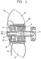
- FIG. 1 is a perspective view of the related art outer rotor type fan-motor.
- the outer rotor type fan-motor 10 includes a rear bearing assembly 14 substantially attached to a casing (not shown), a stator 11 attached to the rear bearing assembly 14, a front bearing assembly 13 attached to the stator 11, a rotor 12 having a rotational shaft 15, which is supported to be freely rotated by the both bearing assemblies 13 and 14, at its central portion, and a fan unit 20 installed at an outer circumference of the rotor 12.
- the rotor 12 is disposed at an outer circumference of the stator 11 and has a cylindrical cup shape, and includes a permanent magnet 12a attached on an inner circumferential surface of the rotor 12.
- One end portion of the rotational shaft 15 is fixedly press-fit at a central portion of one end portion of the rotor 12.
- the rotational shaft 15 is rotatably supported by the front bearing assembly 13 and the rear bearing assembly 14, and the permanent magnet 12 is disposed to face the stator 11 with a slight space therebetween.
- the fan unit 20 is made of a synthetic resin material and includes a hub 22 that covers the outer circumferential portion of the rotor 12 and a plurality of blades 21 extending in a diameter direction on an outer circumferential surface of the hub 22.
- a shaft fixing part 22a to be combined with the rotational shaft 15 is protrusively formed at the central portion of the hub 22.
- the outer rotor type fan-motor 10 may be constructed by directly attaching the permanent magnet 12 on an inner surface of the hub 22.
- the outer circumference of the rotor 12 directly contacts and is combined with an inner surface of the bottom of the hub 22 of the fan unit 20.
- the rotor 12 is rotated according to interaction between the stator 11 and the rotor 12, and as the hub 22 combined by directly contacting with an outer surface of the rotor 12 is rotated together with the rotor 12, the fan unit 20 is rotated.
- an embossing surface is formed to minimize a contact portion in combining the rotor 12 or the permanent magnet 12 and the hub 22, but in this case, a partial noise is still emanated through the fan unit 20.
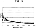
- the emanated noise in the related art outer rotor type fan-motor, as shown in FIG. 3 , a large amount of high frequency noise is generated in the frequency range of 2000 Hz or higher. In addition to the problem of the generation of the high frequency noise, the high frequency noise has a bad influence on the durability of the outer rotor type fan-motor especially in a resonated state.
- WO 99/57795 A1 relates to a first and second stator circuitry for respective use with first and second stators in a multi-stator motor configured so that the first stator circuitry is substantially unaffected by a failure of the second stator circuitry to energize a second winding in the second stator.
- US 6 339 267 B1 relates to a motor apparatus that may be used for blower motors in vehicular air conditioner systems.
- EP 1 063 752 A1 relates to electric motors and more particular to brushless motors suitable for driving a blower used in an automotive air conditioning device.
- the present invention is designed to solve such problem of the related art, and therefore, one object of the present invention is to provide an outer rotor type fan-motor capable of reducing vibration or a high frequency noise by preventing vibration of a permanent magnet excited by an electromagnetic exciting force from being directly transferred to a fan.
- Another object of the present invention is to provide an outer rotor type fan-motor capable of maintaining a combining force between a rotational shaft and a fan for a long time.
- an outer rotor type fan-motor including: a rotational shaft; a stator installed at an outer side of the rotational shaft; a permanent magnet assembly that covers an outer side of the stator at a certain distance and is installed at the rotational shaft; and a fan, at which the rotational shaft is fixed, that rotates together with the rotational shaft and includes a hub that covers an outer side of the permanent magnet assembly and blades formed on an outer surface of the hub, wherein an inner surface of the hub and an outer surface of the permanent magnet assembly are separated.
- an exciting force generated from a permanent magnet or the permanent magnet assembly cannot be directly transferred to the fan but can be transferred through the rotational shaft, to thus reduce a high frequency noise.
- the permanent magnet assembly is combined only to the rotational shaft.
- the permanent magnet assembly has a cylindrical shape with one side opened and the other side thereof is combined with the rotational shaft. Accordingly, rotation of the permanent magnet assembly is transferred to the rotational shaft and rotation of the rotational shaft is transferred to the fan, resulting in that noise or exciting force of the permanent magnet assembly is transferred through the rotational shaft, not through the fan.
- a step is formed along the circumstance of a rotational shaft insertion hole of the inner surface of the hub, through which the rotational shaft is fixedly combined, and a step is formed on an inner surface of the shaft fixing part.
- the permanent magnet assembly is formed as an elastic body.
- the permanent magnet assembly can absorb the exciting force generated from the permanent magnet attached to the permanent magnet assembly.
- a stopper for limiting an insertion depth of the rotational shaft is mounted at the shaft fixing part.
- the stopper can prevent an outer surface of the permanent magnet assembly combined with the rotational shaft from directly contacting with the inner surface of the hub by limiting the depth with which the rotational shaft is inserted into the shaft fixing part of the hub.
- the stopper may be integrally formed with the shaft fixing part.
- integrally forming the stopper with the shaft fixing part a process for installing the stopper at the shaft fixing part can be omitted, so the productivity and assembling characteristics of the fan can be improved.
- a spring for maintaining the combining force between the fan and the rotational shaft is mounted on an outer surface of the shaft fixing part, and preferably, the spring has a cylindrical shape with one side where a slit is formed. Accordingly, the combining force between the shaft fixing part and the rotational shaft can be uniformly maintained, and possible weakening of the combining force between the rotational shaft and the shaft fixing part due to abrasion as the fan is used for a long time period can be prevented.
- an adhesive for fixing the rotational shaft on the inner surface of the shaft fixing part may be applied to maintain the combining force between the rotational shaft and the shaft fixing part.
- a sound-absorbing member may be mounted on at least one of the outer surface of the permanent magnet assembly or the inner surface of the hub. This is to doubly prevent noise or vibration caused as the permanent magnet is excited from being transferred to the fan, together with the structure for combining the permanent magnet assembly and the hub.
- an outer rotor type fan-motor including: a rotational shaft; a stator installed at an outer side of the rotational shaft; a permanent magnet assembly that covers an outer side of the stator at a certain distance and is installed at the rotational shaft; and a fan that includes a shaft fixing part for fixing the rotational shaft, a hub for covering an outer side of the permanent magnet assembly and blades formed on an outer surface of the hub, wherein an insulation space is formed between the permanent magnet assembly and the fan to reduce vibration or noise of the permanent magnet assembly from being transferred to the fan.
- the permanent magnet assembly includes a cylindrical permanent magnet mounting part and a disk-type shaft support part that covers one end of the permanent magnet mounting part.
- a permanent magnet is mounted on an inner surface of the permanent magnet mounting part and is installed to be spaced apart from the stator. This it to form an air gap between the permanent magnet assembly serving as a rotor and the stator.
- a shaft tube through hole through which the rotational shaft is insertedly fixed, is formed at a central portion of the shaft support part, and a flange part is protrusively formed along the circumference of the shaft tube through hole.
- the flange part serves to prevent degradation of strength of the shaft tube through hole.
- the insulation space is formed between an outer surface of the permanent magnet mounting part and an inner surface of the hub and between an outer surface of the shaft support part and the inner surface of the hub. Namely, by forming the insulation space over the entire outer surface of the permanent magnet assembly, the fan and the permanent magnet assembly can be prevented from directly contacting with each other.
- the space between the outer surface of the shaft support part and the inner surface of the hub is smaller than the space between the outer surface of the permanent magnet mounting part and the inner surface of the hub. The reason is to prevent occurrence of a resonance phenomenon as vibration caused by rotation of the blades formed on the outer surface of the hub positioned at the outer side of the permanent magnet mounting part is directly transferred to the permanent magnet assembly.
- a bearing assembly that rotatably supports the rotational shaft is installed between the rotational shaft and the stator, and preferably, a bearing of the bearing assembly is an oilless bearing that does not need oil.
- the outer rotor type fan-motor according to the present invention can reduce vibration or high frequency noise by forming a vibration noise insulation space between the inner surface of the hub of the fan and the outer surface of the permanent magnet assembly to thus prevent the fan and the permanent magnet assembly from directly contacting with each other.
- the outer rotor type fan-motor because the rotational shaft and the fan are combined with the spring or the adhesive, the combining force between the rotational shaft and the fan can be uniformly maintained, and thus, the combining force cannot deteriorate in spite of a long time use.
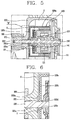
- FIG. 4 is a sectional view showing an outer rotor type fan-motor according to an embodiment of the present invention
- FIG. 5 is an enlarged view of a portion 'A' in FIG. 4
- FIG. 6 is an enlarged view of a portion 'B' in FIG. 5
- FIGs. 7 and 8 are perspective views of the outer rotor type fan-motor in FIG. 4
- FIG. 9 is a graph showing experimental data of a relationship between frequency and noise of the outer rotor type fan-motor in FIG. 4
- FIG. 10 is a view schematically showing an inner section of a refrigerator employing the outer rotor type fan-motor according to the embodiment of the present invention.
- the outer rotor type fan-motor includes a rotational shaft 150 , a pair of bearing assemblies 130 and 140 that rotatably support the rotational shaft 150, a stator 110 that fixedly mounted at an outer side of the pair of bearing assemblies 130 and 140, a permanent magnet assembly 120 installed at an outer side of the stator 110, a permanent magnet 121 mounted at the permanent magnet assembly 120, and a fan unit 200 that houses the permanent magnet assembly 120, one end of the rotational shaft 150 being fixedly combined with the fan unit 200.
- the bearing assemblies 130 and 140 include bearings 131 and 141 that are formed to rotatably support the rotational shaft 150 and platy oil felts 132 and 142 installed on an outer circumferential surface of the bearings 131 and 141.
- the oil felts 132 and 142 contain oil by themselves, so the bearings 131 and 141 can be operated without any additional oil. Namely, oilless bearing can be implemented.
- the bearings 131 and 141 and the oil felts 132 and 142 are supported by platy bearing frames 133 and 143 to thus form the respective bearing assemblies 130 and 140.
- a release preventing ring 144 is installed at one end of the rotational shaft 150 rotatably supported by the lower bearing assembly 140.
- the stator 110 is fixedly installed along a circumferential direction at an outer side of the pair of bearing assemblies 130 and 140, and a bobbin (not shown) wound with winding coil 111 is installed at the stator 110.
- the permanent magnet 121 is installed at an outer circumference of the stator with a certain space therebetween.
- the permanent magnet 121 is mounted at the permanent magnet assembly 120 which is formed substantially in a cylindrical shape or in a cup shape with one side opened and the other side closed.
- the permanent magnet assembly 120 serves as a rotor by itself.
- a fan 200 is installed at an outer circumference of the permanent magnet assembly 120 such that a space is formed to be separated from an outer surface of the permanent magnet assembly 120.
- the fan 200 is an axial flow fan that includes a hub 220 formed to house the permanent magnet assembly 120, a plurality of blades 210 formed on the outer surface of the hub 220, and a shaft fixing part 221 formed to be protruded from a central portion of the outer surface of the hub, in which the rotational shaft 150 is fixedly combined.
- the present invention is not limited thereto.
- a centrifugal fan, a turbo fan, and the like may be adopted according to the size of cooling capacity required by a refrigerator employing the fan 200.
- a stopper 222 for limiting the depth at which the rotational is inserted is installed at one end of the shaft fixing part 221, and a spring 160 for maintaining the combining force with the rotational shaft 150 is installed at an outer surface of the shaft fixing part 221.
- the shaft fixing part 221 protrusively formed at the central portion of the outer surface of the hub 220 of the fan 200 includes a rotational shaft insertion hole 221 b in which the rotational shaft 150 is fixedly combined.
- the stopper 222 for limiting the depth with which the rotational shaft 150 is inserted is formed at one end in the opposite direction in which the rotational shaft 150 is inserted.
- the stopper 222 serves to prevent the outer surface of the permanent magnet assembly 120 from contacting with the inner surface of the hub 220 by limiting the depth with which the rotational shaft 150 is inserted in the shaft fixing part 221.
- the stopper 222 may be formed as a separate member to be inserted into the rotational shaft insertion hole 221b of the shaft fixing part 221, or may be integrally formed with the shaft fixing part 221.
- a step may be formed at one end of the inner surface of the rotational shaft insertion hole 221 b of the shaft fixing part 221 to limit the depth with which the rotational shaft 150 is inserted.
- the substantially cylindrical spring 160 is mounted on an outer surface of the shaft fixing part 221. Because the spring 160 is installed on the outer surface of the shaft fixing part 221, the combining force between the rotational shaft 150 and the shaft fixing part 221 can be uniformly maintained and can be prevented from being degraded in spite of a long time use.
- the spring 160 has the substantially cylindrical shape, and preferably, includes a slit (not shown) that penetrates the thickness thereof to facilitate its installation at the shaft fixing part 221 with an elastic restoration force.
- an adhesive may be applied to the rotational shaft insertion hole 221 b of the shaft fixing part 221 and the rotational shaft 150 is then insertedly combined therein.
- the permanent magnet assembly 120 is installed within the hub 220 of the fan 200, and in this case, the outer surface of the permanent magnet assembly 120 and the inner surface of the hub 220 do not contact with each other. In other words, the outer surface of the permanent magnet assembly 120 and the inner surface of the hub 220 are separated, between which a vibration noise insulation space (S) is formed.
- S vibration noise insulation space
- the inner surface of the permanent assembly 120 is installed to be separated from the stator 110, and the outer surface of the permanent magnet assembly 120 is separated from the inner surface of the hub 220.
- the permanent magnet assembly 120 has the cylindrical shape or the cup shape such that one side thereof is opened, in which the stator 110 is installed, the other side of the permanent magnet assembly 120 is closed, and a shaft through hole 120c is formed at a central portion thereof, through which the rotational shaft 150 is insertedly fixed.
- the permanent magnet assembly 120 includes a permanent magnet mounting part 120a formed in a cylindrical shape or formed like a circular wall, and a disk-type shaft support part 120b that is integrally formed with one end of the permanent magnet mounting part 120a.
- the permanent magnet assembly 120 is formed as an elastic body in order to absorb noise or vibration caused by the electromagnetic exciting force of the permanent magnet 121 and emanated to the fan 200.
- the permanent magnet 121 is mounted on the inner surface of the permanent magnet mounting part 120a, and the permanent magnet 121 is mounted to be spaced apart from the stator 110.
- the permanent magnet 121 is made of plastic, on which parylene is coated to improve moisture-resistance reliability. Because the permanent magnet 121 is made of plastic, polar anisotropy magnetization can be easily made.
- a shaft through hole 120c is formed at the central portion of the shaft support part 120b, through which the rotational shaft 150 penetrates to be fixed.
- a flange part 120d is protrusively formed at upper and lower portions along the periphery of the shaft through hole 120c in order to prevent degradation of strength that may be caused by the formation of the shaft through hole 120c.
- the flange part 120d is installed to be separated from the bearing assembly 130 and the hub 220.
- the outer surface of the permanent magnet mounting part 120a is separated from the inner surface of the hub 220 to form the vibration noise insulation space (S), and the outer surface of the shaft support part 120b is separated from the inner surface of the hub 220 to form the vibration noise insulation space (S).
- the space between the outer surface of the shaft support part 120b and the inner surface of the hub 220 is narrower than the space between the outer surface of the permanent magnet mounting part 120a and the inner surface of the hub 220. The reason is to reduce a resonance phenomenon that since the blades 210 are formed on the outer surface of the hub 220 adjacent to the permanent magnet mounting part 120a, vibration due to the rotation of the blades 210 is directly transferred to the permanent magnet assembly 120, causing the resonance phenomenon.
- a step 221 a is formed along a lengthwise direction of the rotational shaft 150 at the inner surface of the shaft fixing part 221, and a step 220a is formed along the circumference of the rotational shaft insertion hole 221 b for combining the rotational shaft 150 of the inner surface of the hub 220.
- the flange part 120d of the permanent magnet assembly 120 can be prevented from contacting with the inner surface of the hub 220 of the fan 200.
- a sound-absorbing member (not shown) may be mounted at least one of the outer surface of the permanent magnet assembly 120 and the inner surface of the hub 220.
- the vibration noise insulation space (s) is formed between the permanent magnet assembly 120 and the hub 220 of the fan 200, or because the sound-absorbing member (not shown) is installed together with the formation of the insulation noise insulation space (S), a direct transfer of the vibration or high frequency noise generated due to the excitation of the permanent magnet 121 to the fan 200 can be effectively prevented.
- FIGs. 7 and 8 are perspective views of the outer rotor type fan-motor with an axial flow fan according to the embodiment of the present invention.
- a refrigerator employing the outer rotor type fan-motor 100 includes: evaporators 320 and 420 installed, respectively, at a freezing chamber 300 and a refrigerating chamber 400; the outer rotor type fan-motors 100 that are installed at the freezing chamber 300 and at the refrigerating chamber 400 to blow cooling air thereinto and include the rotational shaft 150, the bearing assemblies 130 and 140 rotatably supporting the rotational shaft 150, a stator 110 installed at the outer side of the bearing assemblies 130 and 140, the permanent magnet assembly 120 covering the outer side of the stator at a certain distance and installed at the rotational shaft 150, and the fan 200 having the hub 220 with the shaft fixing part 221 for fixing the rotational shaft 150 and covering the outer side of the permanent magnet assembly 120 at a certain distance and the blades 210 formed around the hub 220, the insulation space (S) for preventing vibration and noise of the permanent magnet assembly 120 from being transferred to the fan 200 being formed between the permanent magnet assembly 120 and the fan
- Reference numeral 310 denotes a cooling air inlet of the freezing chamber 300
- 410 denotes a cooling air inlet of the refrigerating chamber 400.
- the rotational shaft 150 combined in the shaft through hole 120c of the permanent magnet assembly 120 is rotated and the fan 200 having the shaft fixing part 21 in which the rotational shaft 150 is fixed is also rotated to supply cooling air to the freezing chamber 300 or to the refrigerating chamber 400 through the cooling air ducts 330 and 340 of the refrigerator 500.
- the permanent magnet assembly 120 and the hub 220 are separately installed to form the vibration noise insulation space (S) between the permanent magnet assembly 120 and the hub 220, the electromagnetic exciting force generated through the space between the permanent magnet 121 and the stator 110 is transferred to the fan 200 through the rotational shaft 150, rather than being directly transferred to the fan 200, and thus, generation of the high frequency noise can be reduced.
- S vibration noise insulation space
- the combining force between the rotational shaft 150 and the shaft fixing part 221 can be uniformly maintained for a long time.
- the outer rotor type fan-motor according to the embodiment of the present invention can be applicable to various electric devices as well as a freezing device such as the refrigerator or an air-conditioning system such as an air-conditioner.
Landscapes
- Engineering & Computer Science (AREA)
- Mechanical Engineering (AREA)
- General Engineering & Computer Science (AREA)
- Power Engineering (AREA)
- Connection Of Motors, Electrical Generators, Mechanical Devices, And The Like (AREA)
- Structures Of Non-Positive Displacement Pumps (AREA)
- Permanent Magnet Type Synchronous Machine (AREA)
Claims (11)
- Moteur de ventilateur à rotor externe qui comprend :un arbre de rotation (150) ;un stator (110) installé sur un côté extérieur de l'arbre de rotation (150) ;un aimant permanent (120) qui recouvre un côté extérieur du stator (110) à une certaine distance, et est installé au niveau de l'arbre de rotation (150) ; etun ventilateur (200), au niveau duquel l'arbre de rotation (150) est fixé, et qui tourne avec l'arbre de rotation (150) et comprend un moyeu (220) qui recouvre un côté extérieur de l'aimant permanent (120) et des pales (210) formées sur une surface extérieure du moyeu (220),dans lequel une surface intérieure du moyeu (220) et une surface extérieure de l'aimant permanent (120) sont séparées,caractérisé en ce qu'une partie de fixation d'arbre (221) est formée afin de faire saillie d'une partie centrale de la surface extérieure du moyeu (220), la partie de fixation d'arbre (221) ayant un trou d'insertion d'arbre de rotation (221 b) dans lequel l'arbre de rotation (150) est fixé,dans lequel l'aimant permanent (120) comprend :une partie de montage d'aimant permanent (120a) cylindrique ; etune partie de support d'arbre sous forme de disque (120b) qui recouvre une extrémité de la partie de montage d'aimant permanent (120a),dans lequel l'espace situé entre la surface extérieure de la partie de support d'arbre (120b) et la surface intérieure du moyeu (220) est plus petit que l'espace situé entre la surface extérieure de la partie de montage d'aimant permanent (120a) et la surface intérieure du moyeu (220),dans lequel un rebord (221 a) est formé au niveau de la surface intérieure de la partie de fixation d'arbre (221) le long d'une direction longitudinale de l'arbre de rotation (150), etdans lequel un rebord (220a) est formé au niveau de la surface intérieure du moyeu (220) le long de la circonférence du trou d'insertion d'arbre de rotation (221b).
- Moteur de ventilateur selon la revendication 1, dans lequel l'aimant permanent (120) est formé comme un corps élastique destiné à absorber une force d'excitation électromagnétique générée par un espace situé entre le stator (110) et l'aimant permanent (120).
- Moteur de ventilateur selon la revendication 1, dans lequel une butée (222) destinée à limiter une profondeur d'insertion de l'arbre de rotation (150) est montée au niveau de la partie de fixation d'arbre (221).
- Moteur de ventilateur selon la revendication 3, dans lequel la butée (222) est intégralement formée avec la partie de fixation d'arbre (221).
- Moteur de ventilateur selon la revendication 1 ou 3, dans lequel un ressort (160) destiné à maintenir une force de combinaison entre le ventilateur et l'arbre de rotation (150) est montée sur la surface extérieure de la partie de fixation d'arbre (221).
- Moteur de ventilateur selon la revendication 5, dans lequel le ressort (160) possède une forme cylindrique avec une fente sur un de ces côtés.
- Moteur de ventilateur selon la revendication 1 ou 3, dans lequel un adhésif est appliqué sur la surface intérieure de la partie de fixation d'arbre (221) afin de maintenir la force de combinaison entre le ventilateur (200) et l'arbre de rotation (150).
- Moteur de ventilateur selon la revendication 1, dans lequel un élément qui absorbe le son est installé sur au moins l'une de la surface extérieure de l'aimant permanent (120) et de la surface intérieure du moyeu (220).
- Moteur de ventilateur selon l'une quelconque des revendications 1 à 8, dans lequel un aimant permanent (121) est monté sur une surface intérieure de la partie de montage d'aimant permanent (120a) et installé séparément à une certaine distance du stator (110).
- Moteur de ventilateur selon l'une quelconque des revendications 1 à 9, dans lequel un trou traversant d'arbre (120c) est formé au niveau d'une partie centrale de la partie de support d'arbre (120b), dans lequel l'arbre de rotation (150) est fixé par insertion, et une partie de flasque (120d) est formée en saillie le long de la circonférence du trou traversant d'arbre (120c).
- Moteur de ventilateur selon l'une quelconque des revendications 1 à 10, dans lequel un ensemble de roulements (130, 140) est installé entre l'arbre de rotation (150) et le stator (110) afin de supporter de manière rotative l'arbre de rotation (150), et un roulement de l'ensemble de roulements (130, 140) est un roulement sans huile qui n'a pas besoin d'huile.
Applications Claiming Priority (2)
| Application Number | Priority Date | Filing Date | Title |
|---|---|---|---|
| KR1020060083161A KR101189447B1 (ko) | 2006-08-30 | 2006-08-30 | 외전형 팬모터 |
| PCT/KR2007/004155 WO2008026876A1 (fr) | 2006-08-30 | 2007-08-29 | Moteur de ventilateur de type à rotor externe |
Publications (3)
| Publication Number | Publication Date |
|---|---|
| EP2057732A1 EP2057732A1 (fr) | 2009-05-13 |
| EP2057732A4 EP2057732A4 (fr) | 2014-04-02 |
| EP2057732B1 true EP2057732B1 (fr) | 2016-02-10 |
Family
ID=39136113
Family Applications (1)
| Application Number | Title | Priority Date | Filing Date |
|---|---|---|---|
| EP07808004.1A Not-in-force EP2057732B1 (fr) | 2006-08-30 | 2007-08-29 | Moteur de ventilateur de type à rotor externe |
Country Status (5)
| Country | Link |
|---|---|
| US (1) | US8057195B2 (fr) |
| EP (1) | EP2057732B1 (fr) |
| KR (1) | KR101189447B1 (fr) |
| CN (1) | CN101512876B (fr) |
| WO (1) | WO2008026876A1 (fr) |
Families Citing this family (10)
| Publication number | Priority date | Publication date | Assignee | Title |
|---|---|---|---|---|
| KR101495162B1 (ko) * | 2008-01-21 | 2015-02-24 | 엘지전자 주식회사 | 팬 조립체 및 이를 구비한 냉장고 |
| GB2467965B (en) | 2009-02-24 | 2015-04-22 | Dyson Technology Ltd | Rotor assembly |
| CN102678584A (zh) * | 2011-03-16 | 2012-09-19 | 乐金电子(天津)电器有限公司 | 分体式空调室内机风扇结构 |
| GB2493974B (en) | 2011-08-26 | 2014-01-15 | Dyson Technology Ltd | Bearing assembly |
| ITTO20111159A1 (it) * | 2011-12-15 | 2013-06-16 | Gate Srl | Motore elettrico per l'azionamento di una girante di un ventilatore per uno scambiatore di calore di un autoveicolo. |
| KR101454535B1 (ko) * | 2013-02-25 | 2014-10-24 | 뉴모텍(주) | 팬 모터 |
| KR102665313B1 (ko) * | 2016-09-19 | 2024-05-17 | 삼성전자주식회사 | 공기청정기 |
| EP3425204B1 (fr) * | 2017-07-04 | 2021-04-14 | Levitronix GmbH | Rotor magnétique et machine comprenant un tel rotor |
| CN111919034A (zh) * | 2018-03-29 | 2020-11-10 | 三菱电机株式会社 | 轴流叶片及鼓风机 |
| CN113623071B (zh) * | 2021-08-24 | 2025-06-24 | 鑫磊压缩机股份有限公司 | 一种用于燃气轮机的磁悬浮外转子启发一体电机 |
Family Cites Families (10)
| Publication number | Priority date | Publication date | Assignee | Title |
|---|---|---|---|---|
| US6437529B1 (en) | 1998-05-04 | 2002-08-20 | Comair Rotron, Inc. | Multi-stator motor with independent stator circuits |
| CN2358256Y (zh) * | 1998-11-13 | 2000-01-12 | 八明实业有限公司 | 双转子无刷直流风扇 |
| JP4077983B2 (ja) | 1999-06-25 | 2008-04-23 | カルソニックカンセイ株式会社 | 送風機用のブラシレスモータ |
| JP3706009B2 (ja) | 1999-09-01 | 2005-10-12 | アスモ株式会社 | ブラシレスモータ |
| KR100389116B1 (ko) | 2000-05-20 | 2003-06-25 | 장준석 | 객체의 목적지를 일관되게 참조할 수 있는 표현 방법 및그 시스템 |
| JP3682397B2 (ja) | 2000-02-28 | 2005-08-10 | 株式会社東芝 | ファンモータ |
| DE10131761A1 (de) * | 2001-06-30 | 2003-01-16 | Bosch Gmbh Robert | Elektrische Maschine |
| JP2003232296A (ja) | 2002-02-08 | 2003-08-22 | Sharp Corp | 送風ファン |
| KR20040047127A (ko) | 2002-11-29 | 2004-06-05 | 엘지이노텍 주식회사 | 컴퓨터용 팬 모터구조 |
| KR20050019351A (ko) | 2003-08-18 | 2005-03-03 | 엘지이노텍 주식회사 | 팬 모터 구조 |
-
2006
- 2006-08-30 KR KR1020060083161A patent/KR101189447B1/ko active Active
-
2007
- 2007-08-29 CN CN2007800323538A patent/CN101512876B/zh active Active
- 2007-08-29 EP EP07808004.1A patent/EP2057732B1/fr not_active Not-in-force
- 2007-08-29 US US12/439,043 patent/US8057195B2/en active Active
- 2007-08-29 WO PCT/KR2007/004155 patent/WO2008026876A1/fr not_active Ceased
Also Published As
| Publication number | Publication date |
|---|---|
| US20100014995A1 (en) | 2010-01-21 |
| WO2008026876A1 (fr) | 2008-03-06 |
| EP2057732A4 (fr) | 2014-04-02 |
| KR101189447B1 (ko) | 2012-10-09 |
| KR20080020139A (ko) | 2008-03-05 |
| EP2057732A1 (fr) | 2009-05-13 |
| CN101512876A (zh) | 2009-08-19 |
| CN101512876B (zh) | 2012-07-18 |
| US8057195B2 (en) | 2011-11-15 |
Similar Documents
| Publication | Publication Date | Title |
|---|---|---|
| EP2057732B1 (fr) | Moteur de ventilateur de type à rotor externe | |
| JP4465354B2 (ja) | 電動モータのためのデカップリング装置および電動モータを製作する方法 | |
| US8573954B2 (en) | Fan assembly | |
| JP2018125920A (ja) | アウターロータ型モータ | |
| US9214840B2 (en) | Fan motor, on-vehicle air conditioner using the fan motor, and method for assembling fan motor | |
| US20170040864A1 (en) | Electric Compressor | |
| CN105805019B (zh) | 离心泵 | |
| EP2080906B1 (fr) | Ensemble de ventilateur | |
| US8836189B2 (en) | Spindle motor having lubricant filled bearing clearance | |
| KR101461240B1 (ko) | 팬 모터 | |
| JP2000283099A (ja) | ファン装置 | |
| JP7234456B2 (ja) | 電動機、送風機及び空気調和装置 | |
| KR101463817B1 (ko) | 모터 및 팬-모터 조립체 | |
| CN217057720U (zh) | 空调器 | |
| US20220247245A1 (en) | Ec motor, fan with ec motor, and household appliance | |
| AU2020203472B2 (en) | Motor assembly and manufacturing method thereof | |
| KR101492272B1 (ko) | 팬 | |
| JP7652104B2 (ja) | 車載用電動圧縮機 | |
| CN1312827C (zh) | 电机激励器 | |
| JPH11182488A (ja) | 送風機 | |
| KR101988799B1 (ko) | 마그넷 홀더가 결합된 일체형 요크를 갖는 차량용 직류 모터 | |
| JPH09191624A (ja) | ブラシレスモータ | |
| JP2005137068A (ja) | アウターロータ型モータ | |
| KR20100029620A (ko) | 팬모터의 팬 | |
| KR20080079481A (ko) | 공기조화기의 송풍기 |
Legal Events
| Date | Code | Title | Description |
|---|---|---|---|
| PUAI | Public reference made under article 153(3) epc to a published international application that has entered the european phase |
Free format text: ORIGINAL CODE: 0009012 |
|
| 17P | Request for examination filed |
Effective date: 20090311 |
|
| AK | Designated contracting states |
Kind code of ref document: A1 Designated state(s): AT BE BG CH CY CZ DE DK EE ES FI FR GB GR HU IE IS IT LI LT LU LV MC MT NL PL PT RO SE SI SK TR |
|
| AX | Request for extension of the european patent |
Extension state: AL BA HR MK RS |
|
| DAX | Request for extension of the european patent (deleted) | ||
| RBV | Designated contracting states (corrected) |
Designated state(s): DE GB IT |
|
| A4 | Supplementary search report drawn up and despatched |
Effective date: 20140228 |
|
| RIC1 | Information provided on ipc code assigned before grant |
Ipc: F04D 29/26 20060101ALI20140224BHEP Ipc: F04D 29/66 20060101ALI20140224BHEP Ipc: F04D 25/06 20060101ALI20140224BHEP Ipc: H02K 1/30 20060101ALI20140224BHEP Ipc: H02K 29/00 20060101ALI20140224BHEP Ipc: F04D 29/32 20060101ALI20140224BHEP Ipc: H02K 21/22 20060101ALI20140224BHEP Ipc: H02K 5/24 20060101AFI20140224BHEP |
|
| GRAP | Despatch of communication of intention to grant a patent |
Free format text: ORIGINAL CODE: EPIDOSNIGR1 |
|
| INTG | Intention to grant announced |
Effective date: 20150724 |
|
| RIN1 | Information on inventor provided before grant (corrected) |
Inventor name: LEE, DONG-IL Inventor name: SHIN, HYOUN-JEONG |
|
| GRAS | Grant fee paid |
Free format text: ORIGINAL CODE: EPIDOSNIGR3 |
|
| GRAA | (expected) grant |
Free format text: ORIGINAL CODE: 0009210 |
|
| AK | Designated contracting states |
Kind code of ref document: B1 Designated state(s): DE GB IT |
|
| REG | Reference to a national code |
Ref country code: GB Ref legal event code: FG4D |
|
| REG | Reference to a national code |
Ref country code: DE Ref legal event code: R096 Ref document number: 602007044822 Country of ref document: DE |
|
| PG25 | Lapsed in a contracting state [announced via postgrant information from national office to epo] |
Ref country code: IT Free format text: LAPSE BECAUSE OF FAILURE TO SUBMIT A TRANSLATION OF THE DESCRIPTION OR TO PAY THE FEE WITHIN THE PRESCRIBED TIME-LIMIT Effective date: 20160210 |
|
| REG | Reference to a national code |
Ref country code: DE Ref legal event code: R097 Ref document number: 602007044822 Country of ref document: DE |
|
| PLBE | No opposition filed within time limit |
Free format text: ORIGINAL CODE: 0009261 |
|
| STAA | Information on the status of an ep patent application or granted ep patent |
Free format text: STATUS: NO OPPOSITION FILED WITHIN TIME LIMIT |
|
| 26N | No opposition filed |
Effective date: 20161111 |
|
| PGFP | Annual fee paid to national office [announced via postgrant information from national office to epo] |
Ref country code: GB Payment date: 20210707 Year of fee payment: 15 |
|
| GBPC | Gb: european patent ceased through non-payment of renewal fee |
Effective date: 20220829 |
|
| PG25 | Lapsed in a contracting state [announced via postgrant information from national office to epo] |
Ref country code: GB Free format text: LAPSE BECAUSE OF NON-PAYMENT OF DUE FEES Effective date: 20220829 |
|
| PGFP | Annual fee paid to national office [announced via postgrant information from national office to epo] |
Ref country code: DE Payment date: 20240705 Year of fee payment: 18 |
|
| REG | Reference to a national code |
Ref country code: DE Ref legal event code: R119 Ref document number: 602007044822 Country of ref document: DE |