EP2058148B1 - Installation de réglage de la pression des pneus et procédé de réglage de la pression des pneus - Google Patents
Installation de réglage de la pression des pneus et procédé de réglage de la pression des pneus Download PDFInfo
- Publication number
- EP2058148B1 EP2058148B1 EP08019551A EP08019551A EP2058148B1 EP 2058148 B1 EP2058148 B1 EP 2058148B1 EP 08019551 A EP08019551 A EP 08019551A EP 08019551 A EP08019551 A EP 08019551A EP 2058148 B1 EP2058148 B1 EP 2058148B1
- Authority
- EP
- European Patent Office
- Prior art keywords
- pressure
- wheel
- valve
- control
- supply line
- Prior art date
- Legal status (The legal status is an assumption and is not a legal conclusion. Google has not performed a legal analysis and makes no representation as to the accuracy of the status listed.)
- Not-in-force
Links
- 238000000034 method Methods 0.000 title claims abstract description 14
- 230000008859 change Effects 0.000 claims abstract description 13
- 238000012544 monitoring process Methods 0.000 claims abstract description 7
- 230000000903 blocking effect Effects 0.000 claims description 16
- 230000001105 regulatory effect Effects 0.000 claims description 12
- 230000008569 process Effects 0.000 claims description 6
- 238000010276 construction Methods 0.000 claims description 3
- 230000001276 controlling effect Effects 0.000 claims description 2
- 230000007935 neutral effect Effects 0.000 description 22
- 230000007704 transition Effects 0.000 description 13
- 230000008901 benefit Effects 0.000 description 3
- 230000000694 effects Effects 0.000 description 3
- 230000009467 reduction Effects 0.000 description 3
- ORQBXQOJMQIAOY-UHFFFAOYSA-N nobelium Chemical compound [No] ORQBXQOJMQIAOY-UHFFFAOYSA-N 0.000 description 2
- 230000006978 adaptation Effects 0.000 description 1
- 238000005516 engineering process Methods 0.000 description 1
- 239000000945 filler Substances 0.000 description 1
- 238000005429 filling process Methods 0.000 description 1
- 238000001208 nuclear magnetic resonance pulse sequence Methods 0.000 description 1
- 238000009420 retrofitting Methods 0.000 description 1
- 239000000725 suspension Substances 0.000 description 1
- 230000002123 temporal effect Effects 0.000 description 1
- 238000011144 upstream manufacturing Methods 0.000 description 1
- 238000009423 ventilation Methods 0.000 description 1
Images




Classifications
-
- B—PERFORMING OPERATIONS; TRANSPORTING
- B60—VEHICLES IN GENERAL
- B60C—VEHICLE TYRES; TYRE INFLATION; TYRE CHANGING; CONNECTING VALVES TO INFLATABLE ELASTIC BODIES IN GENERAL; DEVICES OR ARRANGEMENTS RELATED TO TYRES
- B60C23/00—Devices for measuring, signalling, controlling, or distributing tyre pressure or temperature, specially adapted for mounting on vehicles; Arrangement of tyre inflating devices on vehicles, e.g. of pumps or of tanks; Tyre cooling arrangements
- B60C23/001—Devices for manually or automatically controlling or distributing tyre pressure whilst the vehicle is moving
- B60C23/002—Devices for manually or automatically controlling or distributing tyre pressure whilst the vehicle is moving by monitoring conditions other than tyre pressure or deformation
-
- B—PERFORMING OPERATIONS; TRANSPORTING
- B60—VEHICLES IN GENERAL
- B60C—VEHICLE TYRES; TYRE INFLATION; TYRE CHANGING; CONNECTING VALVES TO INFLATABLE ELASTIC BODIES IN GENERAL; DEVICES OR ARRANGEMENTS RELATED TO TYRES
- B60C23/00—Devices for measuring, signalling, controlling, or distributing tyre pressure or temperature, specially adapted for mounting on vehicles; Arrangement of tyre inflating devices on vehicles, e.g. of pumps or of tanks; Tyre cooling arrangements
- B60C23/001—Devices for manually or automatically controlling or distributing tyre pressure whilst the vehicle is moving
- B60C23/003—Devices for manually or automatically controlling or distributing tyre pressure whilst the vehicle is moving comprising rotational joints between vehicle-mounted pressure sources and the tyres
- B60C23/00354—Details of valves
-
- B—PERFORMING OPERATIONS; TRANSPORTING
- B60—VEHICLES IN GENERAL
- B60C—VEHICLE TYRES; TYRE INFLATION; TYRE CHANGING; CONNECTING VALVES TO INFLATABLE ELASTIC BODIES IN GENERAL; DEVICES OR ARRANGEMENTS RELATED TO TYRES
- B60C23/00—Devices for measuring, signalling, controlling, or distributing tyre pressure or temperature, specially adapted for mounting on vehicles; Arrangement of tyre inflating devices on vehicles, e.g. of pumps or of tanks; Tyre cooling arrangements
- B60C23/001—Devices for manually or automatically controlling or distributing tyre pressure whilst the vehicle is moving
- B60C23/003—Devices for manually or automatically controlling or distributing tyre pressure whilst the vehicle is moving comprising rotational joints between vehicle-mounted pressure sources and the tyres
- B60C23/00372—Devices for manually or automatically controlling or distributing tyre pressure whilst the vehicle is moving comprising rotational joints between vehicle-mounted pressure sources and the tyres characterised by fluid diagrams
Definitions
- the driving behavior of a motor vehicle and possibly also that of a trailer also depend crucially on the tire inflation pressures.
- Any chosen tire inflation pressure is basically a compromise, for example, in favor or at the expense of handling, comfort or possible traction.
- the tire inflation pressures can also affect the driving safety or the economy of a vehicle. Different load conditions, speeds and road conditions require appropriately adjusted tire inflation pressures for optimal driving and wear behavior. It would be desirable to be able to change the tire inflation pressures from the vehicle while driving.
- lift axles are often used. This allows the number of effective axes to be adapted to the load condition. Tire wear, vehicle economy, and idle driving performance can all be improved by lifting one or more axles.
- the invention relates to a tire pressure regulating system according to the features of the first main claim. Furthermore, the invention relates to a method for regulating the tire pressure according to the features of the first method claim.
- the system according to DE 32 46 601 A1 uses pressure surges to open special wheel valves and later close them again.
- the level of pressure surges is above the pressure level at which the tires are filled.
- the supply lines are vented again.
- Such a trained device is also off DE 34 05 111 C2 known.
- Two regulated tires are connected via a wheel valve to a common supply line.
- the common supply line and the control valve influence the filling pressures of these tires.
- the control valve generates three pressure levels on the supply line: an opening pressure, a pressure which is reduced comparatively quickly, or a pressure which is reduced comparatively slowly.
- a tire inflation device which has a wheel valve which is movable between a blocking position and a passage position and designed as a pressure-controlled flip-flop.
- the position of the flip-flop valve does not depend on the currently present in the supply line pressure level, but of the hitherto taken place in the supply line transitions in the form of "no pressure” to "pressure present".
- the idea of exploiting pressure jumps to control wheel valves is taken up and further developed here.
- the subject of claim 1 is based on the object to realize a tire pressure control system that allows an individual influence on the inflation pressures in tires, with a simple, inexpensive and compact design.
- this object is achieved according to claim 1, characterized in that the pressure level is determined by a control valve in a supply line common to several tires, being distinguished only between the states “pressure-less” and “pressure present”, and resulting pressure level changes to control at least one serve appropriately designed wheel valve.
- This simple design is an individual influencing the filling pressures in tires.
- the inventive method (claim 13) for controlling the tire pressure and a tire pressure control system according to the invention (claim 1) have the advantage that in the simplest way only two pressure conditions must be provided by the system, and that also several, pneumatically and possibly also kinematically separated tires can be controlled individually via a common supply line and thus also via a common control valve.
- the "non-pressurized” state corresponds to the natural ambient pressure that occurs in a vented supply line, while the state “pressure present” does not necessarily require a specific, fixed pressure value. Rather, the pressure in the state “pressure present” may move in a wide range, only a certain minimum pressure must be maintained, so that the two states “pressure present” and “pressure-less” can be safely distinguished from each other.
- a tire to be filled will not reach a higher pressure than specified by the condition "pressure present”.
- a tire pressure control system can also be constructed very cost-effective, since in particular to the rotor connections are not made too high demands. The system would still work satisfactorily, if the applicable as critical components rotor connections should have small leaks. Also, the rotating part of the tire pressure control system can be realized inexpensively, because depending on the selected embodiment (variant) can be used for the pressure-controlled wheel valves on conventional valve units.
- Fig.1 shows a tire pressure control system in a schematic representation.
- Figure 13 shows a tire pressure control system with quick exhaust in a schematic representation.
- FIG.1 schematically illustrated tire pressure control system is based on a suspension concept with single-tire front axle and twin-rear axle, typical of a commercial vehicle.
- the six tires shown are controlled individually via a total of three control valves and correspondingly three supply lines.
- For each pair of tires regulated via a common line is in Fig.1 to demonstrate another technical solution presented.
- different variants can be combined within one system, but usually, unlike the one shown here, one will decide on at least one axis for a uniform embodiment.
- the tire pressure control system in Fig.1 is shown with all its valves in neutral position.
- the Einzelbereifte front axle is shown schematically, while the lower part of the drawing symbolizes the dual-tire rear axle.
- the plant has a compressor 1, which via a pressure regulator 2, a reservoir 3 z. B. with compressed air, but conceivable would be another medium supplied. From the reservoir pressure lines lead to three 3/2-way solenoid valves 4, 5 and 6, which act as electrically responsive control valves.
- the 3/2-way solenoid valve or control valve 4 is responsible for the front axle. From him leads a supply line 10, which shares in its further course at the node 11, to the rotor or rotary joints 14 and 15 of the individual wheels of the front axle. In the neutral position, the supply line 10 is vented via the control valve 4, so that the rotor connections 14 and 15 are depressurized.
- each wheel has its own, separate wheel valve 21 or 22.
- the wheel valves are connected via the throttle bodies 31 and 32 with the individual tires 41 and 42, respectively.
- the wheel valve 22 of the left front wheel should be identical to the wheel valve 21 of the right front wheel.
- Both wheel valves are designed as so-called.
- Pneumatic flip-flops ie they have a control input 27 and 29 for pneumatic control and have two functional positions, namely a blocking position as a neutral position and a passage position as it were as working position.
- Such a wheel valve changes its position, for example, always when at its control input, a transition from "pressure-less” to "pressure present” occurs (switching with positive pressure jump, or in short: positive switching).
- the wheel valves can also be designed so that they always change their position when at their control inputs, a transition from "pressure present" to "pressure-less” (negative switching).
- the control input 27 of the wheel valve 21 for the right front wheel is connected via the control line 18 directly to the functional connection 26 of the wheel valve, which is connected via the rotor connection 14 and the node 11 to the supply line 10.
- the control input 27 of the wheel valve 21 is in operative connection with the supply line 10. If the control input 29 of the wheel valve 22 for the left front wheel also connected directly via the control line 19 to the rotor connection 15, so you could via the control valve 4 no targeted pressure increase in only perform one of the tires 41 or 42, because the identical wheel valves 21 and 22 would, both starting from the neutral position, take the same positions at any later time. That is why in Fig.1 the control input 29 of the wheel valve 22, a so-called. Pressure inverter 28 connected upstream.
- the pressure inverter 28 causes the control input 29 vented, that is, is depressurized when the control line 19 is under pressure, and vice versa, the control input 29 is precisely under pressure when the supply line 10 and thus the control line 19 is vented.
- the Pressure inverter itself can be formed, for example, from a pneumatic valve, a check valve and a small pressure accumulator, as in Fig.1 shown.
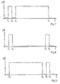
- a pressure curve in the supply line 10, such as in Figure 6 can be generated by applying a corresponding voltage waveform at the electrical control terminal 30 of the control valve 4 designed as a solenoid valve.
- a voltage curve can be generated by a push button, similar to a morse button.
- the voltage curve is generated by a central control unit 7, which operates as it were as an intelligent pulse generator.
- the central control unit 7 supplies the individual control valves 4, 5 and 6 with individual pulse sequences which result, for example, from a comparison of the target specifications (desired tire pressures) with the actual, current values. If the actual values match the targets, then no pulse trains are generated by the central controller 7.
- the targets can z. B.
- a manual input device 8 to the central control unit 7.
- the targets are fixed values.
- the actual, individual tire pressure values, ie the actual data, can be provided by a tire pressure monitoring system (TPMS). Suitable tire pressure monitoring systems have been state of the art for some time.
- Fig.1 is symbolically shown only the telemetry data receiver 9 of a corresponding tire pressure monitoring system. In conjunction with a complete tire pressure monitoring system can thus be in Fig.1 sketched tire pressure control as a closed loop realize.
- the wheel valve 21 reacts, it changes its position, so goes into on-position.
- the tire 41 is filled via the wheel valve 21 and the throttle body 31, provided, of course, that the pressure in the supply line 10, the supply pressure, is above the tire pressure.
- the supply line 10 is being vented, now also wheel valve 22 changes its position. Wheel valve 21 and wheel valve 22 are now both in the through position, the two tires 41 and 42 will now be emptied via the supply line 10 and ultimately via the control valve 4.
- the supply line 10 now acts as a return line.
- the throttles 31 and 32 ensure that this emptying is slow and that the supply line 10 and thus also the control lines 18 and 19 remain almost depressurized during emptying, thus can be done by the tire pressures no influence on the control of the wheel valves.
- the wheel valve 21 switches back into the blocking position, but the wheel valve 22 remains in the passage position. From now on, therefore, only the tire 42 is filled, namely, until the time t 4, the pressure in the supply line 10 is removed again.
- the wheel valve 22 changes back to its blocking position. The initial position, ie the neutral position as in Fig.1 pictured is restored. The tire pressure change process is completed.
- the 3/2-way solenoid valve or control valve 5 in Fig.1 is responsible for the two right tires 43 and 44 of the twin tires rear axle. Again, each wheel and thus each tire is assigned its own, separate wheel valve, and also here the two wheel valves 23 and 24 are formed as pneumatic flip-flops, each with a blocking and a respective passage position. In contrast to the front axle, where two identical wheel valves are used, however, the two wheel valves 23 and 24 differ in their structural design. The two signs "+” and "-” with which they are in Fig.1 are marked, should point out the constructive difference.
- the wheel valve 23 is positive switching, so it always changes its position when at its control input, a transition from "no pressure” to "pressure present” takes place.
- the wheel valve 24, however, is designed so that it always changes its position when at its control input, a transition from "pressure present” to “depressurized” takes place. The wheel valve 24 is thus negative switching.
- a supply line 12 leads to the rotor connection 16. Only after the rotor connection branches the supply line and leads to the two wheel valves 23 and 24. The control inputs of the two wheel valves 23 and 24 are in operative connection with the supply line 12. Between the wheel valves and the tires are still the throttle bodies 33 and 34.
- the tires 43 and 44 according to the same scheme, as has already been explained for the front axle, fill and empty.
- the in Figure 7 shown pressure profile, applied to the supply line 12 and starting from the neutral position, as a result to a filling of the inner tire, so lead to an increase in pressure in tire 44.
- the in Figure 9 Resulting pressure curve as a result to a filling of the outer tire, so to an increase in pressure in tires 43 lead.
- the 3/2-way solenoid valve or control valve 6 in Fig.1 is responsible for the two left tires 45 and 46 of twin tires rear axle. From there, a supply line 13 via a rotor connection 17 leads to a special wheel valve 25, which may also be referred to as Raditativentil 25, from where via the throttle bodies 35 and 36 each have a connection to the individual tires 45 and 46. It is conceivable that one of the tires, for example, the inner tire 45, is designed as a folding tire, which would shrink to a smaller diameter in the unpressurized state. In Fig.1 this is indicated by an additional dashed contour in tire 45.
- the special wheel group valve 25 may be a 3/4-way valve with additional pneumatic control port 37 which is pneumatically controllable such that at each transition from "non-pressurized” to "pressure present" at its control input 37 learns from one functional position to the next continues switching (positive switching), thereby having a cyclical behavior, ie after every four transitions from "pressure-less” to "pressure present” the original functional position is restored.
- the same objectives in principle can also be achieved with a negative-switching wheel valve 25.
- the wheel group valve 25 has a positive switching behavior.
- the four functional positions of the Raditatiils 25 is in detail to a blocking position and, so to speak, three working positions.
- both tires and the supply line are shut off, thus also pneumatically separated.
- the blocking position can also be referred to as a neutral position.
- a connection between the supply line 13 and the outer tire 46 is made while the inner tire 45 remains shut off.
- the inner tire 45 is connected to the supply line 13, while the outer tire 46 is shut off.
- the two tires 45 and 46 are connected to each other while the supply line is shut off.
- the Rad juryventil 25 switches a functional position on, so to speak, in its first working position, and the outer tire 46 is filled immediately.
- a pressure reduction takes place in the outer tire 46, namely, until the time t 3, the Rad juryventil again switches to its next, third functional position (second working position).
- the inner tire 45 is in operative connection with the supply line 13, but only as long as, until the time t 5, the Rad districtventil further switches into its fourth functional position. In this fourth operating position both tires 45 and 46 are pneumatically connected to each other, but at the same time separated from the supply line 13.
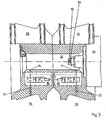
- a twin wheel pair is shown consisting of an inner wheel 51 and an outer wheel 52.
- the two wheel valves 61 and 62 are each contained in their associated wheel.
- a brake drum In the figure to the right of the wheel 50 can be seen, for. B. a brake drum. Wheel fasteners and tires are not shown.
- a hollow hub 53 is formed, which is closed by a cover 54 to the outside.
- the hollow hub is a large-volume branch point of a pressure line, and there are no pressure lines to be laid within the hub.
- the connection can be made from the hollow hub 53 to the rotor connection, not shown.
- the wheel valves 61 and 62 are connected via bores 71 and 74 to the hollow hub, via the further bores 72 and 75, they are connected to the tire inner spaces 73 and 76, respectively.
- the two wheel valves 61 and 62 are pneumatic flip-flops, as already described, but with the difference that the throttle points also already mentioned are integrated into the wheel valves.
- the wheel valve 62 always changes its position when at its control input, a transition from "pressure-less” to "pressure present” takes place, while the other wheel valve 61 always changes its position when at its control input, a transition from "pressure present” to " depressurized "takes place.
- the two signs in the drawing Fig.2 (+ and -) at the control inputs of the wheel valves should indicate the difference.
- FIG. 3 Also shown is a pair of twin wheels having an inner wheel 91 and an outer wheel 92, similar to FIG Fig.2 ,
- a common, special wheel valve 63 wheel group valve
- wheel group valve is used, which is designed as a 3/4-way valve with additional pneumatic control port 83 such that it switches from one functional position to the next with each pressure jump, which it registers at its control input 83 , It therefore changes both from one operating position to the next in the case of a transition from "pressure-less” to "pressure present” as well as in the transitions from "pressure present” to “pressure-less”, and has a cyclical behavior, ie after two pressure pulses his control input 83, so after four corresponding pressure jumps, the original position is restored.
- the wheel group valve 63 is in Figure 3 firmly connected to the cover 57, which closes the hollow hub 53 to the outside and here forms a protruding into the hollow hub pin.
- the hollow hub 53 in this case represents the branching from the axial bore 56 to the port 82 of the 3/4-way valve 63 and to its control input 83.
- About the separate pressure lines 77 and 78 is in each case a connection from the other two terminals of the Rad juryventils 63 made to the holes 79 and 80, respectively. These bores lead to the tire interiors 73 and 76 and each have a throttle point 81.
- the four functional positions of the 3/4-way valve 63 is a blocking position and three working positions. In the locked position both tires and the connection 82 of the Raditatiils are shut off.
- This position also represents the neutral position.
- the wheel group valve 63 is designed so that the blocking position can only be assumed when the control input 83 is depressurized. If the control input 83 is pressurized, the wheel group valve changes from the blocking position to its first working position. In this first working position, a connection is made from the port 82 to the pressure line 78, thus, in this position, the hollow hub 53 with the tire interior 76 (outer tire) connected while the inner tire remains locked. As soon as the pressure in the hollow hub 53 and thus also in the control input 83 changes from "pressure present" to "pressure-less", the wheel group valve then changes to its second working position.
- the three ports of the 3/4-way valve 63 are connected to each other via a node, ie the two tires, not shown, with their tire interiors 76 and 73 are now connected via the throttle points 81 with the now unpressurized hollow hub 53.
- the wheel group valve can assume its fourth functional position, ie its third working position, the hollow hub 53 must be pressurized again.
- the hollow hub 53 is connected to the tire interior 73 (inner tire), while the outer tire is shut off. If the pressure in the hollow hub is then removed again, then the wheel group valve again assumes the first functional position, ie the blocking position.
- FIG. 4 uses a common wheel valve, so a Rad juryventil, which is here, however, designed as a 3/3-way valve with additional pneumatic control port.
- Figure 4 is identical to Figure 3 , apart from the different wheel valves.
- the 3/3-way valve 64 in Figure 4 can be done in two different ways. It can have a positive switching behavior, ie it always changes from one Function position in the next, if at its control input, a transition from "pressure-less" to "pressure present” takes place.
- the wheel group valve 64 can also be designed to be negative switching. Since it also has a cyclical behavior, it has taken its original position after three corresponding pressure jumps.
- the three functional positions of the Raditativentils 64 is a blocking position and two working positions.
- the wheel group valve 64 can be said to be a slimmed-down version of the wheel group valve 25 Fig.1 conceive.
- each wheel is assigned its own, separate wheel valve and wherein the wheel valves are included in the wheels, as well as from Fig.2 known.
- the two variants off Fig.2 and Figure 5 differ only by their wheel valves. While in Fig.2 two wheel valves are used, which have a design difference that affects their control behavior, the two are in Figure 5 shown wheel valves 65 preferably identical, but they work so to speak phase-shifted.
- the wheel valves 65 are each a 2/3-way valve with additional pneumatic control connection.
- valves are also designed so that they always change from one functional position to the next, if at their control inputs a transition from "pressure-less” to "pressure present” takes place (positively switching behavior). Alternatively, however, they can also be designed so that they have a negative-switching behavior. In addition, they exhibit a cyclical behavior, ie, after three corresponding pressure jumps at their control terminals, the original position is reached again.
- Each of the wheel valves 65 has three functional positions, namely two blocking positions and a passage position. with throttle effect, which can be taken one after the other. However, the throttle points can also be arranged elsewhere outside the valves. Since the wheel valves work out of phase, they are never in the same position in fürlass ein.
- a pressure change play in the axial bore 56 or in the hollow hub 53, for example as in Fig. 10 shown leads, in both variants, starting from each of the outlined neutral position and positively switching wheel valves assuming, in effect, to an increase in pressure in each of the inner wheel (91; 51) belonging tire.
- the wheel valves 65 and the wheel group 64 switch back to their original positions (neutral position), and from the time t 6 and the original initial state with vented hollow hub 53 is reached again (neutral position and neutral state). The tire pressure change process is completed.
- the in Figure 11 illustrated pressure curve would, applied to the two variants Figure 4 and Figure 5 and assuming positive switching wheel valves, first lead to filling of each outer tire (from t 1 to t 2 ). From the time t 3 each of the inner tire would be pneumatically connected to the hollow hub 53 so that these inner tires would emptied from the time t 4 . At time t 5 , the wheel valves 65 and the wheel group valve 64 would again assume the original positions (neutral position), ie all tires would be shut off. But only at the time t 6 , finally, the original initial state would be restored with vented hollow hub 53 (neutral position and neutral state), the tire pressure change process would be completed.
- a tire pressure regulating system according to the method described here does not have to be made completely uniform.
- the variants presented with their different technical detail solutions can be combined as desired within a tire pressure control system.
- each wheel is assigned a separate wheel valve, are also applicable to the case that the tires to be controlled with their wheels are spatially and kinematically separated from each other, so for example, as in Fig.1 right and left on a single-tyred axis.
- that of the variant Figure 5 It is also possible to individually regulate three or more separate tires via a common supply line by using wheel valves which have a correspondingly large number of blocking positions. On the other hand, it is of course also possible to connect to a supply line only a single wheel with a wheel valve and a tire.
- wheel valves On the construction of the wheel valves described will not be discussed here. Such valves are known or feasible with today's technology.
- the wheel valves may be designed such that they receive the energy required for changing the functional positions, for example via their control inputs from the pressure medium.
- a tire pressure regulating system according to the invention can also be equipped with so-called quick exhaust ventilation.
- FIG 13 is the upper part of the tire pressure control system off Fig.1 shown again, which was additionally provided with devices for quick exhaust 105.
- the quick vents 105 sketched here each have a pressure inverter 101, a delay element 102, a pneumatic valve 103 and an pressure-securing valve 104.
- the pneumatic valves 103 act as quick exhaust valves.
- the pressure-securing valves 104 should each be designed so that they close at a critical minimum tire pressure, which may be adjustable, but otherwise have a large opening cross-section. In this way, you can quickly lower the respective tire pressure up to the critical value, a lowering beyond would be done slowly via the throttle bodies 31 and 32 and ultimately via the control valve 4.
- the pressure inverters 101 should be designed such that they interpret pressures greater than the minimum critical tire pressure at their inlet as the state "pressure present".
- the delay elements 102 are to forward any pressure build-up which takes place at their inputs, for a certain period of time, for example by 1.5 sec, to their outputs and thus to the control input of the respective pneumatic valve 103.
- ambient pressure is present at the input of a delay element 102 (state "depressurized"), then it should be forwarded without delay.
- This configuration of the delay elements 102 prevents the quick exhaust unintentionally used during a filling process.
- the individual components of the quick exhaust 105 outlined here can also be combined to form one component, which can be particularly advantageous.
- the technical complexity of a tire pressure control system according to the invention with quick exhaust is higher than that of a corresponding system without quick exhaust.
- the technical overhead is limited but only on the wheels.
- the quick exhaust is very well suited to provide as an option or for retrofitting.
Landscapes
- Engineering & Computer Science (AREA)
- Mechanical Engineering (AREA)
- Vehicle Cleaning, Maintenance, Repair, Refitting, And Outriggers (AREA)
- Control Of Fluid Pressure (AREA)
- Tires In General (AREA)
- Measuring Fluid Pressure (AREA)
Claims (13)
- Installation de réglage de la pression des pneus avec source de pression centrale, dotée de valves de roue (21, 22, 23, 24, 25, 61, 62, 64, 65), de connections rotatives (14, 15, 16, 17), de conduite(s) d'approvisionnement (10, 12, 13) et de valve(s) de commande (4, 5, 6); dispositif caractérisé en ce qu'au moyen d'une valve de commande (4, 5, 6) et d'une conduite d'approvisionnement commune (10, 12, 13) la pression intérieure d'au moins deux pneus (par exemple 41 et 42, 43 et 44, 45 et 46) est influencée individuellement, du fait que le niveau de pression de la conduite d'approvisionnement commune est déterminé par le biais de la valve de commande, différenciant ce faisant seulement entre les niveaux "sans pression" et "sous pression", de sorte à ce que les changements de niveau de pression résultants agissent par là sur la commande d'au moins une valve de roue fonctionnant de façon pneumatique (21, 22, 23, 24, 25, 61, 62, 64, 65), conçue pour commuter d'une des positions de fonction à une autre dès lors qu'à son entrée de commande (par exemple 27, 29, 37) le niveau de pression défini passe de "sans pression" à "sous pression", ou bien pour commuter d'une des positions de fonction à une autre dès lors qu'à son entrée de commande le niveau de pression défini passe de "sous pression" à "sans pression".
- Dispositif selon la revendication 1, caractérisé en ce que les positions de fonction des valves de roue peuvent être réglées l'une après l'autre en un enchaînement prédéfini et en un cycle répété.
- Dispositif selon la revendication 1 ou 2, caractérisé en ce que des goulots d'étranglement (31, 32, 33, 34, 35, 36, 81) sont disposés dans les conduites menant à l'intérieur des pneus, les goulots d'étranglement pouvant être intégrés aux valves de roue.
- Dispositif selon l'une ou plusieurs des revendications précédentes, caractérisé en ce que des pneus jumelés disposent d'une valve de roue commune (25, 64), ce valve de roue (25) pouvant avoir une position de fonction particulière, permettant une compensation de pression entre les deux pneus jumelés (45, 46).
- Dispositif selon l'une ou plusieurs des revendications 1 à 3, caractérisé en ce que chacun des pneus dont la pression de gonflage peut être régulée individuellement par une conduite d'approvisionnement commune, dispose d'une valve de roue distincte (65), elle-même dotée respectivement d'une position de passage et de multiples positions de blocage, les valves de roue (65) pouvant être de construction semblable mais cependant de fonctionnement différent, en ce qu'elles décalent entre elles leurs phases de position de fonction.
- Dispositif selon l'une ou plusieurs des revendications 1 à 3, caractérisé en ce que deux pneus devant être réglés par une conduite d'approvisionnement commune disposent chacun d'une valve de roue distincte (23 et 24, 62 et 61), les valves étant conçues toutes deux comme des bascules bistables pneumatiques, l'une des bascules bistables pneumatiques (23, 62) changeant toujours de position lors du passage à son entrée de commande de "sans pression" à "sous pression", tandis que l'autre bascule bistable pneumatique (24, 61) change de position lorsqu'à son entrée de commande a lieu le passage de "sous pression" à "sans pression".
- Dispositif selon l'une ou plusieurs des revendications 1 à 3, caractérisé en ce que deux pneus devant être réglés par une conduite d'approvisionnement commune disposent chacun d'une valve de roue distincte (21 et 22), les valves étant toutes deux conçues comme des bascules bistables pneumatiques et répondant de la même façon de commande, l'entrée de commande d'une des deux bascules bistables étant reliée cependant à un inverseur de pression (28).
- Dispositif selon l'une ou plusieurs des revendications précédentes, caractérisé en ce que des valves de roue, y compris un, le cas échéant existant inverseur de pression, sont disposés à l'intérieur des roues (51, 52).
- Dispositif selon l'une ou plusieurs des revendications précédentes, caractérisé en ce que le niveau de gonflage des pneus peut être surveillé à l'aide d'un système de télémétrie, système permettant aussi la réception des données actuelles sur les positions de fonction des valves de roue.
- Dispositif selon l'une ou plusieurs des revendications précédentes, caractérisé en ce qu'à l'aide du système télémétrique, ou d'un autre système de contrôle de pression de pneus, les niveaux de gonflage des pneus pourront être traduit en données métriques ou informatiques et transmis à un appareil de commande (7), lequel influe automatiquement sur les conduites d'approvisionnement (10, 12, 13) par le biais des valves de commande (4, 5, 6).
- Dispositif selon l'une ou plusieurs des revendications précédentes, caractérisé en ce que au moins un des pneus jumelés dont les niveaux de gonflage doivent être réglés individuellement par une conduite d'approvisionnement commune, est conçu comme pneu pliable (45).
- Dispositif selon l'une ou plusieurs des revendications précédentes, caractérisé en ce que des roues sont équipées d'un système de dégonflage rapide (105) permettant après un commencement retardé, de réduire rapidement le niveau de pression jusqu'à un niveau minimum, lequel peut être prédéterminé, tandis que les baisses de niveau allant en dessous se font lentement.
- Procédé de réglage de la pression des pneus propre aux installations de réglage de la pression des pneus, dotées d'une source de pression centrale, et de connections rotatives (14, 15, 16, 17), lesquelles ont été libérées de la pression avant or après un changement de niveau de la pression des pneus, caractérisé en ce qu'au moyen d'une valve de commande (4, 5, 6) et d'une conduite d'approvisionnement commune (10, 12, 13) la pression intérieure d'au moins deux pneus est influencée individuellement, du fait que le niveau de pression de la conduite d'approvisionnement commune est déterminé par le biais de la valve de commande, différenciant ce faisant seulement entre les niveaux "sans pression" et "sous pression", de sorte à ce que les changements de niveau de pression résultants agissent par là sur la commande d'au moins une valve de roue (21, 22, 23, 24, 25, 61, 62, 64, 65) conçue à cet effet.
Applications Claiming Priority (1)
| Application Number | Priority Date | Filing Date | Title |
|---|---|---|---|
| DE102007053260A DE102007053260B4 (de) | 2006-05-10 | 2007-11-08 | Reifenfüllvorrichtung und Verfahren zur Regelung des Reifendrucks |
Publications (2)
| Publication Number | Publication Date |
|---|---|
| EP2058148A1 EP2058148A1 (fr) | 2009-05-13 |
| EP2058148B1 true EP2058148B1 (fr) | 2010-09-29 |
Family
ID=40329270
Family Applications (1)
| Application Number | Title | Priority Date | Filing Date |
|---|---|---|---|
| EP08019551A Not-in-force EP2058148B1 (fr) | 2007-11-08 | 2008-11-07 | Installation de réglage de la pression des pneus et procédé de réglage de la pression des pneus |
Country Status (3)
| Country | Link |
|---|---|
| EP (1) | EP2058148B1 (fr) |
| AT (2) | AT506034B1 (fr) |
| DE (1) | DE502008001432D1 (fr) |
Families Citing this family (4)
| Publication number | Priority date | Publication date | Assignee | Title |
|---|---|---|---|---|
| US10953707B2 (en) | 2015-12-29 | 2021-03-23 | Bridgestone Americas Tire Operations, Llc | Air distribution system for rapid tire inflation |
| WO2017116626A1 (fr) | 2015-12-29 | 2017-07-06 | Bridgestone Americas Tire Operations, Llc | Système de stockage d'air pour gonflage de pneu rapide |
| US11021023B2 (en) | 2015-12-29 | 2021-06-01 | Bridgestone Americas Tire Operations, Llc | Rapid tire inflation system with air compressor |
| GB201720751D0 (en) | 2017-12-13 | 2018-01-24 | Agco Int Gmbh | Dual wheel tyre inflation pressure control system |
Family Cites Families (7)
| Publication number | Priority date | Publication date | Assignee | Title |
|---|---|---|---|---|
| DE3246601A1 (de) | 1982-12-16 | 1984-06-20 | Robert Bosch Gmbh, 7000 Stuttgart | Verfahren zur regelung des reifendrucks und reifendruckregelanlage |
| DE3247371A1 (de) | 1982-12-22 | 1984-06-28 | SWF-Spezialfabrik für Autozubehör Gustav Rau GmbH, 7120 Bietigheim-Bissingen | Anlage zur aenderung des reifendrucks in kraftfahrzeugen |
| DE3405111C2 (de) | 1984-02-14 | 1994-02-10 | Wabco Vermoegensverwaltung | Einrichtung zur Änderung des Druckes in den Reifen eines Fahrzeuges |
| DE3441512A1 (de) | 1984-11-14 | 1986-05-15 | Dr.Ing.H.C. F. Porsche Ag, 7000 Stuttgart | Kraftfahrzeugrad |
| DE19804249A1 (de) | 1998-02-04 | 1999-08-05 | Deere & Co | Vorrichtung und Verfahren zur Einstellung des Reifendrucks an einem Fahrzeug |
| JP3807140B2 (ja) | 1999-03-11 | 2006-08-09 | 三菱自動車エンジニアリング株式会社 | タイヤ空気圧調整装置 |
| AT411665B (de) * | 2002-06-14 | 2004-04-26 | Steyr Daimler Puch Ag | Einrichtung für die automatische betätigung einer reifenfüllanlage für kraftfahrzeuge |
-
2008
- 2008-10-15 AT AT0161408A patent/AT506034B1/de not_active IP Right Cessation
- 2008-11-07 DE DE502008001432T patent/DE502008001432D1/de active Active
- 2008-11-07 EP EP08019551A patent/EP2058148B1/fr not_active Not-in-force
- 2008-11-07 AT AT08019551T patent/ATE482834T1/de active
Also Published As
| Publication number | Publication date |
|---|---|
| AT506034A1 (de) | 2009-05-15 |
| AT506034B1 (de) | 2009-10-15 |
| DE502008001432D1 (de) | 2010-11-11 |
| ATE482834T1 (de) | 2010-10-15 |
| EP2058148A1 (fr) | 2009-05-13 |
Similar Documents
| Publication | Publication Date | Title |
|---|---|---|
| EP3600991B1 (fr) | Frein à main électro-pneumatique avec tcv integré (commande scandinave) | |
| EP2794308B1 (fr) | Système de suspension pneumatique pour un véhicule automobile et procédé de commande dudit système | |
| EP1380453B1 (fr) | Systeme regulateur de niveau du type fermé avec deux reservoirs d'air comprimé pour vehicule | |
| EP2809533B1 (fr) | Installation d'alimentation en air comprimé et système pneumatique, et procédé permettant de faire fonctionner une telle installation ou un tel système | |
| EP2809534B1 (fr) | Installation d'alimentation en air comprimé, système pneumatique et procédé pour faire fonctionner une installation d'alimentation en air comprimé ou un système pneumatique | |
| EP3724013B1 (fr) | Dispositif d'alimentation en air comprimé pour faire fonctionner un système pneumatique, procédé et véhicule | |
| DE102005006321A1 (de) | Ventil, insbesondere Proportinal-Druckbegrenzungsventil | |
| DE19613769A1 (de) | Zweikreishydrauliksystem für eine aktive Fahrwerksregelung | |
| EP2058148B1 (fr) | Installation de réglage de la pression des pneus et procédé de réglage de la pression des pneus | |
| EP1831039B1 (fr) | Systeme de stabilisation actif | |
| DE4228739C2 (de) | Fahrzeughöhensteuersystem | |
| EP3585634A1 (fr) | Installation d'alimentation en air comprimé, système pneumatique et procédé permettant de faire fonctionner une telle installation ou un tel système | |
| EP3616947B1 (fr) | Dispositif d'air comprimé pour une suspension pneumatique d'un véhicule automobile, véhicule automobile et procédé de fonctionnement d'un dispositif d'air comprimé | |
| DE102007053260B4 (de) | Reifenfüllvorrichtung und Verfahren zur Regelung des Reifendrucks | |
| WO2017064106A1 (fr) | Système d'approvisionnement en air pour système de réglage de la pression des pneus | |
| DE102008062073A1 (de) | Reifendruckregelsystem und Verfahren zur Reifendruckregelung | |
| WO2004026601A1 (fr) | Unite d'entrainement pour stabilisateur d'essieu de vehicule automobile | |
| EP2468594B1 (fr) | Soupape de frein de stationnement et système de frein de stationnement équipé de celle-ci, ainsi que véhicule et procédé de commande d'un système de frein de stationnement | |
| DE102005030467B4 (de) | Luftfederungseinrichtung für Fahrzeuge mit Drossel | |
| DE102015120131B4 (de) | Lenksystem zum Betreiben eines Lenksystems | |
| DE102016211342B4 (de) | Lenkvorrichtung für ein Kraftfahrzeug | |
| EP2226205B1 (fr) | Procédé pour le réglage de pression de pneux et système de réglage de la pression de pneux | |
| EP2662228B1 (fr) | Ressort pneumatique d'un véhicule utilitaire avec commutation de charge d'essieu entre l'essieu arrière et l'essieu avant ou l'essieu entraîné | |
| DE102008062065A1 (de) | Reifendruckregelsystem und Verfahren zur Reifendruckregelung | |
| DE102023136454A1 (de) | Elektronisch steuerbares pneumatisches Bremssystem mit einem Umkehrrelaisventil zum Be- und Entlüften eines Federspeicherbremszylinders eines Fahrzeugs |
Legal Events
| Date | Code | Title | Description |
|---|---|---|---|
| PUAI | Public reference made under article 153(3) epc to a published international application that has entered the european phase |
Free format text: ORIGINAL CODE: 0009012 |
|
| AK | Designated contracting states |
Kind code of ref document: A1 Designated state(s): AT BE BG CH CY CZ DE DK EE ES FI FR GB GR HR HU IE IS IT LI LT LU LV MC MT NL NO PL PT RO SE SI SK TR |
|
| AX | Request for extension of the european patent |
Extension state: AL BA MK RS |
|
| 17P | Request for examination filed |
Effective date: 20091110 |
|
| AKX | Designation fees paid |
Designated state(s): AT BE BG CH CY CZ DE DK EE ES FI FR GB GR HR HU IE IS IT LI LT LU LV MC MT NL NO PL PT RO SE SI SK TR |
|
| GRAP | Despatch of communication of intention to grant a patent |
Free format text: ORIGINAL CODE: EPIDOSNIGR1 |
|
| GRAS | Grant fee paid |
Free format text: ORIGINAL CODE: EPIDOSNIGR3 |
|
| GRAA | (expected) grant |
Free format text: ORIGINAL CODE: 0009210 |
|
| AK | Designated contracting states |
Kind code of ref document: B1 Designated state(s): AT BE BG CH CY CZ DE DK EE ES FI FR GB GR HR HU IE IS IT LI LT LU LV MC MT NL NO PL PT RO SE SI SK TR |
|
| REG | Reference to a national code |
Ref country code: GB Ref legal event code: FG4D Free format text: NOT ENGLISH |
|
| REG | Reference to a national code |
Ref country code: CH Ref legal event code: EP |
|
| REG | Reference to a national code |
Ref country code: IE Ref legal event code: FG4D Free format text: LANGUAGE OF EP DOCUMENT: GERMAN |
|
| REF | Corresponds to: |
Ref document number: 502008001432 Country of ref document: DE Date of ref document: 20101111 Kind code of ref document: P |
|
| PG25 | Lapsed in a contracting state [announced via postgrant information from national office to epo] |
Ref country code: NO Free format text: LAPSE BECAUSE OF FAILURE TO SUBMIT A TRANSLATION OF THE DESCRIPTION OR TO PAY THE FEE WITHIN THE PRESCRIBED TIME-LIMIT Effective date: 20101229 Ref country code: LT Free format text: LAPSE BECAUSE OF FAILURE TO SUBMIT A TRANSLATION OF THE DESCRIPTION OR TO PAY THE FEE WITHIN THE PRESCRIBED TIME-LIMIT Effective date: 20100929 Ref country code: FI Free format text: LAPSE BECAUSE OF FAILURE TO SUBMIT A TRANSLATION OF THE DESCRIPTION OR TO PAY THE FEE WITHIN THE PRESCRIBED TIME-LIMIT Effective date: 20100929 |
|
| PGFP | Annual fee paid to national office [announced via postgrant information from national office to epo] |
Ref country code: MC Payment date: 20101126 Year of fee payment: 3 |
|
| REG | Reference to a national code |
Ref country code: NL Ref legal event code: VDEP Effective date: 20100929 |
|
| LTIE | Lt: invalidation of european patent or patent extension |
Effective date: 20100929 |
|
| PG25 | Lapsed in a contracting state [announced via postgrant information from national office to epo] |
Ref country code: SI Free format text: LAPSE BECAUSE OF FAILURE TO SUBMIT A TRANSLATION OF THE DESCRIPTION OR TO PAY THE FEE WITHIN THE PRESCRIBED TIME-LIMIT Effective date: 20100929 Ref country code: HR Free format text: LAPSE BECAUSE OF FAILURE TO SUBMIT A TRANSLATION OF THE DESCRIPTION OR TO PAY THE FEE WITHIN THE PRESCRIBED TIME-LIMIT Effective date: 20100929 |
|
| PG25 | Lapsed in a contracting state [announced via postgrant information from national office to epo] |
Ref country code: GR Free format text: LAPSE BECAUSE OF FAILURE TO SUBMIT A TRANSLATION OF THE DESCRIPTION OR TO PAY THE FEE WITHIN THE PRESCRIBED TIME-LIMIT Effective date: 20101230 Ref country code: LV Free format text: LAPSE BECAUSE OF FAILURE TO SUBMIT A TRANSLATION OF THE DESCRIPTION OR TO PAY THE FEE WITHIN THE PRESCRIBED TIME-LIMIT Effective date: 20100929 Ref country code: SE Free format text: LAPSE BECAUSE OF FAILURE TO SUBMIT A TRANSLATION OF THE DESCRIPTION OR TO PAY THE FEE WITHIN THE PRESCRIBED TIME-LIMIT Effective date: 20100929 |
|
| REG | Reference to a national code |
Ref country code: IE Ref legal event code: FD4D |
|
| PG25 | Lapsed in a contracting state [announced via postgrant information from national office to epo] |
Ref country code: IS Free format text: LAPSE BECAUSE OF FAILURE TO SUBMIT A TRANSLATION OF THE DESCRIPTION OR TO PAY THE FEE WITHIN THE PRESCRIBED TIME-LIMIT Effective date: 20110129 Ref country code: RO Free format text: LAPSE BECAUSE OF FAILURE TO SUBMIT A TRANSLATION OF THE DESCRIPTION OR TO PAY THE FEE WITHIN THE PRESCRIBED TIME-LIMIT Effective date: 20100929 Ref country code: IT Free format text: LAPSE BECAUSE OF FAILURE TO SUBMIT A TRANSLATION OF THE DESCRIPTION OR TO PAY THE FEE WITHIN THE PRESCRIBED TIME-LIMIT Effective date: 20100929 Ref country code: NL Free format text: LAPSE BECAUSE OF FAILURE TO SUBMIT A TRANSLATION OF THE DESCRIPTION OR TO PAY THE FEE WITHIN THE PRESCRIBED TIME-LIMIT Effective date: 20100929 Ref country code: EE Free format text: LAPSE BECAUSE OF FAILURE TO SUBMIT A TRANSLATION OF THE DESCRIPTION OR TO PAY THE FEE WITHIN THE PRESCRIBED TIME-LIMIT Effective date: 20100929 Ref country code: SK Free format text: LAPSE BECAUSE OF FAILURE TO SUBMIT A TRANSLATION OF THE DESCRIPTION OR TO PAY THE FEE WITHIN THE PRESCRIBED TIME-LIMIT Effective date: 20100929 Ref country code: CZ Free format text: LAPSE BECAUSE OF FAILURE TO SUBMIT A TRANSLATION OF THE DESCRIPTION OR TO PAY THE FEE WITHIN THE PRESCRIBED TIME-LIMIT Effective date: 20100929 Ref country code: PT Free format text: LAPSE BECAUSE OF FAILURE TO SUBMIT A TRANSLATION OF THE DESCRIPTION OR TO PAY THE FEE WITHIN THE PRESCRIBED TIME-LIMIT Effective date: 20110131 |
|
| PG25 | Lapsed in a contracting state [announced via postgrant information from national office to epo] |
Ref country code: ES Free format text: LAPSE BECAUSE OF FAILURE TO SUBMIT A TRANSLATION OF THE DESCRIPTION OR TO PAY THE FEE WITHIN THE PRESCRIBED TIME-LIMIT Effective date: 20110109 Ref country code: IE Free format text: LAPSE BECAUSE OF FAILURE TO SUBMIT A TRANSLATION OF THE DESCRIPTION OR TO PAY THE FEE WITHIN THE PRESCRIBED TIME-LIMIT Effective date: 20100929 |
|
| PLBE | No opposition filed within time limit |
Free format text: ORIGINAL CODE: 0009261 |
|
| STAA | Information on the status of an ep patent application or granted ep patent |
Free format text: STATUS: NO OPPOSITION FILED WITHIN TIME LIMIT |
|
| PG25 | Lapsed in a contracting state [announced via postgrant information from national office to epo] |
Ref country code: PL Free format text: LAPSE BECAUSE OF FAILURE TO SUBMIT A TRANSLATION OF THE DESCRIPTION OR TO PAY THE FEE WITHIN THE PRESCRIBED TIME-LIMIT Effective date: 20100929 Ref country code: DK Free format text: LAPSE BECAUSE OF FAILURE TO SUBMIT A TRANSLATION OF THE DESCRIPTION OR TO PAY THE FEE WITHIN THE PRESCRIBED TIME-LIMIT Effective date: 20100929 |
|
| REG | Reference to a national code |
Ref country code: DE Ref legal event code: R097 Ref document number: 502008001432 Country of ref document: DE Effective date: 20110630 |
|
| PG25 | Lapsed in a contracting state [announced via postgrant information from national office to epo] |
Ref country code: MT Free format text: LAPSE BECAUSE OF FAILURE TO SUBMIT A TRANSLATION OF THE DESCRIPTION OR TO PAY THE FEE WITHIN THE PRESCRIBED TIME-LIMIT Effective date: 20100929 |
|
| PGFP | Annual fee paid to national office [announced via postgrant information from national office to epo] |
Ref country code: BE Payment date: 20111128 Year of fee payment: 4 |
|
| PG25 | Lapsed in a contracting state [announced via postgrant information from national office to epo] |
Ref country code: MC Free format text: LAPSE BECAUSE OF NON-PAYMENT OF DUE FEES Effective date: 20111130 |
|
| PG25 | Lapsed in a contracting state [announced via postgrant information from national office to epo] |
Ref country code: CY Free format text: LAPSE BECAUSE OF FAILURE TO SUBMIT A TRANSLATION OF THE DESCRIPTION OR TO PAY THE FEE WITHIN THE PRESCRIBED TIME-LIMIT Effective date: 20100929 |
|
| PG25 | Lapsed in a contracting state [announced via postgrant information from national office to epo] |
Ref country code: HU Free format text: LAPSE BECAUSE OF FAILURE TO SUBMIT A TRANSLATION OF THE DESCRIPTION OR TO PAY THE FEE WITHIN THE PRESCRIBED TIME-LIMIT Effective date: 20110330 Ref country code: BG Free format text: LAPSE BECAUSE OF FAILURE TO SUBMIT A TRANSLATION OF THE DESCRIPTION OR TO PAY THE FEE WITHIN THE PRESCRIBED TIME-LIMIT Effective date: 20100929 |
|
| PG25 | Lapsed in a contracting state [announced via postgrant information from national office to epo] |
Ref country code: TR Free format text: LAPSE BECAUSE OF FAILURE TO SUBMIT A TRANSLATION OF THE DESCRIPTION OR TO PAY THE FEE WITHIN THE PRESCRIBED TIME-LIMIT Effective date: 20100929 |
|
| PGFP | Annual fee paid to national office [announced via postgrant information from national office to epo] |
Ref country code: LU Payment date: 20121123 Year of fee payment: 5 |
|
| PGFP | Annual fee paid to national office [announced via postgrant information from national office to epo] |
Ref country code: FR Payment date: 20121204 Year of fee payment: 5 Ref country code: CH Payment date: 20121127 Year of fee payment: 5 |
|
| PGFP | Annual fee paid to national office [announced via postgrant information from national office to epo] |
Ref country code: GB Payment date: 20121127 Year of fee payment: 5 |
|
| BERE | Be: lapsed |
Owner name: MULLER, KLAUS Effective date: 20121130 |
|
| PG25 | Lapsed in a contracting state [announced via postgrant information from national office to epo] |
Ref country code: BE Free format text: LAPSE BECAUSE OF NON-PAYMENT OF DUE FEES Effective date: 20121130 |
|
| PG25 | Lapsed in a contracting state [announced via postgrant information from national office to epo] |
Ref country code: BG Free format text: LAPSE BECAUSE OF FAILURE TO SUBMIT A TRANSLATION OF THE DESCRIPTION OR TO PAY THE FEE WITHIN THE PRESCRIBED TIME-LIMIT Effective date: 20101229 |
|
| REG | Reference to a national code |
Ref country code: CH Ref legal event code: PL |
|
| GBPC | Gb: european patent ceased through non-payment of renewal fee |
Effective date: 20131107 |
|
| PG25 | Lapsed in a contracting state [announced via postgrant information from national office to epo] |
Ref country code: LI Free format text: LAPSE BECAUSE OF NON-PAYMENT OF DUE FEES Effective date: 20131130 Ref country code: CH Free format text: LAPSE BECAUSE OF NON-PAYMENT OF DUE FEES Effective date: 20131130 |
|
| PGFP | Annual fee paid to national office [announced via postgrant information from national office to epo] |
Ref country code: DE Payment date: 20110124 Year of fee payment: 5 |
|
| REG | Reference to a national code |
Ref country code: DE Ref legal event code: R119 Ref document number: 502008001432 Country of ref document: DE Effective date: 20140603 |
|
| REG | Reference to a national code |
Ref country code: FR Ref legal event code: ST Effective date: 20140731 |
|
| PG25 | Lapsed in a contracting state [announced via postgrant information from national office to epo] |
Ref country code: DE Free format text: LAPSE BECAUSE OF NON-PAYMENT OF DUE FEES Effective date: 20140603 |
|
| PG25 | Lapsed in a contracting state [announced via postgrant information from national office to epo] |
Ref country code: FR Free format text: LAPSE BECAUSE OF NON-PAYMENT OF DUE FEES Effective date: 20131202 Ref country code: GB Free format text: LAPSE BECAUSE OF NON-PAYMENT OF DUE FEES Effective date: 20131107 |
|
| REG | Reference to a national code |
Ref country code: AT Ref legal event code: MM01 Ref document number: 482834 Country of ref document: AT Kind code of ref document: T Effective date: 20131107 |
|
| PG25 | Lapsed in a contracting state [announced via postgrant information from national office to epo] |
Ref country code: AT Free format text: LAPSE BECAUSE OF NON-PAYMENT OF DUE FEES Effective date: 20131107 |
|
| PG25 | Lapsed in a contracting state [announced via postgrant information from national office to epo] |
Ref country code: LU Free format text: LAPSE BECAUSE OF NON-PAYMENT OF DUE FEES Effective date: 20131107 |