EP2058227B1 - Steuerungsystem einer aktiven Benutzerschnittstelle für haptische Rückkopplung und Vernetzung unter Verwendung entweder von Kraft- oder Positionsdaten - Google Patents
Steuerungsystem einer aktiven Benutzerschnittstelle für haptische Rückkopplung und Vernetzung unter Verwendung entweder von Kraft- oder Positionsdaten Download PDFInfo
- Publication number
- EP2058227B1 EP2058227B1 EP08168790.7A EP08168790A EP2058227B1 EP 2058227 B1 EP2058227 B1 EP 2058227B1 EP 08168790 A EP08168790 A EP 08168790A EP 2058227 B1 EP2058227 B1 EP 2058227B1
- Authority
- EP
- European Patent Office
- Prior art keywords
- user interface
- pilot user
- pilot
- motor
- force
- Prior art date
- Legal status (The legal status is an assumption and is not a legal conclusion. Google has not performed a legal analysis and makes no representation as to the accuracy of the status listed.)
- Expired - Fee Related
Links
- RZVHIXYEVGDQDX-UHFFFAOYSA-N 9,10-anthraquinone Chemical compound C1=CC=C2C(=O)C3=CC=CC=C3C(=O)C2=C1 RZVHIXYEVGDQDX-UHFFFAOYSA-N 0.000 description 61
- 238000000034 method Methods 0.000 description 4
- 239000003381 stabilizer Substances 0.000 description 4
- 125000004122 cyclic group Chemical group 0.000 description 3
- 238000010586 diagram Methods 0.000 description 2
- 230000003287 optical effect Effects 0.000 description 2
- 230000003116 impacting effect Effects 0.000 description 1
- 230000007246 mechanism Effects 0.000 description 1
- 239000004065 semiconductor Substances 0.000 description 1
Images

Classifications
-
- B—PERFORMING OPERATIONS; TRANSPORTING
- B64—AIRCRAFT; AVIATION; COSMONAUTICS
- B64C—AEROPLANES; HELICOPTERS
- B64C13/00—Control systems or transmitting systems for actuating flying-control surfaces, lift-increasing flaps, air brakes, or spoilers
- B64C13/24—Transmitting means
- B64C13/38—Transmitting means with power amplification
- B64C13/50—Transmitting means with power amplification using electrical energy
- B64C13/503—Fly-by-Wire
-
- B—PERFORMING OPERATIONS; TRANSPORTING
- B64—AIRCRAFT; AVIATION; COSMONAUTICS
- B64C—AEROPLANES; HELICOPTERS
- B64C13/00—Control systems or transmitting systems for actuating flying-control surfaces, lift-increasing flaps, air brakes, or spoilers
- B64C13/24—Transmitting means
- B64C13/38—Transmitting means with power amplification
- B64C13/50—Transmitting means with power amplification using electrical energy
- B64C13/507—Transmitting means with power amplification using electrical energy with artificial feel
-
- G—PHYSICS
- G05—CONTROLLING; REGULATING
- G05G—CONTROL DEVICES OR SYSTEMS INSOFAR AS CHARACTERISED BY MECHANICAL FEATURES ONLY
- G05G9/00—Manually-actuated control mechanisms provided with one single controlling member co-operating with two or more controlled members, e.g. selectively, simultaneously
- G05G9/02—Manually-actuated control mechanisms provided with one single controlling member co-operating with two or more controlled members, e.g. selectively, simultaneously the controlling member being movable in different independent ways, movement in each individual way actuating one controlled member only
- G05G9/04—Manually-actuated control mechanisms provided with one single controlling member co-operating with two or more controlled members, e.g. selectively, simultaneously the controlling member being movable in different independent ways, movement in each individual way actuating one controlled member only in which movement in two or more ways can occur simultaneously
- G05G9/047—Manually-actuated control mechanisms provided with one single controlling member co-operating with two or more controlled members, e.g. selectively, simultaneously the controlling member being movable in different independent ways, movement in each individual way actuating one controlled member only in which movement in two or more ways can occur simultaneously the controlling member being movable by hand about orthogonal axes, e.g. joysticks
- G05G2009/04766—Manually-actuated control mechanisms provided with one single controlling member co-operating with two or more controlled members, e.g. selectively, simultaneously the controlling member being movable in different independent ways, movement in each individual way actuating one controlled member only in which movement in two or more ways can occur simultaneously the controlling member being movable by hand about orthogonal axes, e.g. joysticks providing feel, e.g. indexing means, means to create counterforce
Definitions
- the present invention generally relates to active user interfaces and, more particularly to a user interface system that implements user interface haptic feedback and linking via force or position data.
- Aircraft may be broadly classified into fixed wing and rotating wing types.
- Fixed wing aircraft typically include a plurality of flight control surfaces that, when controllably positioned, guide the movement of the aircraft from one destination to another.
- the number and type of flight control surfaces included in an aircraft may vary, but typically include both primary flight control surfaces and secondary flight control surfaces.
- the primary flight control surfaces are those that are used to control aircraft movement in the pitch, yaw, and roll axes
- the secondary flight control surfaces are those that are used to influence the lift or drag (or both) of the aircraft.
- the primary flight control surfaces typically include a pair of elevators, a rudder, and a pair of ailerons
- the secondary flight control surfaces typically include a plurality of flaps, slats, and spoilers.
- Rotating wing aircraft typically do not have flight control surfaces that are separate from the airfoils that produce lift, but the airfoils that constitute the rotating wing have a cyclic control for pitch and roll, and a collective control for lift.
- the positions of the aircraft flight control surfaces are typically controlled using a flight control surface actuation system.
- the flight control surface actuation system in response to position commands that originate from either the flight crew or an aircraft autopilot, moves the aircraft flight control surfaces to the commanded positions. In most instances, this movement is effected via actuators that are coupled to the flight control surfaces.
- the position commands that originate from the flight crew are supplied via one or more user interfaces.
- many aircraft include duplicate mechanical interfaces, such as yokes and pedals, one set each for the pilot and for the co-pilot. Either of the mechanical pilot or co-pilot user interfaces can be used to generate desired flight control surface position commands.
- the mechanical user interfaces are being replaced with active fly-bywire user interfaces in many aircraft. Similar to the traditional mechanical user interfaces, it is common to include multiple active user interfaces in the cockpit, one for the pilot and one for the co-pilot.
- one or more orthogonally arranged springs are used to provide a passive centering force to the fly-by-wire user interfaces.
- one or more electric motors supply force feedback (or "haptic feedback") to the user, be it the pilot or the co-pilot. These latter implementations are generally referred to as active user interface haptic feedback systems.
- WO 03/040844 discloses an apparatus and method for controlling a force-activated controller.
- US 2003/022 6937 discloses a split detent tactile cueing vehicle control system.
- WO 95/03212 discloses mechanically linked active side sticks.
- US five, 489, 830 discloses a control system with a load feel and back drive.
- an active user interface control system includes a pilot user interface, a pilot user interface force sensor, a pilot user interface position sensor, a pilot user interface motor, and a pilot user interface motor control.
- the pilot user interface is configured to receive an input force and, upon receipt of the input force, to move to a control position.
- the pilot user interface force sensor is configured to sense the input force supplied to the pilot user interface and is operable to supply a pilot user interface force signal representative thereof.
- the pilot user interface position sensor is operable to supply a pilot user interface position signal representative of the pilot user interface.
- the pilot user interface motor is coupled to the pilot user interface, is further coupled to receive motor current, and is operable, upon receipt of the motor current, to supply a pilot user interface feedback force to the pilot user interface.
- the pilot user interface motor control is coupled to receive the pilot user interface force signal and the pilot user interface position signal and is operable to selectively control motor current to the pilot user interface motor based on either the pilot user interface force signal or the pilot user interface position signal.
- an active user interface control system includes a pilot user interface, a co-pilot user interface, a pilot user interface force sensor, a co-pilot user interface force sensor, a pilot user interface position sensor, a co-pilot user interface position sensor, a pilot user interface motor, and a pilot user interface motor control.
- the pilot user interface is configured to receive an input force and, upon receipt thereof, to move to a pilot user interface control position.
- the co-pilot user interface is configured to receive an input force and, upon receipt thereof, to move to a co-pilot user interface control position.
- the pilot user interface force sensor is configured to sense the input force supplied to the pilot user interface and is operable to supply a pilot user interface force signal representative thereof.
- the co-pilot user interface force sensor is configured to sense the input force supplied to the co-pilot user interface and is operable to supply a co-pilot user interface force signal representative thereof.
- the pilot user interface position sensor is operable to supply a pilot user interface position signal representative of the pilot user interface position.
- the co-pilot user interface position sensor is operable to supply a co-pilot user interface position signal representative co-pilot user interface position.
- the pilot user interface motor is coupled to the pilot user interface, is further coupled to receive motor current, and is operable, upon receipt thereof, to supply a pilot user interface feedback force to the pilot user interface.
- the pilot user interface motor control is coupled to receive the pilot user interface and co-pilot user interface force signals and the pilot user interface and co-pilot user interface position signals and is operable to selectively control motor current to the pilot user interface motor based on one of: (i) the pilot user interface force signal and the co-pilot user interface force signal, (ii) the pilot user interface force signal and the co-pilot user interface position signal, (iii) the pilot user interface position signal and the co-pilot user interface force signal, or (iv) the pilot user interface position signal and the co-pilot user interface position signal.
- a method of electronically linking a pilot user interface and a co-pilot user interface includes the steps of determining pilot input force supplied to the co-pilot user interface, determining pilot user interface position, determining co-pilot input force supplied to the co-pilot user interface, and determining co-pilot user interface position.
- Haptic feedback is selectively supplied to the pilot user interface based at least on either the determined co-pilot user interface input force or the determined co-pilot user interface position, and haptic feedback is selectively supplied to the co-pilot user interface based at least on either the determined pilot user interface input force or the determined pilot user interface position.
- FIG. 1 is a perspective view of an exemplary fixed-wing aircraft depicting primary and secondary flight control surfaces
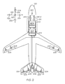
- FIG. 2 is a schematic depicting portions of an exemplary flight control surface actuation system according one embodiment of the present invention.
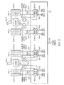
- FIG. 3 is a functional block diagram of the flight control surface actuation system of FIG. 2 , depicting certain portions thereof in slightly more detail.
- the aircraft 100 includes first and second horizontal stabilizers 101-1 and 101-2, respectively, a vertical stabilizer 103, and first and second wings 105-1 and 105-2, respectively.
- An elevator 102 is disposed on each horizontal stabilizer 101-1, 101-2
- a rudder 104 is disposed on the vertical stabilizer 103
- an aileron 106 is disposed on each wing 105-1, 105-2.
- a plurality of flaps 108, slats 112, and spoilers 114 are disposed on each wing 105-1, 105-2.
- the elevators 102, the rudder 104, and the ailerons 106 are typically referred to as the primary flight control surfaces, and the flaps 108, the slats 112, and the spoilers 114 are typically referred to as the secondary flight control surfaces.
- the primary flight control surfaces 102-106 control aircraft movements about the aircraft pitch, yaw, and roll axes.
- the elevators 102 are used to control aircraft movement about the pitch axis
- the rudder 104 is used to control aircraft movement about the yaw axis
- the ailerons 106 control aircraft movement about the roll axis. It is noted, however, that aircraft movement about the yaw axis can also be achieved by varying the thrust levels from the engines on opposing sides of the aircraft 100.
- the secondary control surfaces 108-114 influence the lift and drag of the aircraft 100.
- the flaps 108 and slats 112 may be moved from retracted positions to extended positions. In the extended position, the flaps 108 increase both lift and drag, and enable the aircraft 100 to descend at a lower airspeed, and also enable the aircraft 100 get airborne over a shorter distance.
- the slats 112, in the extended position increase lift, and are typically used in conjunction with the flaps 108.
- the spoilers 114 reduce lift and when moved from retracted positions to extended positions, which is typically done during aircraft landing operations, may be used as air brakes to assist in slowing the aircraft 100.
- the flight control surfaces 102-114 are moved to commanded positions via a flight control surface actuation system 200, an exemplary embodiment of which is shown in FIG. 2 .
- the flight control surface actuation system 200 includes flight controls 202, a plurality of primary flight control surface actuators, which include elevator actuators 204, rudder actuators 206, and aileron actuators 208.
- the system 200 may be implemented with a plurality of flight controls 202. However, for ease of description and illustration, only a single, multi-channel control 202 is depicted. It will additionally be appreciated that one or more functions of the flight controls 202 could be implemented using a plurality of devices.
- the flight control surface actuation system 200 additionally includes a plurality of secondary control surface actuators, such as flap actuators, slat actuators, and spoiler actuators.
- secondary control surface actuators such as flap actuators, slat actuators, and spoiler actuators.
- the operation of the secondary flight control surfaces 108-114 and the associated actuators is not needed to fully describe and enable the present invention.
- the secondary flight control surfaces and actuators are not depicted in FIG. 2 , nor are these devices further described.
- controls for the rudder 104 and non-illustrated aircraft brakes are also not included in FIGS. 2 and 3 for clarity and ease of description. Nonetheless, it will be appreciated that the invention may be applied to rudder and brakes controls in a similar fashion.
- the flight control surface actuation system 200 may additionally be implemented using various numbers and types of primary flight control surface actuators 204-208.
- the number and type of primary flight control surface actuators 204-208 per primary flight control surface 102-106 may be varied. In the depicted embodiment, however, the system 200 is implemented such that two primary flight control surface actuators 204-208 are coupled to each primary flight control surface 102-106.
- each of the primary flight control surface actuators 204-208 are typically a linear-type actuator, such as, for example, a ballscrew actuator or hydraulic cylinder. It will be appreciated that this number and type of primary flight control surface actuators 204-208 are merely exemplary of a particular embodiment, and that other numbers and types of actuators 204-208 could also be used.
- the flight controls 202 are configured to receive aircraft flight control surface position commands from one or more input control mechanisms.
- the system 200 includes two user interfaces, a pilot user interface 210-1 and a co-pilot user interface 210-2, and one or more motor controls 212.
- the pilot 210-1 and co-pilot 210-2 user interfaces are both implemented as active user interfaces. It will be appreciated that in some embodiments the system 200 could be implemented with more or less than this number of user interfaces 210.
- the user interface 210 (or user interfaces) could be implemented as rudder/brake pedals or, if the aircraft is of the rotary-wing type, a cyclic and/or collective.
- each flight control 202 and each motor control 212 could be integrated into a single control circuit 215, as depicted in phantom in FIG. 2 .
- the motor control 212 in response to position and/or force signals supplied from one or both user interfaces 210, supplies flight control surface position signals to the flight control(s) 202.
- the flight control(s) 202 in response to the flight control surface position signals, supplies power to the appropriate primary flight control surface actuators 204-208, to move the appropriate primary flight control surfaces 102-106 to positions that will cause the aircraft 100 to implement the commanded maneuver. As depicted in phantom in FIG.
- the system 200 can be configured such that one or more signals from the user interfaces 210, such as the just-mentioned force and/or position signals, are supplied directly to the flight control(s) 202, or are supplied to one or more aircraft data buses for communication to the flight control(s) 202.
- one or more signals from the user interfaces 210 such as the just-mentioned force and/or position signals, are supplied directly to the flight control(s) 202, or are supplied to one or more aircraft data buses for communication to the flight control(s) 202.
- FIG. 3 is also a functional block diagram of the flight control surface actuation system 200 depicting portions thereof in slightly more detail, it may be seen that the user interfaces 210 are each coupled to a suitable multiple degree-of-freedom assembly 302 (e.g., 302-1, 302-2), and are each configured to move, in response to input from either a pilot or a co-pilot, to a control position in a first direction or a second direction.
- a suitable multiple degree-of-freedom assembly 302 e.g., 302-1, 302-2
- the configuration of the flight control sticks 210 may vary, in the depicted fixed-wing embodiment, and with quick reference to FIG.
- each user interface 210 is configured to rotate, from a null position 220 to a control position, about two perpendicular rotational axes, which in the depicted fixed wing embodiment are a pitch axis 222 and a roll axis 224. More specifically, if the pilot or co-pilot moves the flight control stick 210 in a forward direction 226 or an aft direction 228, to thereby control aircraft pitch, the user interface 210 rotates about the pitch axis 222. Similarly, if the pilot or co-pilot moves the user interface 210 in a port direction 232 or a starboard direction 234, to thereby control aircraft roll, the user interface 210 rotates about the roll axis 224.
- the user interface 210 may be moved in a combined forward-port direction, a combined forward-starboard direction, a combined aft-port direction, or a combined aft-starboard direction, and back to or through the null position 220, to thereby implement a combined aircraft pitch and roll maneuver.
- user interface force signals 304 and user interface position signals 306 are supplied from the pilot 210-1 and co-pilot 210-2 user interfaces to the motor control 212, the flight control(s) 202, or both.
- the user interface force signals 304 are representative of the force applied to the respective user interfaces 210, and are supplied by user interface force sensors 308 that are coupled to each user interface 210.
- the user interface position signals 306 are representative of the respective user interface positions, and are supplied by user interface position sensors 310.
- two user interface force sensors 308 e.g., 308-1, 302-2
- two user interface position sensors 310 e.g., 310-1, 310-2
- user interface force 308 and/or position sensors 310 may vary. It will additionally be appreciated that the user interface force 308 and position 310 sensors may be implemented using any one of numerous types of force sensors and/or position sensors.
- the user interface force sensors 308 may be implemented using strain gage sensors, piezoelectric sensors, semiconductor sensors, or optical sensors, just to name a few
- the user interface position sensors 310 may be implemented using absolute inceptor position sensors such as RVDTs, LVDTs, potentiometers, or optical sensors, just to name a few.
- the user interface position sensor 310 may be configured to sense either the position of the user interface 210 or the rotational position of another component to which the user interface 210 is coupled, such as the motor 318. If the user interface position sensor 310 is configured to sense the position of, for example, the motor 318 using sensors such as a resolver or an encoder, to name just a few, then user interface position may be derived by integrating the sensed motor position. One or more additional position sensors (not depicted) may be included if user interface position is derived from motor position to, for example, initialize the motor position integrator. It will be further appreciated that the motor position integrator could also be initialized using a touch stop method.
- At least one of the user interface force sensors 308-1 (308-2) associated with each user interface 210 is configured to sense a vector component of the input force supplied to the user interface 210 that results in user interface rotation about the pitch axis 222
- another user interface force sensor 308-2 (308-1) associated with each user interface 210 is configured to sense a vector component of the input force supplied to the user interface 210 that results in user interface rotation about the roll axis 224.
- one of the user interface position sensors 310-1 (310-2) associated with each user interface 210 is configured to supply user interface position signals representative of a vector component of the user interface position that lies along the pitch axis 222
- another user interface position sensor 308-2 (308-1) associated with each user interface 210 is configured to supply user interface position signals representative a vector component of the user interface position that lies along the roll axis 224.
- the user interface force signals 304 and the user interface position signals 306 are each supplied to the motor control 212.
- the motor control 212 upon receipt of the user interface force signals 304 and the user interface position signals 306, supplies flight control surface position commands 312 to the flight control(s) 202, which in turn supplies power to the appropriate primary flight control surface actuators 204-208, to move the appropriate primary flight control surfaces 102-106 to the appropriate positions, to thereby implement a desired maneuver.
- the flight control(s) 202 upon receipt of the user interface force signals 304 and the user interface position signals 306, supplies flight control surface position commands 312 to the flight control(s) 202, which in turn supplies power to the appropriate primary flight control surface actuators 204-208, to move the appropriate primary flight control surfaces 102-106 to the appropriate positions, to thereby implement a desired maneuver.
- the flight control(s) 202 may receive the user interface force signals 304 and/or user interface position signals 306 directly from the user interface force sensors 308 and/or user interface position sensors 310 and, in response, supply power to the appropriate primary flight control surface actuators 204-208, to move the appropriate primary flight control surfaces 102-106 to the appropriate positions.
- the motor control 212 includes a plurality of motor controls 314 (e.g., 314-1, 314-2, 314-3, 314-4).
- the motor control 212 includes two pilot user interface motor controls 314-1, 314-2 and two co-pilot user interface motor controls 314-3, 314-4.
- the pilot user interface motor controls 314-1, 314-2 each control motor current to one of the pilot user interface motors 316-1, 316-2
- the co-pilot user interface motor controls 314-3, 314-4 each control motor current to one of the co-pilot user interface motors 316-3, 316-4.
- the motors 316 which are each coupled to one of the user interfaces 210, typically via non-illustrated gear sets, are each operable, upon receipt of the motor current, to supply user interface feedback force to the associated user interface 210.
- the user interfaces 210 in response to the user interface feedback force supplied from the associated motors 316, supply haptic feedback to the pilot or co-pilot, as the case may be.
- the motors 316 are each implemented using permanent magnet brushless machines. As such, current feedback and commutation signals 318 associated with each motor 316 are supplied to that motor's associated motor control 314.
- the pilot user interface motor controls 314-1, 314-2 additionally control the motor current supplied to the pilot user interface motors 316-1, 316-2 based, at least in part, on the respective co-pilot user interface force signals 304 or the respective co-pilot user interface position signals 304.
- co-pilot user interface motor controls 314 -3, 314-4 additionally control the motor current supplied to the co-pilot user interface motors 316-1, 316-2 based, at least in part, on the respective pilot user interface force signals 304 or the respective pilot user interface position signals 306.
- each motor control 314 may additionally control the motor current to its respective motor 316 based, at least further in part, on various other parameters including, for example, the slew rate of the user interfaces 210, and various aircraft and control surface conditions.
- each motor control 314 controls the motor current to its respective motor 316 based, at least in part, on the pilot and co-pilot user interface force signals 304 supplied thereto or the respective pilot and co-pilot user interface position signals 306 supplied thereto.
- each motor control 314 is configured, during normal system operation, to control the motor current to its respective motor 316 based, at least in part, on the pilot and co-pilot user interface force signals 304 that are supplied thereto.
- the motor control 314 will continue to control the motor current to its respective motor 316 based, at least in part, the remaining user interface force signal 304 (if only one is not received) and additionally on either or both the pilot and co-pilot user interface position signals 306.
- pilot user interface motor control 314-1, 314-2 will continue to control the motor current to its respective pilot user interface motor 316-1, 316-2 based, at least in part, on the co-pilot user interface force signal 304 and additionally on the pilot user interface position signal 306. If, however, a pilot user interface motor control 314-1, 314-2 does not receive both the pilot and co-pilot user interface force signals 304, then that pilot user interface motor control 314-1, 314-2 will control the motor current to its respective pilot user interface motor 316-1, 316-2 based, at least in part, on the pilot and co-pilot user interface position signals 306.
- a co-pilot user interface motor control 314-3, 314-4 does not receive the co-pilot user interface force signal 304 only, then that co-pilot user interface motor control 314-3, 314-4 will continue to control the motor current to its respective co-pilot user interface motor 316-3, 316-4 based, at least in part, on the pilot user interface force signal 304 and additionally on the co-pilot user interface position signal 306.
- a co-pilot user interface motor control 314-3, 314-4 does not receive both the pilot and co-pilot user interface force signals 304, then that co-pilot user interface motor control 314-3, 314-4 will control the motor current to its respective co-pilot user interface motor 316-3, 316-4 based, at least in part, on the pilot and co-pilot user interface position signals 306.
- each motor control 314 is configured, during normal system operation, to control the motor current to its respective motor 316 based, at least in part, on the pilot and co-pilot user interface position signals 306 that are supplied thereto, rather than on the pilot and co-pilot user interface force signals 304.
- This embodiment functions much like the above-described embodiment, in that if one or both of the user interface position signals 306 is not received by a motor control 314 due to, for example, one or more failed or otherwise inoperable user interface position sensors 310, then the affected motor control(s) 314 will continue to control the motor current to the respective motor(s) 316 based, at least in part, the remaining user interface position signal 306 (if only one is not received) and additionally on either or both the pilot and co-pilot user interface force signals 304.
- linking is implemented using both force and position data, so that the unavailability of all or portions of either of these data is accommodated passively.
- linking is implemented using either force or position data, and if the force or position data become unavailable then position or force data, respectively, are used.
Landscapes
- Engineering & Computer Science (AREA)
- Automation & Control Theory (AREA)
- Aviation & Aerospace Engineering (AREA)
- User Interface Of Digital Computer (AREA)
- Mechanical Control Devices (AREA)
Claims (9)
- Steuersystem (200) einer aktiven Anwenderschnittstelle (210), das Folgendes umfasst:eine Pilotenanwenderschnittstelle (210), die konfiguriert ist, eine Eingangskraft aufzunehmen und sich nach dem Aufnehmen der Eingangskraft zu einer Steuerposition zu bewegen;einen Pilotenanwenderschnittstellenkraftsensor (308), der konfiguriert ist, die Eingangskraft abzufühlen, die auf die Pilotenanwenderschnittstelle (210) ausgeübt wird, und die betreibbar ist, um ein dafür repräsentatives Pilotenanwenderschnittstellenkraftsignal (304) zu liefern ist;einen Pilotenanwenderschnittstellenpositionssensor (310), der betreibbar ist, um ein Pilotenanwenderschnittstellenpositionssignal (306), das repräsentativ für die Pilotenanwenderschnittstellenposition (220) ist, zu liefern;einen Pilotenanwenderschnittstellenmotor (316), der mit der Pilotenanwenderschnittstelle (210) gekoppelt ist, wobei der Pilotenanwenderschnittstellenmotor (316) ferner gekoppelt ist, um Motorstrom aufzunehmen, und betreibbar ist, um nach dem Aufnehmen des Motorstroms eine Pilotenanwenderschnittstellenrückkopplungskraft zu der Pilotenanwenderschnittstelle (210) zu liefern; undeine Pilotenanwenderschnittstellenmotorsteuerung (314), die gekoppelt ist, um das Pilotenanwenderschnittstellenkraftsignal (304) und das Pilotenanwenderschnittstellenpositionssignal (306) zu empfangen, und die betreibbar ist, um selektiv Motorstrom zu dem Pilotenanwenderschnittstellenmotor (316) zu steuern basierend auf entweder (i) dem Pilotenanwenderschnittstellenkraftsignal (304) oder (ii) dem Pilotenanwenderschnittstellenpositionssignal (306), wobei die Pilotenanwenderschnittstellenmotorsteuerung (314)selektiv den Motorstrom zu dem Pilotenanwenderschnittstellenmotor (316) steuert basierend auf:dem Pilotenanwenderschnittstellenkraftsignal (304) wenigstens dann, wenn das Pilotenanwenderschnittstellenpositionssignal (306) nicht von der Pilotenanwenderschnittstellenmotorsteuerung (314) empfangen wird; unddem Pilotenanwenderschnittstellenpositionssignal (306) wenigstens dann, wenn das Pilotenanwenderschnittstellenkraftsignal (304) nicht von der Pilotenanwenderschnittstellenmotorsteuerung (314) empfangen wird.
- System nach Anspruch 1, wobei:die Pilotenanwenderschnittstelle (210) konfiguriert ist, sich von einer Null-Position (220) um eine erste Drehachse und eine zweite Drehachse zu drehen, wobei die zweite Drehachse senkrecht zur ersten Drehachse ist;die Pilotenanwenderschnittstelle (210) auf die ausgeübte Eingangskraft reagiert, um sich von der Null-Position (220) zu der Steuerposition um die erste und/oder die zweite Drehachse zu drehen;der Pilotenanwenderschnittstellenkraftsensor konfiguriert ist, eine Vektorkomponente der Eingangskraft, die auf die Pilotenanwenderschnittstelle (210) ausgeübt wird, abzufühlen, die zur Pilotenanwenderschnittstellendrehung um die erste Drehachse führt;der Pilotenanwenderschnittstellenpositionssensor (310) konfiguriert ist, ein Signal zu liefern, das repräsentativ ist für eine Vektorkomponente der Steuerposition, die längs der zweiten Drehachse liegt; undder Pilotenanwenderschnittstellenmotor (316) konfiguriert ist, nach dem Aufnehmen von Motorstrom die Pilotenanwenderschnittstellenrückkopplungskraft auf die Pilotenanwenderschnittstelle (210) um die erste Drehachse auszuüben.
- System nach Anspruch 2, das ferner Folgendes umfasst:einen zweiten Pilotenanwenderschnittstellenkraftsensor, der konfiguriert ist, eine Vektorkomponente der Eingangskraft, die auf die Pilotenanwenderschnittstelle (210) ausgeübt wird, abzufühlen, die zu einer Drehung der Pilotenanwenderschnittstelle (210) um die zweite Drehachse führt, und der betreibbar ist, ein zweites dafür repräsentatives Pilotenanwenderschnittstellenkraftsignal (304) zu liefern;einen zweiten Pilotenanwenderschnittstellenpositionssensor (310), der betreibbar ist, um ein zweites Pilotenanwenderschnittstellenpositionssignal (306) zu liefern, das repräsentativ ist für eine Vektorkomponente der Steuerposition, die längs der ersten Drehachse liegt;einen zweiten Pilotenanwenderschnittstellenmotor (316), der mit der Pilotenanwenderschnittstelle (210) gekoppelt ist, wobei der zweite Pilotenanwenderschnittstellenmotor (316) ferner gekoppelt ist, um Motorstrom aufzunehmen, und betreibbar ist, um nach dessen Aufnehmen eine zweite Pilotenanwenderschnittstellenrückkopplungskraft um die zweite Drehachse auf die Pilotenanwenderschnittstelle (210) auszuüben; undeine zweite Pilotenanwenderschnittstellenmotorsteuerung (314), die gekoppelt ist, um das zweite Pilotenanwenderschnittstellenkraftsignal (304) und das zweite Pilotenanwenderschnittstellenpositionssignal (306) zu empfangen, und betreibbar ist, um selektiv den Motorstrom zu dem Copilotenanwenderschnittstellenmotor (316) zu steuern basierend auf entweder (i) dem zweiten Pilotenanwenderschnittstellenkraftsignal (304) oder (ii) dem zweiten Pilotenanwenderschnittstellenpositionssignal (306),wobei die zweite Pilotenanwenderschnittstellenmotorsteuerung (314) selektiv Motorstrom zu dem zweiten Pilotenanwenderschnittstellenmotor (316) steuert, basierend auf:dem zweiten Pilotenanwenderschnittstellenkraftsignal (304) wenigstens dann, wenn das zweite Pilotenanwenderschnittstellenpositionssignal (306) nicht von der zweiten Pilotenanwenderschnittstellenmotorsteuerung (314) empfangen wird; unddem zweiten Pilotenanwenderschnittstellenpositionssignal (306) wenigstens dann, wenn das zweite Pilotenanwenderschnittstellenkraftsignal (304) nicht von der zweiten Pilotenanwenderschnittstellenmotorsteuerung (314) empfangen wird.
- System nach Anspruch 1, das ferner Folgendes umfasst:eine Copilotenanwenderschnittstelle (210), die konfiguriert ist, eine Eingangskraft aufzunehmen und sich nach dem Aufnehmen der Eingangskraft zu einer Position zu bewegen;einen Copilotenanwenderschnittstellenkraftsensor (308), der konfiguriert ist, die Eingangskraft, die auf die Copilotenanwenderschnittstelle (210) ausgeübt wird, abzufühlen, und der betreibbar ist, um ein dafür repräsentatives Copilotenanwenderschnittstellenkraftsignal (304) zu liefern;einen Copilotenanwenderschnittstellenpositionssensor (310), der betreibbar ist, um ein Copilotenanwenderschnittstellenpositionssignal (306), das für die Copilotenanwenderschnittstellenposition (220) repräsentativ ist, zu liefern.
- System nach Anspruch 4, wobei:eine Pilotenanwenderschnittstellenmotorsteuerung (314) ferner gekoppelt ist, um das Copilotenanwenderschnittstellenkraftsignal (304) und das Copilotenanwenderschnittstellenpositionssignal (306) zu empfangen, und ferner betreibbar ist, um selektiv den Motorstrom zu dem Pilotenanwenderschnittstellenmotor (316) zu steuern basierend auf entweder (i) dem Copilotenanwenderschnittstellenkraftsignal (304) oder (ii) dem Copilotenanwenderschnittstellenpositionssignal (306); unddie Pilotenanwenderschnittstellenmotorsteuerung (314) ferner selektiv den Motorstrom zu dem Pilotenanwenderschnittstellenmotor (316) steuert, basierend auf:dem Copilotenanwenderschnittstellenkraftsignal (304) wenigstens dann, wenn das Copilotenanwenderschnittstellenpositionssignal (306) nicht von der Pilotenanwenderschnittstellenmotorsteuerung (314) empfangen wird; unddem Copilotenanwenderschnittstellenpositionssignal (304) wenigstens dann, wenn das Copilotenanwenderschnittstellenkraftsignal (306) nicht von der Pilotenanwenderschnittstellenmotorsteuerung (314) empfangen wird.
- System nach Anspruch 5, das ferner Folgendes umfasst:einen Copilotenanwenderschnittstellenmotor (316), der mit der Copilotenanwenderschnittstelle (210) gekoppelt ist, wobei der Copilotenanwenderschnittstellenmotor (316) ferner gekoppelt ist, um Motorstrom aufzunehmen, und betreibbar ist, um nach dessen Aufnehmen eine Copilotenanwenderschnittstellenrückkopplungskraft auf die Copilotenanwenderschnittstelle (210) auszuüben; undeine Copilotenanwenderschnittstellenmotorsteuerung (314), die gekoppelt ist, um das Copilotenanwenderschnittstellenkraftsignal (304) und das Copilotenanwenderschnittstellenpositionssignal (306) zu empfangen, und betreibbar ist, um selektiv den Motorstrom zu dem Copilotenanwenderschnittstellenmotor (316) zu steuern basierend auf entweder (i) dem Copilotenanwenderschnittstellenkraftsignal (304) oder (ii) dem Copilotenanwenderschnittstellenpositionssignal (306).
- System nach Anspruch 6, wobei:die Copilotenanwenderschnittstellenmotorsteuerung (314) selektiv Motorstrom zu dem Copilotenanwenderschnittstellenmotor (316) steuert basierend auf (i) dem Copilotenanwenderschnittstellenkraftsignal (304) wenigstens dann, wenn das Copilotenanwenderschnittstellenpositionssignal (306) nicht von der Copilotenanwenderschnittstellenmotorsteuerung (314) empfangen wird, und (ii) dem Copilotenanwenderschnittstellenpositionssignal (306) wenigstens dann, wenn das Copilotenanwenderschnittstellenkraftsignal (304) nicht von der Copilotenanwenderschnittstellenmotorsteuerung (314) empfangen wird;die Copilotenanwenderschnittstellenmotorsteuerung (314) ferner gekoppelt ist, um das Pilotenanwenderschnittstellenkraftsignal (304) und das Pilotenanwenderschnittstellenpositionssignal (306) zu empfangen, und ferner betreibbar ist, um selektiv den Motorstrom zu dem Copilotenanwenderschnittstellenmotor (316) zu steuern basierend auf entweder (i) dem Pilotenanwenderschnittstellenkraftsignal (304) oder (ii) dem Pilotenanwenderschnittstellenpositionssignal (306);die Copilotenanwenderschnittstellenmotorsteuerung (314) ferner selektiv Motorstrom zu dem Copilotenanwenderschnittstellenmotor (316) steuert basierend auf (i) dem Pilotenanwenderschnittstellenkraftsignal (304) wenigstens dann, wenn das Pilotenanwenderschnittstellenpositionssignal (306) nicht von der Copilotenanwenderschnittstellenmotorsteuerung (314) empfangen wird, und (ii) dem Pilotenanwenderschnittstellenpositionssignal (306) wenigstens dann, wenn das Pilotenanwenderschnittstellenkraftsignal (304) nicht von der Copilotenanwenderschnittstellenmotorsteuerung (314) empfangen wird.
- System nach Anspruch 7, wobei:die Copilotenanwenderschnittstelle (210) konfiguriert ist, sich von einer Null-Position (220) um eine erste Drehachse und um eine zweite Drehachse zu drehen, wobei die zweite Drehachse senkrecht zur ersten Drehachse ist;die Copilotenanwenderschnittstelle (210) auf die ausgeübte Eingangskraft reagiert, um sich von der Null-Position (220) zu der Steuerposition um die erste und/oder die zweite Drehachse zu drehen;der Copilotenanwenderschnittstellenkraftsensor (304) konfiguriert ist, eine Vektorkomponente der Eingangskraft, die auf die Copilotenanwenderschnittstelle (210) ausgeübt wird, abzufühlen, die zur Drehung der Copilotenanwenderschnittstelle um die erste Drehachse führt;der Copilotenanwenderschnittstellenpositionssensor betreibbar ist, ein Copilotenanwenderschnittstellenpositionssignal (306) zu liefern, das für eine Vektorkomponente der Steuerposition, die längs der zweiten Drehachse liegt, repräsentativ ist; undder Copilotenanwenderschnittstellenmotor (316) konfiguriert ist, nach dem Aufnehmen von Motorstrom die Rückkopplungskraft der Copilotenanwenderschnittstelle (210) auf die Copilotenanwenderschnittstelle um die erste Drehachse auszuüben.
- System nach Anspruch 8, das ferner Folgendes umfasst:einen zweiten Copilotenanwenderschnittstellenkraftsensor (304), der konfiguriert ist, eine Vektorkomponente der Eingangskraft, die auf die Copilotenanwenderschnittstelle (210) ausgeübt wird, abzufühlen, die zu einer Drehung der Copilotenanwenderschnittstelle um die zweite Drehachse führt, und der betreibbar ist, um ein dafür repräsentatives zweites Copilotenanwenderschnittstellenkraftsignal (304) zu liefern;einen zweiten Copilotenanwenderschnittstellenpositionssensor (310), der betreibbar ist, um ein zweites Copilotenanwenderschnittstellenpositionssignal (306) zu liefern, das für eine Vektorkomponente der Steuerposition, die längs der ersten Drehachse liegt, repräsentativ ist; undeinen zweiten Copilotenanwenderschnittstellenmotor (316), der mit der Copilotenanwenderschnittstelle (210) gekoppelt ist, wobei der zweite Copilotenanwenderschnittstellenmotor (316) ferner gekoppelt ist, um Motorstrom aufzunehmen, und betreibbar ist, um nach dessen Aufnehmen eine zweite Copilotenanwenderschnittstellenrückkopplungskraft auf die zweite Drehachse zu der Copilotenanwenderschnittstelle (210) auszuüben; undeine zweite Copilotenanwenderschnittstellenmotorsteuerung (314), die gekoppelt ist, um das zweite Copilotenanwenderschnittstellenkraftsignal (304) und das zweite Copilotenanwenderschnittstellenpositionssignal (306) zu empfangen, und betreibbar ist, um selektiv den Motorstrom zu dem zweiten Copilotenanwenderschnittstellenmotor (316) zu steuern basierend auf entweder (i) dem zweiten Copilotenanwenderschnittstellenkraftsignal (304) oder (ii) dem zweiten Copilotenanwenderschnittstellenpositionssignal (306),wobei die zweite Copilotenanwenderschnittstellenmotorsteuerung (314) selektiv Motorstrom zu dem zweiten Copilotenanwenderschnittstellenmotor (316) steuert, basierend auf:dem zweiten Copilotenanwenderschnittstellenkraftsignal (304) wenigstens dann, wenn das zweite Copilotenanwenderschnittstellenpositionssignal (306) nicht von der zweiten Copilotenanwenderschnittstellenmotorsteuerung (314) empfangen wird; unddem zweiten Copilotenanwenderschnittstellenpositionssignal (306) wenigstens dann, wenn das zweite Copilotenanwenderschnittstellenkraftsignal (304) nicht von der zweiten Copilotenanwenderschnittstellenmotorsteuerung (314) empfangen wird.
Applications Claiming Priority (1)
| Application Number | Priority Date | Filing Date | Title |
|---|---|---|---|
| US11/938,581 US8078340B2 (en) | 2007-11-12 | 2007-11-12 | Active user interface haptic feedback and linking control system using either force or position data |
Publications (3)
| Publication Number | Publication Date |
|---|---|
| EP2058227A2 EP2058227A2 (de) | 2009-05-13 |
| EP2058227A3 EP2058227A3 (de) | 2012-12-26 |
| EP2058227B1 true EP2058227B1 (de) | 2013-09-04 |
Family
ID=40445255
Family Applications (1)
| Application Number | Title | Priority Date | Filing Date |
|---|---|---|---|
| EP08168790.7A Expired - Fee Related EP2058227B1 (de) | 2007-11-12 | 2008-11-10 | Steuerungsystem einer aktiven Benutzerschnittstelle für haptische Rückkopplung und Vernetzung unter Verwendung entweder von Kraft- oder Positionsdaten |
Country Status (2)
| Country | Link |
|---|---|
| US (1) | US8078340B2 (de) |
| EP (1) | EP2058227B1 (de) |
Families Citing this family (22)
| Publication number | Priority date | Publication date | Assignee | Title |
|---|---|---|---|---|
| US9340278B2 (en) * | 2006-05-17 | 2016-05-17 | Textron Innovations, Inc. | Flight control system |
| FR2952447B1 (fr) * | 2009-11-06 | 2012-08-17 | Ratier Figeac Soc | Dispositif de controle electronique de fonctionnement d'un organe de pilotage a surveillance croisee, dispositif de pilotage et aeronef |
| US9405312B2 (en) * | 2010-07-28 | 2016-08-02 | Woodward Mpc, Inc. | Active control column with manually activated reversion to passive control column |
| US9051045B2 (en) | 2010-07-28 | 2015-06-09 | Woodward Mpc, Inc. | Indirect drive active control column |
| US8534599B2 (en) * | 2011-03-31 | 2013-09-17 | Hamilton Sundstrand Corporation | Redundant two stage electro-hydraulic servo actuator control |
| SI2737621T1 (sl) * | 2011-07-26 | 2022-10-28 | Moog Inc. | Vpenjalni sistem z električnim motorjem |
| US9102400B2 (en) * | 2011-10-21 | 2015-08-11 | Sikorsky Aircraft Corporation | Methods and systems for providing constant-feel, multi-axis tactile cues |
| US9126676B2 (en) | 2011-10-28 | 2015-09-08 | Woodward Mpc, Inc. | Compact two axis gimbal for control stick |
| US9124198B2 (en) * | 2013-04-08 | 2015-09-01 | Hamilton Sundstrand Corporation | Multiplexed motor controller |
| EP3016857B1 (de) * | 2013-07-01 | 2017-04-12 | BAE Systems PLC | Steuerorgan und verfahren zum betreiben eines steuerorgans |
| US9096325B2 (en) | 2013-11-18 | 2015-08-04 | Bell Helicopter Textron Inc. | Fly-by-wire engine power control system |
| FR3016488B1 (fr) * | 2014-01-14 | 2016-02-12 | Ratier Figeac Soc | Procede et dispositif de commande d'un levier de manœuvre d'un vehicule |
| ES2580252B2 (es) * | 2015-10-05 | 2017-03-17 | Defensya Ingeniería Internacional, S.L. | Dispositivo de realidad aumentada haptico para facilitar las acciones sobre una pértiga de repostaje en vuelo |
| US10074245B2 (en) | 2017-01-10 | 2018-09-11 | Woodward, Inc. | Force feel using a brushless DC motor |
| US11021244B2 (en) * | 2017-03-06 | 2021-06-01 | Textron Innovations Inc. | Collective control stick mounted throttle control assembly |
| EP3882134B1 (de) * | 2020-03-20 | 2024-09-25 | Ratier-Figeac SAS | Cockpitsteuerorgansystem |
| DE102020208678A1 (de) | 2020-07-10 | 2022-01-13 | Robert Bosch Gesellschaft mit beschränkter Haftung | Verfahren zum Betrieb einer Bedienvorrichtung, insbesondere zur Steuerung einer Längs- und/oder Querbewegung eines Fahrzeugs |
| EP3998198B1 (de) | 2021-02-19 | 2024-07-03 | Lilium eAircraft GmbH | Flugzeugsteuerorganvorrichtung und flugsteuerungssystem eines flugzeugs |
| US12162603B2 (en) * | 2021-10-26 | 2024-12-10 | Honeywell International Inc. | System and method to enhance in-flight controlled rest for flight crew |
| EP4406832A1 (de) * | 2023-01-25 | 2024-07-31 | BAE SYSTEMS plc | Aktive drosselanordnung und steuersystem |
| KR20250140542A (ko) * | 2023-01-25 | 2025-09-25 | 배 시스템즈 피엘시 | 능동 스로틀 장치 및 제어 시스템 |
| GB202301046D0 (en) * | 2023-01-25 | 2023-03-08 | Bae Systems Plc | Active throttle arrangement and control system |
Family Cites Families (19)
| Publication number | Priority date | Publication date | Assignee | Title |
|---|---|---|---|---|
| US5264768A (en) * | 1992-10-06 | 1993-11-23 | Honeywell, Inc. | Active hand controller feedback loop |
| US5291113A (en) * | 1992-10-06 | 1994-03-01 | Honeywell Inc. | Servo coupled hand controllers |
| US5370535A (en) * | 1992-11-16 | 1994-12-06 | Cae-Link Corporation | Apparatus and method for primary control loading for vehicle simulation |
| US5456428A (en) * | 1993-07-21 | 1995-10-10 | Honeywell Inc. | Mechanically linked active sidesticks |
| US5489830A (en) * | 1994-09-09 | 1996-02-06 | Mcdonnell Douglas Corporation | Control system with loadfeel and backdrive |
| FR2728537A1 (fr) * | 1994-12-21 | 1996-06-28 | Eurocopter France | Dispositif pour l'actionnement d'un organe commande pour un aeronef, tel que notamment un helicoptere, a commandes de vol electriques |
| US5694014A (en) * | 1995-08-22 | 1997-12-02 | Honeywell Inc. | Active hand controller redundancy and architecture |
| FR2754515B1 (fr) * | 1996-10-14 | 1998-12-24 | Aerospatiale | Dispositif d'aide au pilotage sur un aeronef a commande de vol electrique |
| US6459228B1 (en) * | 2001-03-22 | 2002-10-01 | Mpc Products Corporation | Dual input servo coupled control sticks |
| WO2003040844A2 (en) * | 2001-11-06 | 2003-05-15 | Bombardier Inc. | Apparatus for controlling a joystick having force-feedback |
| US6679458B2 (en) * | 2002-06-10 | 2004-01-20 | The Boeing Company | Split detent tactile cueing vehicle control system |
| US20040078121A1 (en) * | 2002-10-22 | 2004-04-22 | Cartmell Daniel H. | Control system and method with multiple linked inputs |
| US7108232B2 (en) * | 2004-02-05 | 2006-09-19 | Hoh Roger H | Helicopter force-feel and stability augmentation system with parallel servo-actuator |
| FR2888009B1 (fr) * | 2005-06-30 | 2007-09-07 | Dassault Aviat | Dispositif de commande comportant deux manches couples pour permettre de placer des organes commandes dans des positions souhaitees |
| US7667064B2 (en) * | 2005-12-14 | 2010-02-23 | Exxonmobil Chemical Patents Inc. | Halogen substituted metallocene compounds for olefin polymerization |
| JP2009523657A (ja) * | 2006-01-17 | 2009-06-25 | ガルフストリーム・エアロスペース・コーポレイション | 統合バックアップ制御システム用のシステムおよび方法 |
| US7658349B2 (en) * | 2006-10-26 | 2010-02-09 | Honeywell International Inc. | Pilot flight control stick haptic feedback system and method |
| US7759894B2 (en) * | 2006-10-26 | 2010-07-20 | Honeywell International Inc. | Cogless motor driven active user interface haptic feedback system |
| US20080156939A1 (en) * | 2007-01-03 | 2008-07-03 | Honeywell International, Inc. | Active pilot flight control stick system with passive electromagnetic feedback |
-
2007
- 2007-11-12 US US11/938,581 patent/US8078340B2/en not_active Expired - Fee Related
-
2008
- 2008-11-10 EP EP08168790.7A patent/EP2058227B1/de not_active Expired - Fee Related
Also Published As
| Publication number | Publication date |
|---|---|
| EP2058227A3 (de) | 2012-12-26 |
| US8078340B2 (en) | 2011-12-13 |
| US20090125166A1 (en) | 2009-05-14 |
| EP2058227A2 (de) | 2009-05-13 |
Similar Documents
| Publication | Publication Date | Title |
|---|---|---|
| EP2058227B1 (de) | Steuerungsystem einer aktiven Benutzerschnittstelle für haptische Rückkopplung und Vernetzung unter Verwendung entweder von Kraft- oder Positionsdaten | |
| EP2076432B1 (de) | Haptisches rückkopplungssystem mit einer durch einen nutrastfreien motor angetriebenen aktiven benutzerschnittstelle | |
| EP1918196B1 (de) | System und Verfahren für ein haptisches Feedback zu einem Piloten-Steuerknüppel | |
| EP1908685B1 (de) | Motorausgeglichene, aktive Benutzerschnittstellenanordnung | |
| EP2052966B1 (de) | Geschwindigkeitsbeschränktes aktives Pilotsteuerorgansystem und Verfahren | |
| US8172174B2 (en) | Hybrid electromechanical/hydromechanical actuator and actuation control system | |
| US8080966B2 (en) | Motor control architecture for simultaneously controlling multiple motors | |
| CN114954909B (zh) | 飞行器操纵器装置以及飞行器飞行控制系统 | |
| KR101323836B1 (ko) | 항공기 내의 수동 비행 제어 시스템용 직렬 액츄에이터에 의한 비상 조종 방법 | |
| US8134328B2 (en) | Active pilot inceptor with self warm-up | |
| EP2072395A2 (de) | Eingeschränkte Befugnis und vollbefugtes fly-by-wire Flugsteuerflächen-Betätigungssteuerungssystem | |
| US20080156939A1 (en) | Active pilot flight control stick system with passive electromagnetic feedback | |
| WO2006023982A1 (en) | Aircraft flight control surface actuation system communication architecture | |
| US20070235594A1 (en) | Pilot flight control stick feedback system | |
| EP1977970A2 (de) | Passives haptisches Rückkoppelungssystem für eine Benutzerschnittstelle | |
| US8380364B2 (en) | Manual and computerized flight control system with natural feedback | |
| EP2078997A2 (de) | Mensch-Maschine-Schnittstelle mit variabler Null-Losbrechkraft | |
| CN115246476A (zh) | 驾驶位操纵机构、飞机操纵系统及其控制方法和飞机 | |
| CN109866916B (zh) | 电控制构件、旋翼飞行器和方法 |
Legal Events
| Date | Code | Title | Description |
|---|---|---|---|
| PUAI | Public reference made under article 153(3) epc to a published international application that has entered the european phase |
Free format text: ORIGINAL CODE: 0009012 |
|
| 17P | Request for examination filed |
Effective date: 20081110 |
|
| AK | Designated contracting states |
Kind code of ref document: A2 Designated state(s): AT BE BG CH CY CZ DE DK EE ES FI FR GB GR HR HU IE IS IT LI LT LU LV MC MT NL NO PL PT RO SE SI SK TR |
|
| AX | Request for extension of the european patent |
Extension state: AL BA MK RS |
|
| PUAL | Search report despatched |
Free format text: ORIGINAL CODE: 0009013 |
|
| AK | Designated contracting states |
Kind code of ref document: A3 Designated state(s): AT BE BG CH CY CZ DE DK EE ES FI FR GB GR HR HU IE IS IT LI LT LU LV MC MT NL NO PL PT RO SE SI SK TR |
|
| AX | Request for extension of the european patent |
Extension state: AL BA MK RS |
|
| RIC1 | Information provided on ipc code assigned before grant |
Ipc: B64C 13/10 20060101AFI20121122BHEP Ipc: B64C 13/50 20060101ALI20121122BHEP Ipc: G05D 1/08 20060101ALI20121122BHEP |
|
| 17Q | First examination report despatched |
Effective date: 20121210 |
|
| GRAP | Despatch of communication of intention to grant a patent |
Free format text: ORIGINAL CODE: EPIDOSNIGR1 |
|
| INTG | Intention to grant announced |
Effective date: 20130417 |
|
| GRAS | Grant fee paid |
Free format text: ORIGINAL CODE: EPIDOSNIGR3 |
|
| GRAA | (expected) grant |
Free format text: ORIGINAL CODE: 0009210 |
|
| AK | Designated contracting states |
Kind code of ref document: B1 Designated state(s): DE FR GB |
|
| AKX | Designation fees paid |
Designated state(s): DE FR GB |
|
| REG | Reference to a national code |
Ref country code: GB Ref legal event code: FG4D |
|
| REG | Reference to a national code |
Ref country code: DE Ref legal event code: R096 Ref document number: 602008027265 Country of ref document: DE Effective date: 20131031 |
|
| REG | Reference to a national code |
Ref country code: DE Ref legal event code: R097 Ref document number: 602008027265 Country of ref document: DE |
|
| PLBE | No opposition filed within time limit |
Free format text: ORIGINAL CODE: 0009261 |
|
| STAA | Information on the status of an ep patent application or granted ep patent |
Free format text: STATUS: NO OPPOSITION FILED WITHIN TIME LIMIT |
|
| 26N | No opposition filed |
Effective date: 20140605 |
|
| REG | Reference to a national code |
Ref country code: DE Ref legal event code: R097 Ref document number: 602008027265 Country of ref document: DE Effective date: 20140605 |
|
| PGFP | Annual fee paid to national office [announced via postgrant information from national office to epo] |
Ref country code: GB Payment date: 20141027 Year of fee payment: 7 Ref country code: FR Payment date: 20141027 Year of fee payment: 7 Ref country code: DE Payment date: 20141201 Year of fee payment: 7 |
|
| REG | Reference to a national code |
Ref country code: DE Ref legal event code: R119 Ref document number: 602008027265 Country of ref document: DE |
|
| GBPC | Gb: european patent ceased through non-payment of renewal fee |
Effective date: 20151110 |
|
| REG | Reference to a national code |
Ref country code: FR Ref legal event code: ST Effective date: 20160729 |
|
| PG25 | Lapsed in a contracting state [announced via postgrant information from national office to epo] |
Ref country code: DE Free format text: LAPSE BECAUSE OF NON-PAYMENT OF DUE FEES Effective date: 20160601 Ref country code: GB Free format text: LAPSE BECAUSE OF NON-PAYMENT OF DUE FEES Effective date: 20151110 |
|
| PG25 | Lapsed in a contracting state [announced via postgrant information from national office to epo] |
Ref country code: FR Free format text: LAPSE BECAUSE OF NON-PAYMENT OF DUE FEES Effective date: 20151130 |
|
| P01 | Opt-out of the competence of the unified patent court (upc) registered |
Effective date: 20230525 |