EP2058449A2 - Montageanordnung für eine Dachabdeckung - Google Patents
Montageanordnung für eine Dachabdeckung Download PDFInfo
- Publication number
- EP2058449A2 EP2058449A2 EP08253407A EP08253407A EP2058449A2 EP 2058449 A2 EP2058449 A2 EP 2058449A2 EP 08253407 A EP08253407 A EP 08253407A EP 08253407 A EP08253407 A EP 08253407A EP 2058449 A2 EP2058449 A2 EP 2058449A2
- Authority
- EP
- European Patent Office
- Prior art keywords
- fixture
- retaining
- members
- assembly
- assembly according
- Prior art date
- Legal status (The legal status is an assumption and is not a legal conclusion. Google has not performed a legal analysis and makes no representation as to the accuracy of the status listed.)
- Withdrawn
Links
Images


Classifications
-
- E—FIXED CONSTRUCTIONS
- E04—BUILDING
- E04D—ROOF COVERINGS; SKY-LIGHTS; GUTTERS; ROOF-WORKING TOOLS
- E04D13/00—Special arrangements or devices in connection with roof coverings; Protection against birds; Roof drainage ; Sky-lights
- E04D13/15—Trimming strips; Edge strips; Fascias; Expansion joints for roofs
- E04D13/155—Trimming strips; Edge strips; Fascias; Expansion joints for roofs retaining the roof sheathing
-
- E—FIXED CONSTRUCTIONS
- E04—BUILDING
- E04D—ROOF COVERINGS; SKY-LIGHTS; GUTTERS; ROOF-WORKING TOOLS
- E04D13/00—Special arrangements or devices in connection with roof coverings; Protection against birds; Roof drainage ; Sky-lights
- E04D13/04—Roof drainage; Drainage fittings in flat roofs, balconies or the like
- E04D13/0404—Drainage on the roof surface
- E04D13/0409—Drainage outlets, e.g. gullies
- E04D13/0431—Drainage outlets, e.g. gullies with horizontal evacuation over the border of the roof
-
- E—FIXED CONSTRUCTIONS
- E04—BUILDING
- E04D—ROOF COVERINGS; SKY-LIGHTS; GUTTERS; ROOF-WORKING TOOLS
- E04D13/00—Special arrangements or devices in connection with roof coverings; Protection against birds; Roof drainage ; Sky-lights
- E04D13/15—Trimming strips; Edge strips; Fascias; Expansion joints for roofs
Definitions
- This invention concerns mounting assemblies, and particularly but not exclusively assemblies for mounting a roofing material on a fixture.
- an assembly for mounting a roofing material on a fixture including an elongate retaining member, which retaining member comprises a first part locatable on the material on top of the fixture extending along an edge of the fixture to retain the material thereon, and a second part engageable against the material extending along said edge of the fixture and on the side of the fixture, the second part being mountable to the fixture.
- the second part may be mountable to the fixture below a lower edge of the material.
- the retaining member may have a substantially constant cross section, and may be formed as an extrusion.
- the retaining member may be made of plastics material, and may be made of PVC.
- the first part of the retaining member may be hollow, and may be of substantially rectangular cross section.
- the second part of the retaining member may be substantially planar.
- the invention further provides an assembly for mounting a roofing material on a fixture, the assembly including an elongate retaining arrangement which includes a first component which is mountable to the fixture extending along the side thereof adjacent an upper edge of the fixture, with roofing material on top of the fixture extending over the upper edge and over an upper part of the first component, the elongate retaining arrangement also including a second component which is engageable with the first component so as to retain roofing material extending therebetween.
- Respective cooperative locking formations may be provided on the first and second components.
- the locking formations may be provided towards lower ends of the first and second components.
- the locking formations may be automatically inter engageable upon being brought together.
- the locking formations may include respective male and female members.
- the male member may have an enlarged distal head which is locatable in a recess of the female member, with the recess having an opening such that the male member and/or opening have to deform for the male member to pass into the recess.
- a lip may be provided along an upper part of the first component, and an upper part of the second component may be locatable immediately beneath the lip.
- a deflector may be provided along a lower part of the second component to deflect water away from the fixture.
- the retaining arrangement may have a substantially constant cross section.
- the components of the retaining arrangement may be formed as extrusions, and may be made of plastics material such as PVC.
- the assembly may include one or more elongate retaining members and one or more elongate retaining arrangements.
- One or more corner members may be provided for joining together respective elongate retaining members and/or arrangements.
- Cap members may be provided for closing ends of the corner members and/or ends of elongate retaining members.
- Joint cover members may be provided for covering joints between adjacent elongate retaining elements.
- the cover members may be configured to engage with the retaining members, and may include formations for retaining the cover member on the retaining members.
- the invention also provides an assembly for mounting a planar roofing material on a fixture, the assembly including an elongate retaining arrangement as hereinbefore defined for each side of the roof which has a rain gutter, and an elongate retaining member as hereinbefore defined for each other side of the roof.
- Corner members may be provided engageable with the respective elongate retaining member and/or elongate retaining arrangement at each corner of the building.
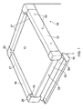
- Fig. 1 shows an assembly 10 for mounting a roofing material 12 on a flat roof of a fixture such as a building 14.
- a roofing material 12 may comprise a rubber based membrane which may be adhered to the building 14 or for instance retained thereon on by ballast lying thereon.
- a gutter 16 is provided on one side of the building 14.
- the assembly 10 provides an upstanding edge 17 along the other three sides of the building 14.
- the edge 17 is provided by three lengths of an extruded retaining member 18 which may be made for example of a plastics material such as PVC.
- the retaining member 18 has a generally L-shaped configuration with a shorter limb of the L being provided by a hollow rectangular box section 20, and the other limb by a planar strip 22.
- the box section 20 locates on top of the material 12, which material 12 then overlaps onto the side of the building 14 for a short distance, and is overlaid by the strip 22.
- the strip 22 is mounted to the building 14 as shown for example by three screws or nails, and hole covers 24 may be provided to cover the ends of the screws/nails.
- Outside corner members 26 are provided which have two planar outer strips 28 perpendicular to each other, spaced from two inner shorter planar strips 30 by a L shape cover part 32.
- the corner members 26 are of a size to slidingly locate over the ends of adjacent perpendicular retaining members 18.
- first and second components 36, 38 are formed as extrusions for example of PVC.
- the first component 36 is mountable to the side of the building 14 immediately below the top thereof.
- the component 36 has three hollow compartments 40, 42, 44 one below each other from the top.
- a downwardly curving outwardly extending lip 46 is provided at the top of the uppermost compartment 40.
- the next compartment 42 is slightly inwardly recessed and is smaller.
- a screw or nail is provided extending through the compartment 42 to mount the component 36 on the building 14.
- the recessing of the compartment 42 receives the head of the screw or nail.
- Beneath the lowermost compartment 44 a recess 48 is provided with lips 50 forming a resilient outward facing opening to the recess 48.
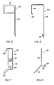
- the second component 38 has an upper planar part 52, and a lower slightly shorter planar part 54 inclined outwardly and downwardly relative to the part 52 in use as shown in Fig. 8 .
- the lower part 54 acts as a deflector for water to urge the water into the gutter 16.
- a male extension 56 is provided at the meeting of the upper and lower parts 52, 54, and extends perpendicular to the upper part 52.
- the male extension 56 has an arrowhead 58.
- the first component 36 is mounted to the building 14, and the material 12 extends thereover.
- the second component 38 is then brought into engagement urging the material 12 against the first component 36.
- the top of the upper part 54 is located beneath the lip 46, and the second component 38 is pushed towards the first component 36 such that the male extension 56 locates in the recess 48.
- the shape of the arrowhead 58 and the lips 50 provide for an automatic interengagement therebetween. This arrangement clamps the material 12 in place.
- Fig. 6 shows a clip 60 usable when joining together two lengths of retaining member 18 as shown in Fig. 2 .
- the clip 60 has a generally n shape, but with one limb 64 significantly longer than the other 66 to correspond to the sectional exterior shape of the retaining member 18.
- Sprung lips 68 are provided on the inside of the lower limbs 64, 66 on the n, to retain the clip 60 on the retaining members 18 once in position.
- Fig. 9 shows an inside corner member 70, for internal right angles between two walls, as illustrated in Fig. 2 .
- the inside corner member 70 has longer perpendicular inner planar sections 72 and shorter perpendicular outer planar sections 74 interconnected by an L shape cover part 76.
- the inside corner member 70 is of a size to slidingly locate over the ends of adjacent perpendicular retaining members 18.
- Fig. 11 shows an end cap 78 with a planar face 80 and three tapering resilient fingers 82 on an inner side of the face 80.
- the end cap 78 can close the end of the box section 20 in a friction fit, or a part of the corner members 26, 70 when adjacent an elongate retaining arrangement 34, as shown in Fig. 1 .
- Different shaped end caps may be provided if required.
- sealant may be provided at a number of locations such as between the first and second components 36, 38 adjacent the lip 46. Sealant would usually also be provided beneath the box sections 20 of the retaining members 18 and in particular to prevent debris becoming trapped beneath the box section 20 and material 12. Sealant could also be used between the corner members 26, 70 and the retaining members 18 or retaining arrangements 34. Sealant could be used to close for instance open ends of lengths of the retaining member 18, and could be provided around the joining clips 60.
- the assembly generally removes the need for any fixings to pass through the roofing material, thereby avoiding the potential problems outlined above.
- Different components of the assembly can be used as required for different shapes and sizes of roofs.
- the assembly can readily be installed to provide long term and reliable operation. Such assemblies can be fitted on newly built roofs, or can readily be retrofitted to existing roofs.
Landscapes
- Engineering & Computer Science (AREA)
- Architecture (AREA)
- Civil Engineering (AREA)
- Structural Engineering (AREA)
- Roof Covering Using Slabs Or Stiff Sheets (AREA)
Applications Claiming Priority (1)
| Application Number | Priority Date | Filing Date | Title |
|---|---|---|---|
| GB0721976A GB2454499B (en) | 2007-11-09 | 2007-11-09 | Mounting assembly |
Publications (2)
| Publication Number | Publication Date |
|---|---|
| EP2058449A2 true EP2058449A2 (de) | 2009-05-13 |
| EP2058449A3 EP2058449A3 (de) | 2014-04-30 |
Family
ID=38858396
Family Applications (1)
| Application Number | Title | Priority Date | Filing Date |
|---|---|---|---|
| EP08253407.4A Withdrawn EP2058449A3 (de) | 2007-11-09 | 2008-10-21 | Montageanordnung für eine Dachabdeckung |
Country Status (2)
| Country | Link |
|---|---|
| EP (1) | EP2058449A3 (de) |
| GB (1) | GB2454499B (de) |
Families Citing this family (2)
| Publication number | Priority date | Publication date | Assignee | Title |
|---|---|---|---|---|
| GB2498138B (en) * | 2012-06-21 | 2014-01-29 | Matthew James Wyndham East | A low slope roof edge membrane retaining & sealing system |
| CN112031244B (zh) * | 2020-09-03 | 2022-11-01 | 贵州汇通申发钢结构有限公司 | 嵌套式钢结构的装配式建筑屋顶架 |
Family Cites Families (16)
| Publication number | Priority date | Publication date | Assignee | Title |
|---|---|---|---|---|
| US873407A (en) * | 1907-08-24 | 1907-12-10 | William Behl | Eaves-strip. |
| US1299421A (en) * | 1915-11-05 | 1919-04-08 | William Boss | Metal roof-edging. |
| FR1448963A (fr) * | 1965-06-29 | 1966-03-18 | Recouvrement de bordure pour toitures plates, toits en pente, planchers de terrasses, et analogues | |
| GB1392179A (en) * | 1971-06-24 | 1975-04-30 | Cook R S | Roof fitments |
| US4037372A (en) * | 1975-06-09 | 1977-07-26 | Johns-Manville Corporation | Roof facia arrangement |
| US4067152A (en) * | 1976-12-17 | 1978-01-10 | Philip L. Johnson | Fascia compression clip |
| US4231141A (en) * | 1978-07-26 | 1980-11-04 | Derrick Danny O | Attachment device for flexible films and fabrics |
| US4598507A (en) * | 1981-10-06 | 1986-07-08 | W. P. Hickman Company | Roof edge construction |
| US4586301A (en) * | 1984-08-06 | 1986-05-06 | W. P. Hickman Company | Retainer clamp membrane fastening system |
| US4665667A (en) * | 1985-11-08 | 1987-05-19 | Taylor William T | Fascia including means for rigidly securing a membrane in place |
| US4707954A (en) * | 1986-03-03 | 1987-11-24 | Butzen William J | Roof edge fascia system |
| US4980997A (en) * | 1989-11-09 | 1991-01-01 | A-1 All Weather Roofing, Inc. | Roofing system with integral gutter |
| DE29521345U1 (de) * | 1995-12-11 | 1997-01-02 | Stoll, Achim, 75389 Neuweiler | Randabdeckungsprofil |
| US5927023A (en) * | 1996-11-26 | 1999-07-27 | Metal-Era, Inc. | Roof edge fascia system for securing a membrane in place |
| US6845590B1 (en) * | 2002-05-10 | 2005-01-25 | Southern Aluminum Finishing Company, Inc. | Fascia systems for roof edges |
| GB0616540D0 (en) * | 2006-08-19 | 2006-09-27 | Cole David R | UPVC roof trims |
-
2007
- 2007-11-09 GB GB0721976A patent/GB2454499B/en active Active
-
2008
- 2008-10-21 EP EP08253407.4A patent/EP2058449A3/de not_active Withdrawn
Also Published As
| Publication number | Publication date |
|---|---|
| GB2454499A (en) | 2009-05-13 |
| GB0721976D0 (en) | 2007-12-19 |
| EP2058449A3 (de) | 2014-04-30 |
| GB2454499B (en) | 2010-05-05 |
Similar Documents
| Publication | Publication Date | Title |
|---|---|---|
| US11560748B2 (en) | Prefabricated flashing product | |
| RU2103468C1 (ru) | Гидроизоляционное устройство для окон, в частности для окон в крыше | |
| US7331145B2 (en) | Flashing component for a roof window assembly | |
| US20090031640A1 (en) | Roof Flashing Connections | |
| US5263287A (en) | Roofing membrane flashing | |
| RU2139981C1 (ru) | Гидроизолирующее устройство | |
| US7591109B2 (en) | Rib vent system for roofing panels | |
| US9187905B2 (en) | Roof or window panel to metal roofing or siding interface securement system | |
| US7392625B2 (en) | Nail fin for window frame assembly | |
| EP3822424B1 (de) | Dachrand | |
| EP2447438A2 (de) | Abdecken mit einem Befestigungselement, Versiegeln der Verbindung der Dachhaut mit einer das Dach durchdringenden Struktur und einer Schnappverbindung zwischen den Abdeckungen | |
| EP2058449A2 (de) | Montageanordnung für eine Dachabdeckung | |
| US9745790B2 (en) | Prefabricated flashing product | |
| US9745789B2 (en) | Prefabricated flashing product | |
| EP4499942B1 (de) | Unterdachkragen, kit mit einem unterdachkragen und dachfenster, montiertes dachfenster und verfahren zur abdichtung der verbindung zwischen einem dachfenster und einer dachstruktur | |
| US6418679B2 (en) | Skylight curb seal and method | |
| GB2461823A (en) | An assembly for mounting a roofing material on a building | |
| US20090025319A1 (en) | Installation system for window and door assemblies | |
| AU700723B2 (en) | A roof gutter | |
| CA2716277A1 (en) | Method and apparatus for sealing pool fixtures to vinyl pool liners |
Legal Events
| Date | Code | Title | Description |
|---|---|---|---|
| PUAI | Public reference made under article 153(3) epc to a published international application that has entered the european phase |
Free format text: ORIGINAL CODE: 0009012 |
|
| AK | Designated contracting states |
Kind code of ref document: A2 Designated state(s): AT BE BG CH CY CZ DE DK EE ES FI FR GB GR HR HU IE IS IT LI LT LU LV MC MT NL NO PL PT RO SE SI SK TR |
|
| AX | Request for extension of the european patent |
Extension state: AL BA MK RS |
|
| RIC1 | Information provided on ipc code assigned before grant |
Ipc: E04D 1/30 20060101ALI20131127BHEP Ipc: E04B 7/02 20060101AFI20131127BHEP |
|
| PUAL | Search report despatched |
Free format text: ORIGINAL CODE: 0009013 |
|
| AK | Designated contracting states |
Kind code of ref document: A3 Designated state(s): AT BE BG CH CY CZ DE DK EE ES FI FR GB GR HR HU IE IS IT LI LT LU LV MC MT NL NO PL PT RO SE SI SK TR |
|
| AX | Request for extension of the european patent |
Extension state: AL BA MK RS |
|
| RIC1 | Information provided on ipc code assigned before grant |
Ipc: E04D 1/30 20060101ALI20140326BHEP Ipc: E04B 7/02 20060101AFI20140326BHEP |
|
| 17P | Request for examination filed |
Effective date: 20140616 |
|
| RBV | Designated contracting states (corrected) |
Designated state(s): AT BE BG CH CY CZ DE DK EE ES FI FR GB GR HR HU IE IS IT LI LT LU LV MC MT NL NO PL PT RO SE SI SK TR |
|
| STAA | Information on the status of an ep patent application or granted ep patent |
Free format text: STATUS: THE APPLICATION HAS BEEN WITHDRAWN |
|
| 18W | Application withdrawn |
Effective date: 20141009 |