EP2058516A2 - Mikrofluidische osmotische Pumpe - Google Patents
Mikrofluidische osmotische Pumpe Download PDFInfo
- Publication number
- EP2058516A2 EP2058516A2 EP08168781A EP08168781A EP2058516A2 EP 2058516 A2 EP2058516 A2 EP 2058516A2 EP 08168781 A EP08168781 A EP 08168781A EP 08168781 A EP08168781 A EP 08168781A EP 2058516 A2 EP2058516 A2 EP 2058516A2
- Authority
- EP
- European Patent Office
- Prior art keywords
- fluid
- osmotic
- microfluidic
- surrounding compartment
- fluid reservoir
- Prior art date
- Legal status (The legal status is an assumption and is not a legal conclusion. Google has not performed a legal analysis and makes no representation as to the accuracy of the status listed.)
- Withdrawn
Links
Images

Classifications
-
- F—MECHANICAL ENGINEERING; LIGHTING; HEATING; WEAPONS; BLASTING
- F04—POSITIVE - DISPLACEMENT MACHINES FOR LIQUIDS; PUMPS FOR LIQUIDS OR ELASTIC FLUIDS
- F04B—POSITIVE-DISPLACEMENT MACHINES FOR LIQUIDS; PUMPS
- F04B19/00—Machines or pumps having pertinent characteristics not provided for in, or of interest apart from, groups F04B1/00 - F04B17/00
- F04B19/006—Micropumps
-
- A—HUMAN NECESSITIES
- A61—MEDICAL OR VETERINARY SCIENCE; HYGIENE
- A61M—DEVICES FOR INTRODUCING MEDIA INTO, OR ONTO, THE BODY; DEVICES FOR TRANSDUCING BODY MEDIA OR FOR TAKING MEDIA FROM THE BODY; DEVICES FOR PRODUCING OR ENDING SLEEP OR STUPOR
- A61M5/00—Devices for bringing media into the body in a subcutaneous, intra-vascular or intramuscular way; Accessories therefor, e.g. filling or cleaning devices, arm rests
- A61M5/14—Infusion devices, e.g. infusing by gravity; Blood infusion; Accessories therefor
- A61M5/142—Pressure infusion, e.g. using pumps
- A61M5/145—Pressure infusion, e.g. using pumps using pressurised reservoirs, e.g. by means of pistons
- A61M5/148—Pressure infusion, e.g. using pumps using pressurised reservoirs, e.g. by means of pistons flexible
- A61M5/1483—Pressure infusion, e.g. using pumps using pressurised reservoirs, e.g. by means of pistons flexible using flexible bags externally pressurised by fluid pressure
- A61M5/1486—Pressure infusion, e.g. using pumps using pressurised reservoirs, e.g. by means of pistons flexible using flexible bags externally pressurised by fluid pressure the bags being substantially completely surrounded by fluid
-
- F—MECHANICAL ENGINEERING; LIGHTING; HEATING; WEAPONS; BLASTING
- F04—POSITIVE - DISPLACEMENT MACHINES FOR LIQUIDS; PUMPS FOR LIQUIDS OR ELASTIC FLUIDS
- F04B—POSITIVE-DISPLACEMENT MACHINES FOR LIQUIDS; PUMPS
- F04B17/00—Pumps characterised by combination with, or adaptation to, specific driving engines or motors
-
- Y—GENERAL TAGGING OF NEW TECHNOLOGICAL DEVELOPMENTS; GENERAL TAGGING OF CROSS-SECTIONAL TECHNOLOGIES SPANNING OVER SEVERAL SECTIONS OF THE IPC; TECHNICAL SUBJECTS COVERED BY FORMER USPC CROSS-REFERENCE ART COLLECTIONS [XRACs] AND DIGESTS
- Y10—TECHNICAL SUBJECTS COVERED BY FORMER USPC
- Y10T—TECHNICAL SUBJECTS COVERED BY FORMER US CLASSIFICATION
- Y10T436/00—Chemistry: analytical and immunological testing
- Y10T436/11—Automated chemical analysis
-
- Y—GENERAL TAGGING OF NEW TECHNOLOGICAL DEVELOPMENTS; GENERAL TAGGING OF CROSS-SECTIONAL TECHNOLOGIES SPANNING OVER SEVERAL SECTIONS OF THE IPC; TECHNICAL SUBJECTS COVERED BY FORMER USPC CROSS-REFERENCE ART COLLECTIONS [XRACs] AND DIGESTS
- Y10—TECHNICAL SUBJECTS COVERED BY FORMER USPC
- Y10T—TECHNICAL SUBJECTS COVERED BY FORMER US CLASSIFICATION
- Y10T436/00—Chemistry: analytical and immunological testing
- Y10T436/25—Chemistry: analytical and immunological testing including sample preparation
- Y10T436/2575—Volumetric liquid transfer
Definitions
- the present invention relates to a microfluidic osmotic pump. More particularly, the present invention relates to a microfluidic osmotic pump that is capable of on-chip pumping without any external power input.
- micro-sized devices be used in a variety of applications from medicine to biochemistry.
- An advantage of the use of these microfluidic devices is that at micro levels, it is much easier to ensure experimental precision because of the laminar flow of fluids at such scales.
- microfluidic devices find application in molecular biology procedures for enzymatic analysis, DNA analysis, proteomics and clinical pathology. All of these high-end applications are based on a continuous flow of a predetermined liquid through microfabricated channels.
- the actuation of the liquid flow is normally achieved by the application of external pressure, external mechanical micro-pumping or by electrokinetic pumping effected through the application of a voltage potential.
- an osmotic pump that is capable of microfluidic on-chip pumping without the application of an external pressure or electrokinetic or external mechanical pumping.
- microfluidic devices are suitable for use in a drop-on-demand inkjet printing devices for ejecting printing ink in a suitable manner.
- These devices usually take the form of an inkjet printhead that is capable of being incorporated within conventional printing devices such as printers, copiers and facsimile machines.
- printing devices such as printers, copiers and facsimile machines.
- use of such devices for inkjet printing is exemplary and such devices may find use in other applications wherein small and a controlled amount of fluid ejection on demand is desired.
- the microfluidic devices may be used for delivering pharmaceutically beneficial agents in a controlled and regulated manner over a preselected time or administration period.
- These devices usually comprise a piston with a recess for imbibing an osmotic agent, which actuates the piston to release corresponding amounts of the beneficial agent.
- a piston makes the micro-level fabrication of these devices cumbersome and therefore cost-intensive.
- the use of a piston reduces the space efficiency of the microfluidic device because the space occupied by the piston compromises either the amount of the osmotic agent, which leads to an insufficient pumping or the amount of the beneficial agent, which is again undesirable.
- These devices conventionally comprise a contractible chamber and duct interconnecting a fluid reservoir with a destination.
- these microfluidic devices may be used for cooling of electronic devices, wherein the reservoir may contain the cooling agent and the destination is an electronic device that requires cooling.
- the fluid reservoir may act as a fuel tank supplying predetermined amount of fuel to a miniature engine.
- the reservoir may contain a specimen which may be assayed on an observation slide.
- the reservoir may contain a chemical reagent which is fed to a process stream destination enabling a controlled stoichiometric chemical reaction.
- the reservoir may contain a colorant which may be fed to a colorant application system.
- PCT Publication No. 2004/054811 discloses a microfluidic actuator for ejecting ink through a nozzle comprising a deflectable membrane, an actuator chamber and a nanostructure.
- the nanostructure deflects towards the membrane upon application of an operating voltage which deflects the membrane causing the ink ejection through the nozzle.
- the present invention solves the need for a microfluidic osmotic pump which enables on-chip pumping of a fluid without the application of an external voltage field.
- US Patent Publication 2005/0070884 A1 discloses an osmotic pump comprising a vent that allows a gradual venting of osmotic material after the drug formulation in the osmotic pump is delivered. It had been observed that subsequent to the delivery of the beneficial agent, the remaining osmotic agent continued to imbibe water from the environment of operation leading to a gradual increase in pressure within the system. With the passage of time, it was seen that due to an incessant gradual increase in pressure, any component of the osmotic pump gets compromised or physically separated. Moreover, the disclosed osmotic pump necessarily includes a piston, which as seen above, reduces the space efficiency of the microfluidic device apart from increasing the fabrication complexity and the associated manufacturing costs thereof.
- US Patent Publication 2006/0111693 discloses an osmotic pump having a space efficient piston housed within a capsule.
- the described piston acts as a movable seal which separates the osmotic agent from the beneficial agent.
- the finding of the disclosed invention is that a piston having a length to total diameter ratio of about 1.1:1 and a core diameter to total diameter ratio of about 0.9:1 enables greater beneficial agent and/or osmotic agent payload without substantially increasing the size of the payload.
- microfluidic osmotic pump that is capable of on-chip pumping a desired fluid to a predetermined destination without any external power input.
- Another object of the present invention is to provide a microfluidic osmotic pump that is capable of pumping a desired fluid to a predetermined destination in a controlled and regulated manner over a preselected time or administration period.
- Yet another object of the present invention is to provide a microfluidic osmotic pump that eliminates the use of a piston thereby enhancing the space efficiency of the osmotic pump without comprising the amount of an osmotic agent or the desired fluid delivered to a predetermined destination.
- Another object of the present invention is to provide a microfluidic osmotic pump which utilizes an osmotic agent to drive a desired fluid to a predetermined destination thereby avoiding the use of an external power input.
- Another object of the present invention is to provide a microfluidic osmotic pump wherein the pumping rate of the desired fluid is a function of the permeability of a semi-permeable membrane or the characteristics of the osmotic agent and is therefore easily controllable.
- Yet another object of the present invention is to provide a microfluidic osmotic pump that is capable of delivering a very low and accurate flow rate of a desired fluid at a predetermined destination.
- the present invention provides a microfluidic osmotic pump capable of delivering a desired fluid at a predetermined destination comprising an inside fluid reservoir housing a compressible sac, a surrounding compartment having an external surface made up of a semi-permeable membrane and a fluid duct.
- the inside fluid reservoir houses a compressible sac containing a predetermined amount of a fluid that is desired to be pumped to a predetermined destination.
- the surrounding compartment holds a desired osmotic agent and its saturated solution in the remaining volume thereof.
- the surrounding compartment has an outer surface made up of a semi-permeable membrane that allows a predetermined second external fluid to permeate into the surrounding compartment but is substantially impermeable to the osmotic agent held within the surrounding compartment.
- the fluid duct is substantially housed within the inside fluid reservoir and runs through openings provided through the inside fluid reservoir and the surrounding compartment.
- the fluid duct has a first end immersed in the desired fluid held within the inside fluid reservoir and a second end protruding out of the microfluidic osmotic pump.
- the semi-permeable membrane outer surface of the surrounding compartment allows the external fluid to permeate into the surrounding compartment and solvate the osmotic agent contained within the surrounding compartment to a resulting solvated osmotic agent.
- the solvated osmotic agent thus produced is dissolved into the saturated solution held within the surrounding compartment thereby developing an osmotic pressure.
- the osmotic pressure thus developed compresses the compressible sac housed within the inside fluid reservoir to pump out the fluid held within the sac through the fluid duct.
- Figure 1 illustrates a microfluidic osmotic pump in accordance with the present invention.
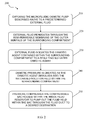
- Figure 2 illustrates a method utilizing a microfluidic osmotic pump in accordance with the present invention.
- a microfluidic osmotic pump capable of delivering a desired fluid at a predetermined destination comprising: an inside fluid reservoir adapted to contain a predetermined amount of a first desired fluid within a compressible sac housed within said inside fluid reservoir; a surrounding compartment that houses said fluid reservoir and is adapted to hold a desired osmotic agent and its saturated solution in a desired second external fluid in the remaining volume thereof; said surrounding compartment having an outer surface made up of a semi-permeable membrane that allows said predetermined second external fluid to permeate through the semi-permeable membrane into said surrounding compartment but is substantially impermeable to said osmotic agent held within said surrounding compartment; and a fluid duct substantially housed within said inside fluid reservoir that runs through openings provided through said inside fluid reservoir and said surrounding compartment, said fluid duct having a first end immersed in the desired fluid held within said inside fluid reservoir and a second end protruding out of the microfluidic osmotic pump.
- a microfluidic osmotic pump 100 capable of delivering a desired fluid at a predetermined destination comprising an inside fluid reservoir 102 housing a compressible sac 103, a surrounding compartment 101 having an external surface 104 made up of a semi-permeable membrane and a fluid duct 105.
- the inside fluid reservoir 102 houses a compressible sac 103 containing a predetermined amount of a fluid (not shown) that is desired to be pumped to a predetermined destination (not shown).
- the surrounding compartment 101 holds a desired osmotic agent 106 and its saturated solution in the volume remaining between the surrounding compartment and the compressible sac 103.
- the surrounding compartment 101 has an outer surface made up of a semi-permeable membrane that allows a predetermined external fluid (not shown) to permeate into the surrounding compartment but is substantially impermeable to the osmotic agent 106 held within the surrounding compartment.
- the fluid duct 105 is substantially housed within the inside the compressible sac 103 held within the fluid reservoir 102 and enables a desired fluid (not shown) held within the compressible sac 103 to run through openings 107 and out through 108 to a predetermined destination. The desired fluid flows from the compressible sac 103 when pressure is formed within the fluid reservoir 102 formed inside the surrounding compartment 101.
- the fluid duct 105 is attached as shown at location 109 with the compressible sac 103 and has a first end 107 immersed in the desired fluid held within the compressible sac 102 and a second end 108 protruding out of the surrounding compartment 101 defining an outer housing of microfluidic osmotic pump.
- the fluid duct 105 is sealed at its location of attachment 110 and exit point through the surrounding compartment 101.
- the microscopic osmotic pump During the operation of the microscopic osmotic pump, it is exposed to a predetermined external fluid.
- the semi-permeable membrane of the outer surface of the surrounding compartment allows the external fluid to permeate into the surrounding compartment and solvate the osmotic agent contained within the surrounding compartment to a resulting solvated osmotic agent.
- the solvated osmotic agent thus produced is dissolved into the saturated solution held within the surrounding compartment thereby developing an osmotic pressure.
- the osmotic pressure thus developed compresses the compressible sac housed within the inside fluid reservoir to pump out the fluid held within the sac through the fluid duct.
- the present invention further provides a method for delivering a desired fluid at a predetermined destination.
- the method begins by exposing the microfluidic osmotic pump described above to a predetermined external fluid as shown in Block 210.
- the external fluid permeates through the semi-permeable membrane of the outer surface of the surrounding compartment as shown in Block 120, and the external fluid solvates the osmotic agent contained within the surrounding compartment to a resulting solvated osmotic agent as shown in Block 130.
- An osmotic pressure is created as the osmotic agent dissolves into the saturated solution held within the surrounding compartment as shown in Block 140.
- the pressure compresses the compressible sac housed within the inside fluid reservoir to pump out the fluid held within the sac through the fluid duct to a desired destination as shown in Block 150.
- the outer surface of the surrounding compartment composed of a semi-permeable membrane allows only water to permeate inside the surrounding compartment, where it comes into contact with the osmotic agent to form hydrated osmotic agent.
- the hydrated osmotic agent goes into the saturated solution of the osmotic agent in water, which was previously housed within the surrounding compartment.
- the saturated solution does not imbibe the osmotic agent before its hydration though being housed within the same surrounding compartment due to its saturation, which prevents it from dissolving further solute without being hydrated.
- the dissolution of the hydrated osmotic agent develops an osmotic pressure which compresses the compressible sac inside the fluid reservoir thereby providing the necessary force to pump the fluid contained within the sac to any predetermined destination.
- the pumping rate of the desired fluid is a function of the osmotic agent and water permeability of the semi-permeable membrane. It has been seen that a greater water permeability of the semi-permeable membrane results in a higher pumping rate of a desired fluid.
- the microfluidic osmotic pump of the present invention is capable of delivering a very low and accurate flow rate that is desirable in many applications. For example, it has been made possible to attain flow rates of the desired fluid from 2 to 150 nL/min by varying the parameters such as the choice of the osmotic agent, water permeability of the chosen semi-permeable membrane and the choice of the solvating fluid. It was further found that at a flow rate of 150 nL/min, a 0.9 mL of a desired fluid was pumped in a controlled manner over a time period of 100 hours of continuous operation.
- the osmotic agent is selected from a group consisting of NaC1, KCl, MgSO4 and mixture of them.
- the semi-permeable membrane is selected from a group consisting of cellulose acetate, PTFE, and polyvinylacetate (PVAC).
- Typical permeability values of the semi-permeable membranes found suitable for use in the osmotic pumps of the present invention varied from 4.5 ⁇ 10 -12 ⁇ l mm / (s mm 2 Pa) to 4.5 ⁇ 10 -7 ⁇ l mm / (s mm 2 Pa).
- the osmotic pump of the present invention is capable of being embedded into a microfluidic chip of credit card like dimensions to facilitate active on chip pumping, which finds use in a variety of non-limiting applications such as those described hereinabove under the background.
- the microfluidic osmotic pump of the present invention may find application as the inkjet head for drop-on-demand inkjet printing or may be used in systems requiring precise control of fluid delivery through a chip such as those in biosciences or nano-chemistry.
- the microfluidic osmotic pumps of the present invention may be embedded on a microfluidic transmitter through a batch process, which allows seamless interfacing of microfluidic pumping with light emitting chemistry.
- the inside fluid reservoir is loaded with a pusher fluid, which is immiscible with another chemiluminescence fluid.
- the osmotic pumps of the present invention may thereafter be integrated with a microfluidic circuit wherein the pusher fluid that provides the shearing source and the continuous phase that carries an intermittent slug to be delivered through a barcode window.
- the microfluidic osmotic pumps of the present invention may be embedded on a microfluidic transmitter using methods that are conventionally known in the art including lamination and injection molding.
- the embedded card may be designed and fabricated for use as an off-the-shelf osmotic pump, whose performance may be accurately predicted and experimentally verified.
- the osmotic pump may be fabricated on a flat card size substrate using methods such as dry powder deposition, membrane lamination, blister packaging and multilayer lamination technology.
- the card sized substrate may thereafter be readily inserted into a plastic cartridge for printing use.
- microfluidic osmotic pumps may find application in molecular biology procedures for enzymatic analysis, DNA analysis, proteomics and clinical pathology.
- the microfluidic osmotic pumps according to the present invention may be used for delivering pharmaceutically beneficial agents in a controlled and regulated manner over a preselected time or administration period.
- the beneficial agent may be housed within the described inside fluid reservoir.
- the osmotic pump may be actuated to release controlled amounts of the beneficial agent over a predetermined administration period for a controlled and regulated delivery of the beneficial agent.
- the microfluidic osmotic pumps according to the present invention may be used for cooling electronic devices, wherein the inside fluid reservoir may contain the cooling agent and the desired destination for delivering the cooling agent may be an electronic device that requires cooling.
- the inside fluid reservoir may act as a fuel tank supplying predetermined amount of fuel to a miniature engine.
- the reservoir may contain a specimen which may be assayed on an observation slide.
- the inside fluid reservoir may contain a chemical reagent, which is fed to a process stream destination enabling a controlled stoichiometric chemical reaction.
- the reservoir may contain a colorant which may be fed to a colorant application system.
Landscapes
- Engineering & Computer Science (AREA)
- Health & Medical Sciences (AREA)
- Mechanical Engineering (AREA)
- General Engineering & Computer Science (AREA)
- Biomedical Technology (AREA)
- Fluid Mechanics (AREA)
- Vascular Medicine (AREA)
- Anesthesiology (AREA)
- Physics & Mathematics (AREA)
- Heart & Thoracic Surgery (AREA)
- Hematology (AREA)
- Life Sciences & Earth Sciences (AREA)
- Animal Behavior & Ethology (AREA)
- General Health & Medical Sciences (AREA)
- Public Health (AREA)
- Veterinary Medicine (AREA)
- Reciprocating Pumps (AREA)
Applications Claiming Priority (1)
| Application Number | Priority Date | Filing Date | Title |
|---|---|---|---|
| US11/983,255 US8394644B2 (en) | 2007-11-08 | 2007-11-08 | Microfluidic osmotic pump |
Publications (2)
| Publication Number | Publication Date |
|---|---|
| EP2058516A2 true EP2058516A2 (de) | 2009-05-13 |
| EP2058516A3 EP2058516A3 (de) | 2010-01-20 |
Family
ID=40344574
Family Applications (1)
| Application Number | Title | Priority Date | Filing Date |
|---|---|---|---|
| EP08168781A Withdrawn EP2058516A3 (de) | 2007-11-08 | 2008-11-10 | Mikrofluidische osmotische Pumpe |
Country Status (2)
| Country | Link |
|---|---|
| US (1) | US8394644B2 (de) |
| EP (1) | EP2058516A3 (de) |
Families Citing this family (2)
| Publication number | Priority date | Publication date | Assignee | Title |
|---|---|---|---|---|
| JP5311801B2 (ja) * | 2007-11-09 | 2013-10-09 | キヤノン株式会社 | 浸透圧ポンプを用いた送液駆動機構および該送液駆動機構を有するマイクロチップ |
| WO2019023617A1 (en) * | 2017-07-27 | 2019-01-31 | University Of Utah Research Foundation | DEVICE FOR DELIVERY OF THERAPEUTIC PRODUCT |
Citations (4)
| Publication number | Priority date | Publication date | Assignee | Title |
|---|---|---|---|---|
| US3760805A (en) | 1971-01-13 | 1973-09-25 | Alza Corp | Osmotic dispenser with collapsible supply container |
| WO2004054811A2 (en) | 2002-12-12 | 2004-07-01 | Brother Industries, Ltd. | Nanostructure based microfluidic pumping device and method |
| US20050070884A1 (en) | 2003-03-31 | 2005-03-31 | Dionne Keith E. | Osmotic pump with means for dissipating internal pressure |
| US20060111693A1 (en) | 2002-06-26 | 2006-05-25 | Lautenbach Scott D | Minimally compliant, volume-efficient piston for osmotic drug delivery systems |
Family Cites Families (16)
| Publication number | Priority date | Publication date | Assignee | Title |
|---|---|---|---|---|
| US4034756A (en) | 1971-01-13 | 1977-07-12 | Alza Corporation | Osmotically driven fluid dispenser |
| US3865108A (en) * | 1971-05-17 | 1975-02-11 | Ortho Pharma Corp | Expandable drug delivery device |
| US4111202A (en) * | 1976-11-22 | 1978-09-05 | Alza Corporation | Osmotic system for the controlled and delivery of agent over time |
| US4203442A (en) * | 1977-08-29 | 1980-05-20 | Alza Corporation | Device for delivering drug to a fluid environment |
| US4180073A (en) * | 1977-08-29 | 1979-12-25 | Alza Corporation | Device for delivering drug to biological environment |
| US4320758A (en) * | 1979-05-07 | 1982-03-23 | Alza Corporation | Osmotically driven fluid dispenser |
| US4340054A (en) * | 1980-12-29 | 1982-07-20 | Alza Corporation | Dispenser for delivering fluids and solids |
| US4595583A (en) * | 1984-03-19 | 1986-06-17 | Alza Corporation | Delivery system controlled administration of beneficial agent to ruminants |
| US5169390A (en) | 1990-05-21 | 1992-12-08 | Athayde Amulya L | Osmotic infusion device |
| US5290240A (en) | 1993-02-03 | 1994-03-01 | Pharmetrix Corporation | Electrochemical controlled dispensing assembly and method for selective and controlled delivery of a dispensing fluid |
| US20020100714A1 (en) * | 2001-01-31 | 2002-08-01 | Sau Lan Tang Staats | Microfluidic devices |
| US20030232203A1 (en) | 2002-01-18 | 2003-12-18 | The Regents Of The University Of Michigan | Porous polymers: compositions and uses thereof |
| WO2005007223A2 (en) * | 2003-07-16 | 2005-01-27 | Sasha John | Programmable medical drug delivery systems and methods for delivery of multiple fluids and concentrations |
| US7355277B2 (en) | 2003-12-31 | 2008-04-08 | Intel Corporation | Apparatus and method integrating an electro-osmotic pump and microchannel assembly into a die package |
| US7458783B1 (en) | 2004-06-30 | 2008-12-02 | Intel Corporation | Method and apparatus for improved pumping medium for electro-osmotic pumps |
| US20070109695A1 (en) * | 2005-11-15 | 2007-05-17 | Functional Devices, Inc. | Multiple UL class II secondary power sources |
-
2007
- 2007-11-08 US US11/983,255 patent/US8394644B2/en not_active Expired - Fee Related
-
2008
- 2008-11-10 EP EP08168781A patent/EP2058516A3/de not_active Withdrawn
Patent Citations (4)
| Publication number | Priority date | Publication date | Assignee | Title |
|---|---|---|---|---|
| US3760805A (en) | 1971-01-13 | 1973-09-25 | Alza Corp | Osmotic dispenser with collapsible supply container |
| US20060111693A1 (en) | 2002-06-26 | 2006-05-25 | Lautenbach Scott D | Minimally compliant, volume-efficient piston for osmotic drug delivery systems |
| WO2004054811A2 (en) | 2002-12-12 | 2004-07-01 | Brother Industries, Ltd. | Nanostructure based microfluidic pumping device and method |
| US20050070884A1 (en) | 2003-03-31 | 2005-03-31 | Dionne Keith E. | Osmotic pump with means for dissipating internal pressure |
Also Published As
| Publication number | Publication date |
|---|---|
| EP2058516A3 (de) | 2010-01-20 |
| US20090123297A1 (en) | 2009-05-14 |
| US8394644B2 (en) | 2013-03-12 |
Similar Documents
| Publication | Publication Date | Title |
|---|---|---|
| EP1957794B1 (de) | Elektrokinetische pumpenausführungen und arzneimittelabgabesysteme | |
| TW201016477A (en) | Liquid supply system, method of manufacturing the liquid supply system, and method of manufacturing a liquid container | |
| US8187441B2 (en) | Electrochemical pump | |
| EP1865199A1 (de) | Flüssigkeitstransportvorrichtung und -system | |
| US8603834B2 (en) | Actuation of valves using electroosmotic pump | |
| CA2404735C (en) | A device for dispensing accurately-controlled small doses of liquid | |
| US20100288382A1 (en) | Fluid cartridge, pump and fluid valve arrangement | |
| WO2010055466A1 (en) | Interfacing an inlet to a capillary channel of a microfluidic system | |
| CN109569955B (zh) | 位移放大机构以及使用了该位移放大机构的液体喷射装置 | |
| US8394644B2 (en) | Microfluidic osmotic pump | |
| WO2007125456A2 (en) | Micropump with at least one gas releasing material | |
| US11590498B2 (en) | Arrangement for mixing fluids in a capillary driven fluidic system | |
| CN114096853B (zh) | 微流路器件、使用微流路器件的试验方法以及使用微流路器件的试验装置 | |
| CN100404121C (zh) | 微型反应器 | |
| EP3381699B1 (de) | Flüssigkeitsausstossvorrichtung und flüssigkeitsausstossverfahren | |
| Bodén et al. | On-chip liquid storage and dispensing for lab-on-a-chip applications | |
| EP1835213A1 (de) | Ventil und kapillare elektrobenetzungswirkung verwendendes stellglied | |
| US20190070603A1 (en) | System for charging and discharging air under a controlled pressure | |
| JP4129692B2 (ja) | バイオチップ製造方法及びバイオチップ製造装置 | |
| JP2009115755A (ja) | 浸透圧ポンプを用いた送液駆動機構および該送液駆動機構を有するマイクロチップ | |
| CN113244969A (zh) | 液体分配系统、微流体样品托架密封系统和使用该分配系统分配密封液的方法 | |
| US20150094196A1 (en) | Chamber component for a reagent vessel, and use thereof | |
| JPWO2009022496A1 (ja) | マイクロ検査チップおよび検査装置 | |
| JP2009019890A (ja) | マイクロ検査チップおよび検査装置 | |
| JP7167434B2 (ja) | 流体デバイス、リザーバー供給システムおよび流路供給システム |
Legal Events
| Date | Code | Title | Description |
|---|---|---|---|
| PUAI | Public reference made under article 153(3) epc to a published international application that has entered the european phase |
Free format text: ORIGINAL CODE: 0009012 |
|
| 17P | Request for examination filed |
Effective date: 20081110 |
|
| AK | Designated contracting states |
Kind code of ref document: A2 Designated state(s): AT BE BG CH CY CZ DE DK EE ES FI FR GB GR HR HU IE IS IT LI LT LU LV MC MT NL NO PL PT RO SE SI SK TR |
|
| AX | Request for extension of the european patent |
Extension state: AL BA MK RS |
|
| PUAL | Search report despatched |
Free format text: ORIGINAL CODE: 0009013 |
|
| AK | Designated contracting states |
Kind code of ref document: A3 Designated state(s): AT BE BG CH CY CZ DE DK EE ES FI FR GB GR HR HU IE IS IT LI LT LU LV MC MT NL NO PL PT RO SE SI SK TR |
|
| AX | Request for extension of the european patent |
Extension state: AL BA MK RS |
|
| RIC1 | Information provided on ipc code assigned before grant |
Ipc: A61M 5/148 20060101ALI20091216BHEP Ipc: A61K 9/00 20060101ALI20091216BHEP Ipc: F04B 17/00 20060101ALI20091216BHEP Ipc: F04B 19/00 20060101AFI20090219BHEP |
|
| 17Q | First examination report despatched |
Effective date: 20100129 |
|
| AKX | Designation fees paid |
Designated state(s): FR |
|
| REG | Reference to a national code |
Ref country code: DE Ref legal event code: 8566 |
|
| STAA | Information on the status of an ep patent application or granted ep patent |
Free format text: STATUS: THE APPLICATION HAS BEEN WITHDRAWN |
|
| 18W | Application withdrawn |
Effective date: 20110509 |