EP2058569A2 - Schließeinheit für eine Flüssigkeit, wie z.B. Gas, mit doppeltem Auslöser - Google Patents
Schließeinheit für eine Flüssigkeit, wie z.B. Gas, mit doppeltem Auslöser Download PDFInfo
- Publication number
- EP2058569A2 EP2058569A2 EP07425839A EP07425839A EP2058569A2 EP 2058569 A2 EP2058569 A2 EP 2058569A2 EP 07425839 A EP07425839 A EP 07425839A EP 07425839 A EP07425839 A EP 07425839A EP 2058569 A2 EP2058569 A2 EP 2058569A2
- Authority
- EP
- European Patent Office
- Prior art keywords
- trigger
- shaft
- engaged
- lever
- unit according
- Prior art date
- Legal status (The legal status is an assumption and is not a legal conclusion. Google has not performed a legal analysis and makes no representation as to the accuracy of the status listed.)
- Granted
Links
- 239000012530 fluid Substances 0.000 title claims description 14
- 230000014759 maintenance of location Effects 0.000 claims description 15
- 239000012190 activator Substances 0.000 claims description 6
- 239000012528 membrane Substances 0.000 claims description 3
- 230000010355 oscillation Effects 0.000 description 3
- 206010044565 Tremor Diseases 0.000 description 1
- 230000006835 compression Effects 0.000 description 1
- 238000007906 compression Methods 0.000 description 1
- 230000001419 dependent effect Effects 0.000 description 1
- ZZUFCTLCJUWOSV-UHFFFAOYSA-N furosemide Chemical compound C1=C(Cl)C(S(=O)(=O)N)=CC(C(O)=O)=C1NCC1=CC=CO1 ZZUFCTLCJUWOSV-UHFFFAOYSA-N 0.000 description 1
- 238000012986 modification Methods 0.000 description 1
- 230000004048 modification Effects 0.000 description 1
Images


Classifications
-
- F—MECHANICAL ENGINEERING; LIGHTING; HEATING; WEAPONS; BLASTING
- F16—ENGINEERING ELEMENTS AND UNITS; GENERAL MEASURES FOR PRODUCING AND MAINTAINING EFFECTIVE FUNCTIONING OF MACHINES OR INSTALLATIONS; THERMAL INSULATION IN GENERAL
- F16K—VALVES; TAPS; COCKS; ACTUATING-FLOATS; DEVICES FOR VENTING OR AERATING
- F16K17/00—Safety valves; Equalising valves, e.g. pressure relief valves
- F16K17/36—Safety valves; Equalising valves, e.g. pressure relief valves actuated in consequence of extraneous circumstances, e.g. shock, change of position
-
- F—MECHANICAL ENGINEERING; LIGHTING; HEATING; WEAPONS; BLASTING
- F16—ENGINEERING ELEMENTS AND UNITS; GENERAL MEASURES FOR PRODUCING AND MAINTAINING EFFECTIVE FUNCTIONING OF MACHINES OR INSTALLATIONS; THERMAL INSULATION IN GENERAL
- F16K—VALVES; TAPS; COCKS; ACTUATING-FLOATS; DEVICES FOR VENTING OR AERATING
- F16K31/00—Actuating devices; Operating means; Releasing devices
- F16K31/44—Mechanical actuating means
- F16K31/56—Mechanical actuating means without stable intermediate position, e.g. with snap action
Definitions
- the present invention relates to a shut-off unit with double trigger, that is a shut-off unit able to intervene to prevent the transit of a fluid in a distribution line following occurrence of a terrestrial movement, on the basis of independent triggering circumstances.
- shut-off devices which are subsequently reset manually are known of, which shut off the distribution line they are mounted on when a terrestrial movement exceeds the intensity of a predefined, minimum threshold.
- One solution known of, for example is that referred to in the Italian patent application for invention BS2006A000099 or BS2006A000103 , both in the name of the Applicant.
- Remotely-controlled, shut-off devices with manual reset are also known of, in other words such as to be remotely activated by a sensor connected to an accelerometer.
- One solution is known of from the Italian patent application for the Utility Model MI2006U000217 , also in the name of the Applicant.
- Pressure switch operated shut-off devices are also known of, such as to cut in when the value of the pressure in the line is below a minimum threshold (or above a maximum threshold).
- An example is shown in the Italian invention patent IT 1303464 , in the Applicant's name.
- the purpose of the present invention is to produce a shut-off group for a fluid, especially for anti-seismic use, with particularly well-developed safety and reliability characteristics, in that the actuation of such occurs on the basis of the occurrence of various and different external circumstances.
- - figure 1 shows a shut-off unit comprising an inertial trigger device and a remote control trigger device
- - figure 2 shows a shut-off unit comprising an inertial trigger device and a pressure-switch trigger device;
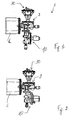
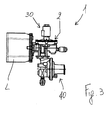
- FIG. 3 shows a shut-off unit comprising a remote-control trigger device and a pressure-switch trigger device
- FIG. 4 shows a cross-section of the shut-off unit of figure 1 , comprising an inertial trigger device and a remote-control trigger device;
- FIG. 5 shows a cross-section of the shut-off unit of figure 3 , comprising a remote-control trigger device and a pressure-switch trigger device.
- reference numeral 1 globally denotes a shut-off unit according to the present invention.
- Unit 1 comprises an obturator device able to move from an open configuration in which the transit of fluid from the input pipe to the output pipe is allowed, to a closed configuration in which said transit is impeded.
- the obturator device comprises a main body 2a, able to be joined to the input pipe 4 and the output pipe 6 of a distribution line L of a fluid, for example of gas.
- the obturator device also comprises a shaft 8 extending mainly along a shaft axis X, supported in a translatable manner inside the main body. Specifically, the shaft can be translated from a closed position, in which the obturator device is in the closed configuration, to an open position, in which the obturator device is in the open configuration.
- the obturator device comprises, in addition, an obturator 10, for example discoid and fitted with seals, positioned at the head of the shaft, so as to close off the fluidic communication between the input pipe and the output pipe when the device is in the closed configuration.
- an obturator 10 for example discoid and fitted with seals, positioned at the head of the shaft, so as to close off the fluidic communication between the input pipe and the output pipe when the device is in the closed configuration.
- the obturator device comprises activators able to act on the shaft 8 so as to move it from the open position to the closed position; for example, the activators comprise an elastic element 14, placed in compression between the shaft 8 and the main body 2a to push the shaft from the open position to the closed position.
- the obturator device comprises means of retention able to keep the shaft 8 in the open position, in contrast with said activators.
- the means of retention comprise a supporting body 16, moving in translation, and a lever 18, hinged to the supporting body 16, suitable for rotation from an engaged position, in which it is engaged with the shaft 8 so as to retain it, to a release position, in which it does not retain the shaft 8.
- the means of retention comprise, moreover, a pin 20, mobile in translation in the lever 18, directly engaged on the shaft 8 in the engaged position of the lever, and a spring 22, compressed between the pin 20 and the lever 18, able to constantly influence the lever to move it from the engaged position to the release position.
- the means of retention comprise a cam element 24, able to pass from an engaged position, in which it influences the lever keeping it in its engaged position, to a release position, in which it does not retain the lever, thus free to pass to the release position.
- the shut-off unit also comprises a first trigger device 30, able to act on said obturator device, to move it from the open configuration to the closed configuration.
- the first trigger device is chosen from the group comprising inertial, remote-control, and pressure switch devices.
- the shut-off unit comprises a second trigger device 40, able to act on said obturator device, to move it from the open configuration to the closed configuration.
- the second trigger device different from the first, is also chosen from the group comprising inertial, remote-control, and pressure switch devices.
- the first and second trigger devices are both mounted on the main body 2a of the obturator device and, specifically, are able to co-operate with the shaft 8 to enable the obturator device to pass from the open to the closed configuration.
- the first trigger device 30 can engage with the lever 18 of the means of retention and the second trigger device 40 can engage with the supporting body 16, to disactivate the means of retention.
- first trigger device 30 is joined to the cam element 24.
- the inertial trigger device comprises a rocker arm 50 able to oscillate and a first trigger shaft 52, able to be influenced by the oscillating rocker arm and engaged with the obturator device o keep it in the open configuration, as well as to disengage from it by means of the rocker arm.
- first trigger shaft 52 is joined to the cam element 24, positioned at the head of it.
- the first trigger shaft can engage with the supporting body 16 of the means of retention so as to disactivate it.
- the remotely-controlled trigger device comprises an actuator 60 which moves on receipt of an electric or radio signal and a second trigger shaft 62, which may be influenced by the actuator, engaged with the obturator device to keep it in the open position.
- the second trigger shaft 62 may be engaged with the means of retention, for example, to the supporting body 16 of it, so as to disactivate it and allow the movement of the shaft 8 to the closed position.
- the second trigger shaft 62 is joined to the cam element 24.
- the pressure-switch trigger device comprises a flexible membrane 70 which defines a pressure chamber 72 inside the body of the device in fluidic communication with the distribution line L so as to be sensitive to the pressure of the fluid, and a third trigger shaft 74, engaged with the obturator device to keep it in the open configuration.
- the third trigger shaft 74 can engage with the means of retention, for example with the supporting body 16 of it, to disactivate it.
- the third trigger shaft 74 is joined to the cam element 24 situated at the head of the same.
- the shaft is disengaged from the means of retention and shuts off the transit of fluid both when the entity of the oscillations is such as to activate the inertial device, and when such tremors are detected by an accelerometer, connected to the actuator.
- a shut-off unit comprising an inertial trigger device and a pressure switch trigger device
- the shaft is disengaged and shuts off the transit of fluid both when the entity of the oscillations is such as to activate the inertial device, and when an excessive reduction or excessive increase in the pressure of the fluid occurs, for example as a result of damage to the distribution line.
- a shut-off unit comprising a remotely-controlled trigger device and a pressure-switch trigger device
- the shaft is disengaged and shuts off the transit of fluid both when the entity of the oscillations is detected by an accelerometer connected to the actuator, and when an excessive reduction or excessive increase in the pressure of the fluid occurs, for example as a result of damage to the distribution line.
- the shut-off unit according to the present invention is extremely reliable, in that the shutting-off of the line follows the occurrence of causes independent of each other.
Landscapes
- Engineering & Computer Science (AREA)
- General Engineering & Computer Science (AREA)
- Mechanical Engineering (AREA)
- Feeding And Controlling Fuel (AREA)
- Regulation And Control Of Combustion (AREA)
- Control Of Combustion (AREA)
- Gas Separation By Absorption (AREA)
- Filling Or Discharging Of Gas Storage Vessels (AREA)
- Catching Or Destruction (AREA)
Applications Claiming Priority (1)
| Application Number | Priority Date | Filing Date | Title |
|---|---|---|---|
| IT000172A ITBS20070172A1 (it) | 2007-11-08 | 2007-11-08 | Gruppo di intercettazione di un fluido, ad esempio gas, a duplice innesco |
Related Parent Applications (1)
| Application Number | Title | Priority Date | Filing Date |
|---|---|---|---|
| ITBS20070172 Previously-Filed-Application | 2007-11-08 |
Publications (3)
| Publication Number | Publication Date |
|---|---|
| EP2058569A2 true EP2058569A2 (de) | 2009-05-13 |
| EP2058569A3 EP2058569A3 (de) | 2010-01-20 |
| EP2058569B1 EP2058569B1 (de) | 2011-10-19 |
Family
ID=40314555
Family Applications (1)
| Application Number | Title | Priority Date | Filing Date |
|---|---|---|---|
| EP07425839A Active EP2058569B1 (de) | 2007-11-08 | 2007-12-31 | Schließeinheit für eine Flüssigkeit, wie z.B. Gas, mit doppeltem Auslöser |
Country Status (4)
| Country | Link |
|---|---|
| EP (1) | EP2058569B1 (de) |
| AT (1) | ATE529678T1 (de) |
| ES (1) | ES2373924T3 (de) |
| IT (1) | ITBS20070172A1 (de) |
Cited By (2)
| Publication number | Priority date | Publication date | Assignee | Title |
|---|---|---|---|---|
| EP2497984A1 (de) * | 2011-03-08 | 2012-09-12 | Tyczka Totalgaz GmbH | Sicherheitsabsperrventil und Verfahren zum Absperren einer Gasleitung |
| ITUB20152323A1 (it) * | 2015-07-20 | 2017-01-20 | Pietro Fiorentini Spa | Valvola di blocco per gas e metodo di realizzazione di tale valvola di blocco |
Citations (1)
| Publication number | Priority date | Publication date | Assignee | Title |
|---|---|---|---|---|
| IT1303464B1 (it) | 1998-11-24 | 2000-11-06 | Fiorentini Minireg S P A | Valvola di blocco di bassa e alta pressione |
Family Cites Families (1)
| Publication number | Priority date | Publication date | Assignee | Title |
|---|---|---|---|---|
| US5960807A (en) * | 1998-05-05 | 1999-10-05 | Reyman; Mark | Vibration and flow actuated valve shutoff system |
-
2007
- 2007-11-08 IT IT000172A patent/ITBS20070172A1/it unknown
- 2007-12-31 EP EP07425839A patent/EP2058569B1/de active Active
- 2007-12-31 AT AT07425839T patent/ATE529678T1/de not_active IP Right Cessation
- 2007-12-31 ES ES07425839T patent/ES2373924T3/es active Active
Patent Citations (1)
| Publication number | Priority date | Publication date | Assignee | Title |
|---|---|---|---|---|
| IT1303464B1 (it) | 1998-11-24 | 2000-11-06 | Fiorentini Minireg S P A | Valvola di blocco di bassa e alta pressione |
Cited By (2)
| Publication number | Priority date | Publication date | Assignee | Title |
|---|---|---|---|---|
| EP2497984A1 (de) * | 2011-03-08 | 2012-09-12 | Tyczka Totalgaz GmbH | Sicherheitsabsperrventil und Verfahren zum Absperren einer Gasleitung |
| ITUB20152323A1 (it) * | 2015-07-20 | 2017-01-20 | Pietro Fiorentini Spa | Valvola di blocco per gas e metodo di realizzazione di tale valvola di blocco |
Also Published As
| Publication number | Publication date |
|---|---|
| ITBS20070172A1 (it) | 2009-05-09 |
| ES2373924T3 (es) | 2012-02-10 |
| EP2058569A3 (de) | 2010-01-20 |
| ATE529678T1 (de) | 2011-11-15 |
| EP2058569B1 (de) | 2011-10-19 |
Similar Documents
| Publication | Publication Date | Title |
|---|---|---|
| WO2008131153A3 (en) | Slam shut safety device | |
| CN205371730U (zh) | 超压时由压杆失稳触发动作的自动阀门 | |
| RU2012144285A (ru) | Клапан подземной скважины, приводимый в действие за счет дифференциального давления | |
| EP0275155B1 (de) | Leckanzeiger | |
| MY167547A (en) | A safety mechanism for a well, a well comprising the safety mechanism, and related methods | |
| EP2058569B1 (de) | Schließeinheit für eine Flüssigkeit, wie z.B. Gas, mit doppeltem Auslöser | |
| KR20120091574A (ko) | 방화형 도어클로저 | |
| CN214171436U (zh) | 一种切断阀 | |
| US6789566B1 (en) | Safety contrivance for gas-using device | |
| CN108825833A (zh) | 一种带有隔离装置的阀门系统 | |
| US3892258A (en) | High pressure safety valve | |
| US4782848A (en) | Shock actuated device | |
| WO2021056613A1 (zh) | 可快速自动关闭的装置及天然气井口紧急切断装置 | |
| RU16024U1 (ru) | Автомат аварийного закрытия запорной арматуры магистрального газопровода | |
| JP2007327584A (ja) | 流水検知装置 | |
| KR200472437Y1 (ko) | 알람밸브 | |
| GB2363330A (en) | Air pressure stabilising device | |
| JP4796898B2 (ja) | 流水検知装置 | |
| CN105443815A (zh) | 膜片辅助式压杆失稳触发型的自动阀门 | |
| CN107940071A (zh) | 应急自动控制电动执行器 | |
| WO2011028191A2 (en) | Mechanical earthquake valve with orifice shut off | |
| CN207486146U (zh) | 安全切断阀及其控制系统 | |
| US3262323A (en) | Control device | |
| CN113057090A (zh) | 一种控制方法、装置、闸阀及存储介质 | |
| US3262322A (en) | Control device |
Legal Events
| Date | Code | Title | Description |
|---|---|---|---|
| PUAI | Public reference made under article 153(3) epc to a published international application that has entered the european phase |
Free format text: ORIGINAL CODE: 0009012 |
|
| AK | Designated contracting states |
Kind code of ref document: A2 Designated state(s): AT BE BG CH CY CZ DE DK EE ES FI FR GB GR HU IE IS IT LI LT LU LV MC MT NL PL PT RO SE SI SK TR |
|
| AX | Request for extension of the european patent |
Extension state: AL BA HR MK RS |
|
| PUAL | Search report despatched |
Free format text: ORIGINAL CODE: 0009013 |
|
| AK | Designated contracting states |
Kind code of ref document: A3 Designated state(s): AT BE BG CH CY CZ DE DK EE ES FI FR GB GR HU IE IS IT LI LT LU LV MC MT NL PL PT RO SE SI SK TR |
|
| AX | Request for extension of the european patent |
Extension state: AL BA HR MK RS |
|
| 17P | Request for examination filed |
Effective date: 20100218 |
|
| 17Q | First examination report despatched |
Effective date: 20100317 |
|
| RAP1 | Party data changed (applicant data changed or rights of an application transferred) |
Owner name: PIETRO FIORENTINI S.P.A. |
|
| AKX | Designation fees paid |
Designated state(s): AT BE BG CH CY CZ DE DK EE ES FI FR GB GR HU IE IS IT LI LT LU LV MC MT NL PL PT RO SE SI SK TR |
|
| GRAP | Despatch of communication of intention to grant a patent |
Free format text: ORIGINAL CODE: EPIDOSNIGR1 |
|
| GRAS | Grant fee paid |
Free format text: ORIGINAL CODE: EPIDOSNIGR3 |
|
| GRAA | (expected) grant |
Free format text: ORIGINAL CODE: 0009210 |
|
| AK | Designated contracting states |
Kind code of ref document: B1 Designated state(s): AT BE BG CH CY CZ DE DK EE ES FI FR GB GR HU IE IS IT LI LT LU LV MC MT NL PL PT RO SE SI SK TR |
|
| REG | Reference to a national code |
Ref country code: GB Ref legal event code: FG4D |
|
| REG | Reference to a national code |
Ref country code: CH Ref legal event code: EP |
|
| REG | Reference to a national code |
Ref country code: IE Ref legal event code: FG4D |
|
| REG | Reference to a national code |
Ref country code: DE Ref legal event code: R096 Ref document number: 602007018020 Country of ref document: DE Effective date: 20120112 |
|
| REG | Reference to a national code |
Ref country code: NL Ref legal event code: VDEP Effective date: 20111019 |
|
| REG | Reference to a national code |
Ref country code: ES Ref legal event code: FG2A Ref document number: 2373924 Country of ref document: ES Kind code of ref document: T3 Effective date: 20120210 |
|
| LTIE | Lt: invalidation of european patent or patent extension |
Effective date: 20111019 |
|
| REG | Reference to a national code |
Ref country code: AT Ref legal event code: MK05 Ref document number: 529678 Country of ref document: AT Kind code of ref document: T Effective date: 20111019 |
|
| PG25 | Lapsed in a contracting state [announced via postgrant information from national office to epo] |
Ref country code: LT Free format text: LAPSE BECAUSE OF FAILURE TO SUBMIT A TRANSLATION OF THE DESCRIPTION OR TO PAY THE FEE WITHIN THE PRESCRIBED TIME-LIMIT Effective date: 20111019 Ref country code: IS Free format text: LAPSE BECAUSE OF FAILURE TO SUBMIT A TRANSLATION OF THE DESCRIPTION OR TO PAY THE FEE WITHIN THE PRESCRIBED TIME-LIMIT Effective date: 20120219 Ref country code: BE Free format text: LAPSE BECAUSE OF FAILURE TO SUBMIT A TRANSLATION OF THE DESCRIPTION OR TO PAY THE FEE WITHIN THE PRESCRIBED TIME-LIMIT Effective date: 20111019 |
|
| PG25 | Lapsed in a contracting state [announced via postgrant information from national office to epo] |
Ref country code: NL Free format text: LAPSE BECAUSE OF FAILURE TO SUBMIT A TRANSLATION OF THE DESCRIPTION OR TO PAY THE FEE WITHIN THE PRESCRIBED TIME-LIMIT Effective date: 20111019 Ref country code: PT Free format text: LAPSE BECAUSE OF FAILURE TO SUBMIT A TRANSLATION OF THE DESCRIPTION OR TO PAY THE FEE WITHIN THE PRESCRIBED TIME-LIMIT Effective date: 20120220 Ref country code: GR Free format text: LAPSE BECAUSE OF FAILURE TO SUBMIT A TRANSLATION OF THE DESCRIPTION OR TO PAY THE FEE WITHIN THE PRESCRIBED TIME-LIMIT Effective date: 20120120 Ref country code: SE Free format text: LAPSE BECAUSE OF FAILURE TO SUBMIT A TRANSLATION OF THE DESCRIPTION OR TO PAY THE FEE WITHIN THE PRESCRIBED TIME-LIMIT Effective date: 20111019 Ref country code: LV Free format text: LAPSE BECAUSE OF FAILURE TO SUBMIT A TRANSLATION OF THE DESCRIPTION OR TO PAY THE FEE WITHIN THE PRESCRIBED TIME-LIMIT Effective date: 20111019 Ref country code: SI Free format text: LAPSE BECAUSE OF FAILURE TO SUBMIT A TRANSLATION OF THE DESCRIPTION OR TO PAY THE FEE WITHIN THE PRESCRIBED TIME-LIMIT Effective date: 20111019 |
|
| PG25 | Lapsed in a contracting state [announced via postgrant information from national office to epo] |
Ref country code: CY Free format text: LAPSE BECAUSE OF FAILURE TO SUBMIT A TRANSLATION OF THE DESCRIPTION OR TO PAY THE FEE WITHIN THE PRESCRIBED TIME-LIMIT Effective date: 20111019 |
|
| PG25 | Lapsed in a contracting state [announced via postgrant information from national office to epo] |
Ref country code: BG Free format text: LAPSE BECAUSE OF FAILURE TO SUBMIT A TRANSLATION OF THE DESCRIPTION OR TO PAY THE FEE WITHIN THE PRESCRIBED TIME-LIMIT Effective date: 20120119 Ref country code: EE Free format text: LAPSE BECAUSE OF FAILURE TO SUBMIT A TRANSLATION OF THE DESCRIPTION OR TO PAY THE FEE WITHIN THE PRESCRIBED TIME-LIMIT Effective date: 20111019 Ref country code: MC Free format text: LAPSE BECAUSE OF NON-PAYMENT OF DUE FEES Effective date: 20111231 Ref country code: SK Free format text: LAPSE BECAUSE OF FAILURE TO SUBMIT A TRANSLATION OF THE DESCRIPTION OR TO PAY THE FEE WITHIN THE PRESCRIBED TIME-LIMIT Effective date: 20111019 Ref country code: CZ Free format text: LAPSE BECAUSE OF FAILURE TO SUBMIT A TRANSLATION OF THE DESCRIPTION OR TO PAY THE FEE WITHIN THE PRESCRIBED TIME-LIMIT Effective date: 20111019 Ref country code: DK Free format text: LAPSE BECAUSE OF FAILURE TO SUBMIT A TRANSLATION OF THE DESCRIPTION OR TO PAY THE FEE WITHIN THE PRESCRIBED TIME-LIMIT Effective date: 20111019 |
|
| REG | Reference to a national code |
Ref country code: CH Ref legal event code: PL |
|
| PLBE | No opposition filed within time limit |
Free format text: ORIGINAL CODE: 0009261 |
|
| STAA | Information on the status of an ep patent application or granted ep patent |
Free format text: STATUS: NO OPPOSITION FILED WITHIN TIME LIMIT |
|
| PG25 | Lapsed in a contracting state [announced via postgrant information from national office to epo] |
Ref country code: RO Free format text: LAPSE BECAUSE OF FAILURE TO SUBMIT A TRANSLATION OF THE DESCRIPTION OR TO PAY THE FEE WITHIN THE PRESCRIBED TIME-LIMIT Effective date: 20111019 Ref country code: IT Free format text: LAPSE BECAUSE OF FAILURE TO SUBMIT A TRANSLATION OF THE DESCRIPTION OR TO PAY THE FEE WITHIN THE PRESCRIBED TIME-LIMIT Effective date: 20111019 Ref country code: PL Free format text: LAPSE BECAUSE OF FAILURE TO SUBMIT A TRANSLATION OF THE DESCRIPTION OR TO PAY THE FEE WITHIN THE PRESCRIBED TIME-LIMIT Effective date: 20111019 |
|
| REG | Reference to a national code |
Ref country code: FR Ref legal event code: ST Effective date: 20120831 |
|
| 26N | No opposition filed |
Effective date: 20120720 |
|
| GBPC | Gb: european patent ceased through non-payment of renewal fee |
Effective date: 20120119 |
|
| REG | Reference to a national code |
Ref country code: IE Ref legal event code: MM4A |
|
| REG | Reference to a national code |
Ref country code: DE Ref legal event code: R119 Ref document number: 602007018020 Country of ref document: DE Effective date: 20120703 |
|
| PG25 | Lapsed in a contracting state [announced via postgrant information from national office to epo] |
Ref country code: CH Free format text: LAPSE BECAUSE OF NON-PAYMENT OF DUE FEES Effective date: 20111231 Ref country code: DE Free format text: LAPSE BECAUSE OF NON-PAYMENT OF DUE FEES Effective date: 20120703 Ref country code: GB Free format text: LAPSE BECAUSE OF NON-PAYMENT OF DUE FEES Effective date: 20120119 Ref country code: LI Free format text: LAPSE BECAUSE OF NON-PAYMENT OF DUE FEES Effective date: 20111231 Ref country code: IE Free format text: LAPSE BECAUSE OF NON-PAYMENT OF DUE FEES Effective date: 20111231 |
|
| PG25 | Lapsed in a contracting state [announced via postgrant information from national office to epo] |
Ref country code: AT Free format text: LAPSE BECAUSE OF FAILURE TO SUBMIT A TRANSLATION OF THE DESCRIPTION OR TO PAY THE FEE WITHIN THE PRESCRIBED TIME-LIMIT Effective date: 20111019 |
|
| PG25 | Lapsed in a contracting state [announced via postgrant information from national office to epo] |
Ref country code: MT Free format text: LAPSE BECAUSE OF FAILURE TO SUBMIT A TRANSLATION OF THE DESCRIPTION OR TO PAY THE FEE WITHIN THE PRESCRIBED TIME-LIMIT Effective date: 20111019 |
|
| PG25 | Lapsed in a contracting state [announced via postgrant information from national office to epo] |
Ref country code: FR Free format text: LAPSE BECAUSE OF NON-PAYMENT OF DUE FEES Effective date: 20120102 |
|
| PG25 | Lapsed in a contracting state [announced via postgrant information from national office to epo] |
Ref country code: LU Free format text: LAPSE BECAUSE OF NON-PAYMENT OF DUE FEES Effective date: 20111231 |
|
| PG25 | Lapsed in a contracting state [announced via postgrant information from national office to epo] |
Ref country code: FI Free format text: LAPSE BECAUSE OF FAILURE TO SUBMIT A TRANSLATION OF THE DESCRIPTION OR TO PAY THE FEE WITHIN THE PRESCRIBED TIME-LIMIT Effective date: 20111019 |
|
| PG25 | Lapsed in a contracting state [announced via postgrant information from national office to epo] |
Ref country code: HU Free format text: LAPSE BECAUSE OF FAILURE TO SUBMIT A TRANSLATION OF THE DESCRIPTION OR TO PAY THE FEE WITHIN THE PRESCRIBED TIME-LIMIT Effective date: 20111019 |
|
| PGFP | Annual fee paid to national office [announced via postgrant information from national office to epo] |
Ref country code: TR Payment date: 20221226 Year of fee payment: 16 Ref country code: ES Payment date: 20230224 Year of fee payment: 16 |
|
| REG | Reference to a national code |
Ref country code: ES Ref legal event code: FD2A Effective date: 20250204 |
|
| PG25 | Lapsed in a contracting state [announced via postgrant information from national office to epo] |
Ref country code: ES Free format text: LAPSE BECAUSE OF NON-PAYMENT OF DUE FEES Effective date: 20240101 |