EP2058577A2 - Teleskopisch einstellbare Klemme - Google Patents
Teleskopisch einstellbare Klemme Download PDFInfo
- Publication number
- EP2058577A2 EP2058577A2 EP08168629A EP08168629A EP2058577A2 EP 2058577 A2 EP2058577 A2 EP 2058577A2 EP 08168629 A EP08168629 A EP 08168629A EP 08168629 A EP08168629 A EP 08168629A EP 2058577 A2 EP2058577 A2 EP 2058577A2
- Authority
- EP
- European Patent Office
- Prior art keywords
- positioning
- anchor rod
- clamp
- set forth
- clamping
- Prior art date
- Legal status (The legal status is an assumption and is not a legal conclusion. Google has not performed a legal analysis and makes no representation as to the accuracy of the status listed.)
- Withdrawn
Links
- 230000004888 barrier function Effects 0.000 claims abstract description 13
- 230000006835 compression Effects 0.000 claims description 12
- 238000007906 compression Methods 0.000 claims description 12
- 239000004033 plastic Substances 0.000 claims description 5
- 229920003023 plastic Polymers 0.000 claims description 5
- 230000015572 biosynthetic process Effects 0.000 claims description 4
- 230000000717 retained effect Effects 0.000 claims description 4
- 239000000645 desinfectant Substances 0.000 claims description 3
- 239000000463 material Substances 0.000 claims description 3
- 239000011347 resin Substances 0.000 claims description 3
- 229920005989 resin Polymers 0.000 claims description 3
- 229920000443 Xenoy Polymers 0.000 description 2
- 239000000853 adhesive Substances 0.000 description 2
- 230000001070 adhesive effect Effects 0.000 description 2
- 239000002184 metal Substances 0.000 description 2
- 238000000034 method Methods 0.000 description 2
- 229910001220 stainless steel Inorganic materials 0.000 description 2
- 239000010935 stainless steel Substances 0.000 description 2
- 230000009286 beneficial effect Effects 0.000 description 1
- 230000017531 blood circulation Effects 0.000 description 1
- 238000005266 casting Methods 0.000 description 1
- 125000004122 cyclic group Chemical group 0.000 description 1
- 238000003754 machining Methods 0.000 description 1
- 239000000203 mixture Substances 0.000 description 1
- 229920000515 polycarbonate Polymers 0.000 description 1
- 239000004417 polycarbonate Substances 0.000 description 1
- 229920000728 polyester Polymers 0.000 description 1
- 238000002560 therapeutic procedure Methods 0.000 description 1
Images




Classifications
-
- F—MECHANICAL ENGINEERING; LIGHTING; HEATING; WEAPONS; BLASTING
- F16—ENGINEERING ELEMENTS AND UNITS; GENERAL MEASURES FOR PRODUCING AND MAINTAINING EFFECTIVE FUNCTIONING OF MACHINES OR INSTALLATIONS; THERMAL INSULATION IN GENERAL
- F16B—DEVICES FOR FASTENING OR SECURING CONSTRUCTIONAL ELEMENTS OR MACHINE PARTS TOGETHER, e.g. NAILS, BOLTS, CIRCLIPS, CLAMPS, CLIPS OR WEDGES; JOINTS OR JOINTING
- F16B7/00—Connections of rods or tubes, e.g. of non-circular section, mutually, including resilient connections
- F16B7/10—Telescoping systems
- F16B7/105—Telescoping systems locking in discrete positions, e.g. in extreme extended position
-
- A—HUMAN NECESSITIES
- A61—MEDICAL OR VETERINARY SCIENCE; HYGIENE
- A61M—DEVICES FOR INTRODUCING MEDIA INTO, OR ONTO, THE BODY; DEVICES FOR TRANSDUCING BODY MEDIA OR FOR TAKING MEDIA FROM THE BODY; DEVICES FOR PRODUCING OR ENDING SLEEP OR STUPOR
- A61M5/00—Devices for bringing media into the body in a subcutaneous, intra-vascular or intramuscular way; Accessories therefor, e.g. filling or cleaning devices, arm-rests
- A61M5/14—Infusion devices, e.g. infusing by gravity; Blood infusion; Accessories therefor
- A61M5/1414—Hanging-up devices
-
- F—MECHANICAL ENGINEERING; LIGHTING; HEATING; WEAPONS; BLASTING
- F16—ENGINEERING ELEMENTS AND UNITS; GENERAL MEASURES FOR PRODUCING AND MAINTAINING EFFECTIVE FUNCTIONING OF MACHINES OR INSTALLATIONS; THERMAL INSULATION IN GENERAL
- F16B—DEVICES FOR FASTENING OR SECURING CONSTRUCTIONAL ELEMENTS OR MACHINE PARTS TOGETHER, e.g. NAILS, BOLTS, CIRCLIPS, CLAMPS, CLIPS OR WEDGES; JOINTS OR JOINTING
- F16B2/00—Friction-grip releasable fastenings
- F16B2/02—Clamps, i.e. with gripping action effected by positive means other than the inherent resistance to deformation of the material of the fastening
- F16B2/06—Clamps, i.e. with gripping action effected by positive means other than the inherent resistance to deformation of the material of the fastening external, i.e. with contracting action
-
- F—MECHANICAL ENGINEERING; LIGHTING; HEATING; WEAPONS; BLASTING
- F16—ENGINEERING ELEMENTS AND UNITS; GENERAL MEASURES FOR PRODUCING AND MAINTAINING EFFECTIVE FUNCTIONING OF MACHINES OR INSTALLATIONS; THERMAL INSULATION IN GENERAL
- F16M—FRAMES, CASINGS OR BEDS OF ENGINES, MACHINES OR APPARATUS, NOT SPECIFIC TO ENGINES, MACHINES OR APPARATUS PROVIDED FOR ELSEWHERE; STANDS; SUPPORTS
- F16M13/00—Other supports for positioning apparatus or articles; Means for steadying hand-held apparatus or articles
- F16M13/02—Other supports for positioning apparatus or articles; Means for steadying hand-held apparatus or articles for supporting on, or attaching to, an object, e.g. tree, gate, window-frame, cycle
- F16M13/022—Other supports for positioning apparatus or articles; Means for steadying hand-held apparatus or articles for supporting on, or attaching to, an object, e.g. tree, gate, window-frame, cycle repositionable
Definitions
- This invention relates to an apparatus for securing an object to a support, particularly for securing a controller of a sequential compression device to a support.
- Compression of a body part, such as a leg is beneficial to persons who have blood circulation problems, specifically poor venous return to the heart.
- Compression therapy devices on the market today use one or more pneumatic bladders that encircle the legs and/or feet to apply cyclic compression.
- the bladders are inflated in a predetermined order, to prescribed pressures and for predetermined time intervals.
- a controller that operates the inflation normally employs an air pump and valves that operate to direct flow of the air to the bladders.
- the controller is located remotely from the bladders, such as on the footboard of a bed, on the floor or on a night stand.
- a bed-hook is attached to the controller for securing the controller to a footboard.
- One previous bed-hook design includes a roughly U-shaped rod that is attached at both ends to the rear of the controller.
- the rod extends outward and is bent downward from the rear of the controller forming a hook.
- the top of the footboard can be positioned between the controller and the downwardly bent portion of the rod. Because footboards can vary in width and because the looped rod is rigid and can not be adjusted, the controller may not always be securely fixed to the footboard.
- Another bed-hook design includes two arms which are pivotally attached to the controller. To secure the controller to the footboard of a bed, the arms are swung outwardly from the controller and the footboard is positioned in the space between the arms and the controller.
- the anchor rod is adapted for affixation to the object at the first end portion of the anchor rod and includes a plurality of axially spaced, circumferentially extending grooves formed in the anchor rod.
- the grooves define at least one barrier wall between adjacent grooves.
- the clamp includes a positioning member that defines a receptacle sized and shaped to receive at least the second end portion of the anchor rod and allows motion of the anchor rod relative to the positioning member in the receptacle.
- the positioning member comprises a positioning tab that projects into the receptacle and is sized and shaped to be received in one of the grooves and retained in said one groove by the barrier wall. At least one of the positioning tab and the barrier wall is resiliently deflectable upon application of a release force along the longitudinal axis of the anchor rod for moving the positioning tab out of one of the grooves.
- the clamp includes a clamping member supported by the positioning member that extends generally radially outwardly from the longitudinal axis of the anchor rod. Relative movement of the anchor rod and the positioning member changes the distance between the clamping member and the first end portion of the anchor rod for clamping the object to the support.
- a clamp for securing an object to a support generally comprises a pair of anchor rods each having a longitudinal axis and is adapted for affixation to the object.
- the clamp includes positioning members each receiving a respective one of the anchor rods in sliding relation with the positioning member and clamping members each connected to a respective one of the positioning members for conjoint movement with the positioning members relative to the anchor rods.
- the clamping members extend generally radially outwardly from the longitudinal axes of the anchor rods.
- the clamp includes a grip member connected to the positioning members and the clamping members that spaces the positioning members.
- the grip member is sized for being gripped in the hand and has a curved contour.
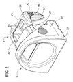
- Fig. 1 is a perspective of a clamp and a controller of a sequential compression device
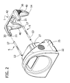
- Fig. 2 is an exploded perspective of the clamp and controller of Fig. 1 ;
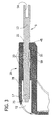
- Fig. 3 is an enlarged fragmentary section of the clamp
- Fig. 4 is a partial section of the clamp and controller with the clamp in a position nearest the controller;
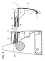
- Fig. 5 is the section of Fig. 4 , but with the clamp in a position farthest the controller;
- Fig. 6 is a rear perspective of the positioning member of the clamp of Fig. 1 ;
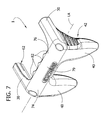
- Fig. 7 is a front perspective of the positioning member of Fig. 1 ;
- Fig. 8 is a side elevation of a controller of a sequential compression device and another embodiment of the clamp
- Fig. 9 is a rear perspective of still another embodiment of the clamp.
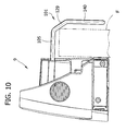
- Fig. 10 is a side elevation of a controller of a sequential compression device incorporating the clamp of Fig. 9 ;
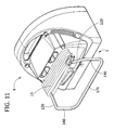
- Fig. 11 is a rear perspective of the controller and clamp shown in Fig 10 with the power cord wrapped around the clamp for storage of the controller and clamp.
- a clamp constructed according to the principles of the present invention is generally indicated at 1.
- the clamp 1 is suitable for securing an object to a support and is particularly well-suited for securing a controller 9 of a sequential compression device to, for example, a footboard, headboard or siderail of a medical bed. While the clamp herein is shown as supporting a controller of a sequential compression device, it will be appreciated that the clamp is capable of securing a variety of objects including, for example, various other medical apparatus or non-medical apparatus.
- the controller 9 includes a faceplate 22 and main body 25.
- the controller 9 is shown with the clamp 1 exploded therefrom in Fig. 2 .
- the new clamp 1 is telescopingly adjustable such that the controller can be securely fixed to supports having a variety of widths.
- the clamp includes a pair of anchor rods 5, each defining a longitudinal axis.
- the number of anchor rods may be greater or fewer than two within the scope of the present invention.
- Each anchor rod 5 has a first end portion 13 that is adapted to be affixed to the main body 25 of the controller 9.
- the first end portion 13 of each rod 5 may be affixed by, for example, adhesive, a bolt and nut, or a screw.
- each anchor rod 5 is secured to the main body 25 by a bolt 26 received in a threaded opening 5a of the anchor rod ( Fig. 4 ).
- the first end portion 13 or entire anchor rod 5 may be integral with the controller body 25.
- Each anchor rod 5 includes a second end portion 17.
- the anchor rod 5 may be constructed of metal and, preferably, stainless steel.
- the clamp 1 includes a pair of positioning members shown generally at 30. Each positioning member 30 defines a receptacle 21.
- the receptacle 21 is sized and shaped to receive the second end portion 17 of one anchor rod 5.
- the second end portion 17 of the anchor rod 5 is not affixed to the positioning member 30 but, rather, is capable of movement relative to the positioning member in the receptacle 21.
- the positioning members 30 support a clamping member 42.
- the clamping member 42 extends generally radially outwardly from the longitudinal axis of each respective anchor rod 5.
- the positioning member 30 may be affixed to the clamping member by, for example, adhesive, nut and bolts, screws, and tongue and groove.
- the positioning member 30 and clamping member 42 are molded as one piece.
- the clamping member 42 includes a pair of spaced apart legs 40 that project generally radially from the longitudinal axis of the anchor rods 5.
- each leg 40 may include a strip of frictionalizing material, for example rubber, to assist in gripping the support.
- a strip of rubber 14 is located on the back edges of the legs 40.
- the strip 14 extends continuously from one leg 40 to the other. It will be understood that other configurations with respect to the strip are within the scope of the present invention, such as plural, spaced apart strips.
- the positioning member 30 and legs 40 may be molded of plastic and, optionally, a resin that is chemically compatible with disinfectants and cleansers used in a hospital setting such as, for example, XENOY, a blend of semi-crystalline polyester and polycarbonate commercially available from GE Plastics (Pittsfield, MA).
- a plurality of axially spaced circumferentially extending grooves 33 are formed within the anchor rod 5.
- the grooves 33 define a pair of barrier walls 35 that separate the grooves.
- Each positioning member 30 includes a positioning tab 45 sized and shaped to fit within the respective circumferential grooves 33 and to be retained in a groove (at least in part) by the barrier wall 35.
- the positioning tab 45 may be resiliently deflectable so that upon application of a sufficient force along the longitudinal axis of the anchor rod 5 the positioning tab moves out of its groove 33 and relocates in another groove thereby creating a change in distance between the controller 9 and the legs 40 of the clamping member 42. While the clamp is shown with a pair of positioning tabs 45, only one tab is required for the clamp to properly extend and retract.
- the grooves 33 may be formed within the anchor rod 5 during casting of the anchor rod or may be formed later by machining.
- the barrier walls 35 of the anchor rod 5 are deflectable rather than the positioning tab 35.
- the receptacle 21 defined by the positioning member 30 includes a support section 59 for sliding but close contacting engagement with the anchor rod 5 on both sides of at least one of the grooves 33.
- the receptacle 21 also includes a capture section 72 for capturing the second end portion 13 of the anchor rod 5.
- the diameter of the receptacle 21 in the support section 59 is smaller than the diameter of the receptacle in the capture section 72.
- a shoulder or stop 78 ( Fig. 3 ) is defined between the support section 59 and the capture section 72.
- the second end portion 17 includes a retainer 75 that projects outwardly from the anchor rod 5 to a radius larger than the receptacle in the support section 59.
- the stop 78 limits the retainer 75 to the capture section 72 of the receptacle 21 and prevents the anchor rod 5 from decoupling from the positioning member 30.
- the clamp 1 is shown in its fully retracted position, i.e., the position with minimum distance between the legs 40 of the clamping member 42 and the controller 9.
- the clamp 1 is shown in its fully extended position in Fig. 5 , i.e., the position with maximum distance between the clamping member 42 and the controller 9.
- Fig. 5 i.e., the position with maximum distance between the clamping member 42 and the controller 9.
- each positioning member 30 includes a finger, generally indicated at 62, which is flexibly joined with the remainder of the positioning member at its base 65.
- the positioning tab 45 is located at the free end margin 67 of the finger 62. While the positioning tab 45 is located at the end of the receptacle 21 remote from the clamping member 42, it should be appreciated that the positioning tab may be generally located anywhere along the length of the anchor member 30.
- the fingers 62 deflect at the bases 65 to move the positioning tabs 45 out of the grooves 33 to adjust the position of the clamping member 42, as previously described.
- a grip member 79 sized and shaped for being gripped in the hand is attached to the pair of positioning members 30 and the legs 40 to assist in gripping the clamp 1 to hold the clamp and reposition the legs 40 relative to the controller 9.
- the legs and grip member generally form a "U" shape that allows the grip member to be gripped by a hand.
- the grip member 79 may be molded of plastic and, optionally, a resin that is chemically compatible with disinfectants and cleansers used in a hospital setting such as XENOY.
- the grip member 79 has a longitudinal axis LA and a curved contour which is curved in a direction about the longitudinal axis.
- the legs 40 taper in width toward an end which is remote from the grip member 79.
- the grip member 79 has a front 74 and a back 76.
- the back 76 of the grip member 79 forms a plurality of finger wells 82 to receive portions of the fingers of the hand.
- FIG. 8 another embodiment of the clamp 1 includes a stepped formation 86 that extends between each anchor member 30 to the clamping member 42.
- the stepped formation 86 contacts the support and allows the controller 9 and clamp 1 to be secured so that the controller is held level and allows for a tighter fit between the clamp 1 and support such as a footboard F shown in phantom.
- Figs. 9-11 illustrate another embodiment of a clamp 101 for securing an object to a support and, for example, a footboard F ( Fig. 10 ). Parts of the clamp 101 corresponding to those of the clamp 1 are given the same reference numeral, plus "100.”
- the clamp 101 includes a pair of anchor rods 105, each defining a longitudinal axis.
- the first end portion 113 of each rod 105 may be affixed to the controller body 25 in a suitable manner such as by bolts (not shown) threaded into the opening at each first end portion 113.
- a clamp (not shown) may be formed as one piece with the controller body 25.
- Each anchor rod 105 includes a second end portion 117.
- the clamp 101 includes a pair of extension members 129 that extend outward and downward from the longitudinal axes of the anchor rods 105.
- a pair of legs 140 project downward from the extension members 129.
- a crosspiece 179 is attached to the pair of legs 140 and is suitable for gripping the clamp 101.
- the anchor rod 105, extension members 129 and crosspiece 179 form a hook to attach the controller 9 to the support structure, such as the foot board F shown in Fig. 10 .
- the anchor rods 105, extension members 129, legs 140 and crosspiece 179 may be affixed by a variety of methods.
- the anchor rods 105, extension members 129, legs 140 and crosspiece 179 are formed as one piece with each other.
- the anchor rods 105, extension members 129, legs 140, and crosspiece 179 may be constructed of plastic or metal and, preferably, are constructed of stainless steel.
- the controller 9 includes a power cord 19 for providing electrical power to the controller ( Fig. 11 ).
- the power cord 19 may be wrapped around the anchor rods 105 of the clamp 101 by a practician when the controller 9 is not in use. This allows the controller 9 to be compactly stored in the hospital setting.
- the extension members 129 extend outward from the longitudinal axis of the anchor rods 105 such that the wrapped power cord becomes secured between the controller 9 and the extension rods 129. This arrangement prevents the wrapped power cord from becoming a trip hazard by sliding off the clamp and unwrapping.
Landscapes
- Engineering & Computer Science (AREA)
- General Engineering & Computer Science (AREA)
- Mechanical Engineering (AREA)
- Health & Medical Sciences (AREA)
- Vascular Medicine (AREA)
- Anesthesiology (AREA)
- Biomedical Technology (AREA)
- Heart & Thoracic Surgery (AREA)
- Hematology (AREA)
- Life Sciences & Earth Sciences (AREA)
- Animal Behavior & Ethology (AREA)
- General Health & Medical Sciences (AREA)
- Public Health (AREA)
- Veterinary Medicine (AREA)
- Clamps And Clips (AREA)
- Surgical Instruments (AREA)
- Invalid Beds And Related Equipment (AREA)
- Supports For Pipes And Cables (AREA)
Applications Claiming Priority (1)
| Application Number | Priority Date | Filing Date | Title |
|---|---|---|---|
| US11/937,176 US8246028B2 (en) | 2007-11-08 | 2007-11-08 | Telescopingly adjustable clamp |
Publications (2)
| Publication Number | Publication Date |
|---|---|
| EP2058577A2 true EP2058577A2 (de) | 2009-05-13 |
| EP2058577A3 EP2058577A3 (de) | 2011-10-05 |
Family
ID=40289360
Family Applications (1)
| Application Number | Title | Priority Date | Filing Date |
|---|---|---|---|
| EP08168629A Withdrawn EP2058577A3 (de) | 2007-11-08 | 2008-11-07 | Teleskopisch einstellbare Klemme |
Country Status (8)
| Country | Link |
|---|---|
| US (1) | US8246028B2 (de) |
| EP (1) | EP2058577A3 (de) |
| JP (1) | JP2009112822A (de) |
| CN (1) | CN101433497B (de) |
| AU (1) | AU2008243136A1 (de) |
| CA (1) | CA2642951A1 (de) |
| IL (1) | IL195119A0 (de) |
| MX (1) | MX2008014229A (de) |
Families Citing this family (31)
| Publication number | Priority date | Publication date | Assignee | Title |
|---|---|---|---|---|
| US8246028B2 (en) * | 2007-11-08 | 2012-08-21 | Tyco Healthcare Group Lp | Telescopingly adjustable clamp |
| US8133039B2 (en) * | 2009-01-26 | 2012-03-13 | Tyco Healthcare Group Lp | Mount for a compression control unit |
| USD659839S1 (en) | 2010-08-16 | 2012-05-15 | Tyco Healthcare Group Lp | Support for a pneumatic compression controller |
| USD675741S1 (en) | 2010-08-16 | 2013-02-05 | Covidien Lp | Pneumatic compression controller |
| JP2014500538A (ja) | 2010-10-12 | 2014-01-09 | タニス,ケヴィン ジェイ. | 医療機器 |
| NZ592974A (en) | 2011-05-20 | 2013-11-29 | Sullivan Andrew Laurence O | Lateral support apparatus for a chair |
| USD764654S1 (en) | 2014-03-13 | 2016-08-23 | Smith & Nephew, Inc. | Canister for collecting wound exudate |
| US9737649B2 (en) | 2013-03-14 | 2017-08-22 | Smith & Nephew, Inc. | Systems and methods for applying reduced pressure therapy |
| RU2015143724A (ru) | 2013-03-14 | 2017-04-17 | Смит Энд Нефью Инк. | Системы и способы применения терапии с использованием пониженного давления |
| JP6679483B2 (ja) | 2013-08-13 | 2020-04-15 | スミス アンド ネフュー インコーポレイテッド | 減圧治療を実施するためのシステムおよび方法 |
| TWI496050B (zh) * | 2013-08-13 | 2015-08-11 | Quanta Comp Inc | 外掛式觸控裝置 |
| WO2015138317A1 (en) | 2014-03-10 | 2015-09-17 | Stryker Corporation | Limb positioning system |
| USD764653S1 (en) | 2014-05-28 | 2016-08-23 | Smith & Nephew, Inc. | Canister for collecting wound exudate |
| USD764048S1 (en) | 2014-05-28 | 2016-08-16 | Smith & Nephew, Inc. | Device for applying negative pressure to a wound |
| USD764047S1 (en) | 2014-05-28 | 2016-08-16 | Smith & Nephew, Inc. | Therapy unit assembly |
| USD765830S1 (en) | 2014-06-02 | 2016-09-06 | Smith & Nephew, Inc. | Therapy unit assembly |
| USD770173S1 (en) | 2014-06-02 | 2016-11-01 | Smith & Nephew, Inc. | Bag |
| US10363182B2 (en) * | 2014-07-14 | 2019-07-30 | Hill-Rom Services, Inc. | Patient control arm with phone dock and head of bed lockout |
| US10188573B2 (en) | 2014-11-05 | 2019-01-29 | Allen Medical Systems, Inc. | Boot stirrup |
| US9951904B2 (en) | 2015-03-24 | 2018-04-24 | Stryker Corporation | Rotatable seat clamps for rail clamp |
| EP3520760B1 (de) | 2016-02-18 | 2020-11-04 | Hill-Rom Services, Inc. | Patientenliegevorrichtung mit integrierter gliedmassenkompressionsvorrichtung |
| DE102017000851B4 (de) * | 2017-01-31 | 2020-12-10 | Drägerwerk AG & Co. KGaA | Flexibles Konsolensystem für medizinische Geräte |
| CN107854272B (zh) * | 2017-12-07 | 2023-12-12 | 无锡圣诺亚科技有限公司 | 床杆连接器 |
| CN111281725B (zh) * | 2018-12-07 | 2021-10-08 | 上银科技股份有限公司 | 夹持机构 |
| US11033355B2 (en) * | 2018-12-31 | 2021-06-15 | Biosense Webster (Israel) Ltd. | Mounting device for medical equipment |
| CN110179519B (zh) * | 2019-06-03 | 2022-01-28 | 天津海迈医用科技有限公司 | 一种止血压脉带装置 |
| USD1050449S1 (en) * | 2020-12-10 | 2024-11-05 | Recovery Force, LLC | Docking station for compression devices |
| CN113954946B (zh) * | 2021-10-30 | 2022-08-16 | 安捷轮(福州)动力科技有限公司 | 一种中控复位脚踏及其方法 |
| USD1099288S1 (en) | 2022-03-23 | 2025-10-21 | T.J. Smith And Nephew, Limited | Device for applying negative pressure to a wound |
| WO2023178631A1 (en) * | 2022-03-25 | 2023-09-28 | Mazor Robotics Ltd. | Universal adaptor for an imaging device and corrector assembly |
| WO2024220072A1 (en) * | 2022-04-18 | 2024-10-24 | Eclipse Regenesis, Inc. | Plication systems, plication/spring systems, and methods of use thereof |
Citations (1)
| Publication number | Priority date | Publication date | Assignee | Title |
|---|---|---|---|---|
| US5876359A (en) | 1994-11-14 | 1999-03-02 | Bock; Malcolm G. | Sequential compression device controller |
Family Cites Families (127)
| Publication number | Priority date | Publication date | Assignee | Title |
|---|---|---|---|---|
| US742055A (en) * | 1903-07-01 | 1903-10-20 | Stephen Ondrey | Wrench. |
| US762762A (en) * | 1903-07-09 | 1904-06-14 | Sidney M Rowe | Wrench. |
| US878394A (en) | 1907-07-26 | 1908-02-04 | Louis Holle | Clothes-line reel. |
| US910737A (en) * | 1908-05-06 | 1909-01-26 | George W Stenz | Wrench. |
| US991602A (en) * | 1910-08-16 | 1911-05-09 | Francois C Bradley | Wrench. |
| US994070A (en) * | 1911-02-16 | 1911-05-30 | George W Fieldes | Monkey-wrench. |
| US1064361A (en) * | 1912-09-09 | 1913-06-10 | Herbert W Moak | Wrench. |
| US1181380A (en) * | 1916-02-21 | 1916-05-02 | John D Gorder | Wrench. |
| US1199806A (en) * | 1916-05-16 | 1916-10-03 | Andrew Mccallum | Wrench. |
| US1289937A (en) * | 1918-08-05 | 1918-12-31 | Anthony C Shade | Wrench. |
| US1377930A (en) * | 1919-02-04 | 1921-05-10 | L G Stallings | Wrench |
| US1612659A (en) * | 1925-01-22 | 1926-12-28 | Spangler George | Monkey wrench |
| US1643002A (en) * | 1925-05-29 | 1927-09-20 | John M Beszczak | Monkey wrench |
| US1999225A (en) * | 1932-09-27 | 1935-04-30 | Cincinnati Bickford Tool Co | Interlocked electric traverse and hydraulic clamp for mobile drills |
| US2033491A (en) | 1933-04-01 | 1936-03-10 | Hays Corp | Portable instrument |
| US2607881A (en) | 1951-04-04 | 1952-08-19 | John M Anderson | Light and mirror attachment for hospital beds |
| US2945946A (en) | 1957-07-22 | 1960-07-19 | Dillon W Moffatt | Lamp |
| US3075723A (en) | 1958-04-03 | 1963-01-29 | Leonard H Wohlfeil | Cord holder |
| FR1183959A (fr) * | 1959-02-03 | 1959-07-16 | Matériau de frottement | |
| US3030639A (en) | 1959-03-11 | 1962-04-24 | Russell I Boyer | Clamp for hospital beds |
| US3757363A (en) | 1970-09-10 | 1973-09-11 | J Langlais | Patient communicator support |
| US4101089A (en) | 1977-05-23 | 1978-07-18 | General Electric Company | Integral storage assembly for detachable power cords |
| US4262872A (en) | 1979-02-28 | 1981-04-21 | American Hospital Supply Corporation | Collapsible pole assembly |
| US4695025A (en) | 1980-02-02 | 1987-09-22 | Vaughan Thomas L | Hanger assembly |
| JPS6116479Y2 (de) | 1980-07-11 | 1986-05-21 | ||
| US4444548A (en) | 1980-08-08 | 1984-04-24 | University Testing Service Inc. | Suction apparatus |
| US4487523A (en) * | 1981-12-31 | 1984-12-11 | American Sterilizer Company | Accessory clamp for abductor bar |
| US4593422A (en) * | 1983-07-29 | 1986-06-10 | Spectro Industries, Inc. | Telescoping wing nut clamping unit |
| US4547092A (en) | 1984-02-21 | 1985-10-15 | Hamilton Industries | Accessory clamp for medical table |
| US4676687A (en) | 1984-03-09 | 1987-06-30 | Henry Koffler | Universal bedside rail clamp |
| GB2166190A (en) | 1984-07-06 | 1986-04-30 | Microsurgical Administrative S | Clamping arrangements |
| US4576501A (en) * | 1984-09-21 | 1986-03-18 | Mcconnell Bernard E | Telescoping rod clamp |
| US4627604A (en) * | 1985-04-11 | 1986-12-09 | Choi Sang B | Adjustable clamp |
| US4699344A (en) | 1985-11-01 | 1987-10-13 | Vaughan Thomas L | Support assembly |
| US4702448A (en) * | 1986-02-03 | 1987-10-27 | Lojacono Francis X | Support bracket |
| US4742981A (en) * | 1987-02-19 | 1988-05-10 | Maurice Converse | Surgical support system |
| US4796846A (en) | 1987-06-01 | 1989-01-10 | Automated Medical Products, Corporation | Retaining device for a surgical instrument |
| US4865484A (en) * | 1987-07-31 | 1989-09-12 | Mcconnell Thomas E | Single release, multiple axis coupling |
| US4832299A (en) * | 1987-12-04 | 1989-05-23 | Pacesetter Infusion, Ltd. | Clamp fixture |
| US4872224A (en) | 1988-02-16 | 1989-10-10 | Grimes Fred D | Bathtub apparatus |
| US4988062A (en) | 1988-03-10 | 1991-01-29 | London Robert A | Apparatus, system and method for organizing and maintaining a plurality of medical catheters and the like |
| US5173002A (en) * | 1988-08-01 | 1992-12-22 | Kimrick, Inc. | Lifting and positioning device for cabinets and construction panels |
| US4903922A (en) | 1988-10-31 | 1990-02-27 | Harris Iii John H | Hose holding fixture |
| US4970900A (en) | 1989-01-31 | 1990-11-20 | Baxter International, Inc. | Pole mount organizer with modular interconnection receptacles |
| US4885667A (en) | 1989-02-23 | 1989-12-05 | Boynton Selden | Gooseneck lamp and magnifier with improved clamp assembly |
| US5025780A (en) | 1989-04-26 | 1991-06-25 | Farley Daniel K | Table mounted surgical retractor |
| US5118127A (en) | 1989-11-30 | 1992-06-02 | Partington Michael J | Hitch device for interconnecting mobile apparatus in tandem |
| FR2664807A1 (fr) | 1990-07-17 | 1992-01-24 | Brehaut Gilles | Compresseur arteriel hemostatique. |
| US5033337A (en) * | 1990-11-20 | 1991-07-23 | Thomas Iii David W | Extension element for use with wrench-type hand tools |
| ITTO910188A1 (it) | 1991-03-15 | 1992-09-16 | 3T S P A | Sistema di fissaggio per componenti ed accessori di cicli |
| US5108213A (en) | 1991-03-22 | 1992-04-28 | Edgewater Medical Equipment Systems, Inc. | Clamping assembly |
| US5242240A (en) | 1991-10-17 | 1993-09-07 | Minnesota Scientific, Inc. | Clamping device for a surgical retractor |
| US6468237B1 (en) | 1991-12-17 | 2002-10-22 | Kinetic Concepts, Inc. | Pneumatic pump, housing and methods for medical purposes |
| US5163752A (en) | 1992-02-14 | 1992-11-17 | Copeland Debra L | Flashlight holder apparatus |
| US5230264A (en) * | 1992-06-05 | 1993-07-27 | Oscar Kindling | Quick adjust wrench |
| US5340069A (en) * | 1992-10-02 | 1994-08-23 | Nelok, Inc. | Bracket for traffic control device |
| US5334186A (en) | 1992-11-09 | 1994-08-02 | Alexander Stephen M | Medical tubing and implement organizer |
| DE4238955C2 (de) | 1992-11-16 | 1996-08-08 | Helmut Kirschner | Haltebügel für Bettzeug, insbesondere Bettdecken, Bettlaken und Decken |
| US6131868A (en) | 1992-11-30 | 2000-10-17 | Hill-Rom, Inc. | Hospital bed communication and control device |
| US5320444A (en) | 1993-01-22 | 1994-06-14 | Bookwalter John R | Enclosed surgical apparatus clamp |
| US5358205A (en) * | 1993-04-16 | 1994-10-25 | Starkey Douglas G | Device to connect I.V. pole and patient support |
| US5368267A (en) | 1993-05-10 | 1994-11-29 | Howard; Check | No-sag flowerbox brackets |
| US6575001B1 (en) * | 1993-08-26 | 2003-06-10 | David A. Simon | Control pedal disabling device |
| US5540561A (en) | 1993-10-28 | 1996-07-30 | Sims Deltec, Inc. | Reservoir enclosure arrangements |
| US5582379A (en) | 1994-06-24 | 1996-12-10 | Allen Medical Systems | Adjustable limb support system |
| FR2725477A1 (fr) | 1994-10-06 | 1996-04-12 | Debiotech Sa | Ensemble de pompe portative |
| US5588166A (en) | 1995-01-04 | 1996-12-31 | Burnett; John | Medical attachment device |
| US5542138A (en) * | 1995-02-06 | 1996-08-06 | Williams; Terry N. | Bedside control unit for a hospital bed |
| US5904697A (en) * | 1995-02-24 | 1999-05-18 | Heartport, Inc. | Devices and methods for performing a vascular anastomosis |
| FR2732732B1 (fr) * | 1995-04-05 | 1998-07-17 | Datec | Dispositif de fixation d'un objet a un support |
| US5624403A (en) | 1995-05-30 | 1997-04-29 | Jaquith; Jerrie L. | Management system for medical tubes and cables |
| US5807333A (en) | 1995-09-21 | 1998-09-15 | Abbott Laboratories | Peristaltic pump and fluid delivery set |
| US5704577A (en) * | 1995-10-11 | 1998-01-06 | Gordon; Gray J. | Walker-IV stand coupler |
| US5615682A (en) | 1995-10-26 | 1997-04-01 | Hewlett-Packard Company | Ultrasound transducer cable management system |
| US5664750A (en) * | 1995-11-14 | 1997-09-09 | Cohen; Edward | Camera Mount |
| US5733061A (en) | 1996-03-15 | 1998-03-31 | Zevex, Inc. | Clamp |
| US5806814A (en) | 1996-04-10 | 1998-09-15 | White; Harold L. | Water hose caddy |
| US5868710A (en) | 1996-11-22 | 1999-02-09 | Liebel Flarsheim Company | Medical fluid injector |
| US5937950A (en) | 1996-12-02 | 1999-08-17 | Medex, Inc. | Cable system for medical equipment |
| IT1289947B1 (it) | 1997-02-21 | 1998-10-19 | Faster Srl | Innesto rapido |
| US5738319A (en) | 1997-03-10 | 1998-04-14 | Grassi; Walter L. | Adjustable planter box hanger |
| US5873555A (en) | 1997-03-19 | 1999-02-23 | Rbi, An Alaskan Limited Patnership | Rimmed container mounting assembly |
| DE29708363U1 (de) | 1997-05-09 | 1997-07-17 | Drägerwerk AG, 23558 Lübeck | Tragevorrichtung für medizinische Geräte |
| US7140572B2 (en) | 1997-07-03 | 2006-11-28 | Glass Bruce A | Medical and power cord control and storage apparatus |
| US6536699B2 (en) | 1997-07-03 | 2003-03-25 | Bruce A. Glass | Medical and power cord control and storage apparatus |
| US6196503B1 (en) | 1997-07-17 | 2001-03-06 | Constance M. Cernosek | Cable-tubing organizer system for medical care environments |
| US5845664A (en) * | 1997-08-27 | 1998-12-08 | Ryder; Richard E. | Support utility mobility aid |
| CA2327361A1 (en) | 1998-04-14 | 1999-10-21 | Hill-Rom, Inc. | Communication and bed function control apparatus |
| USD407010S (en) | 1998-05-13 | 1999-03-23 | Curbell, Inc. | Bed bracket |
| DE29810893U1 (de) | 1998-06-18 | 1998-10-01 | Vauth-Sagel GmbH & Co. Grundstücksverwaltung, 33034 Brakel | Kranken- und/oder Pflegebett |
| US5940904A (en) | 1998-07-23 | 1999-08-24 | Lutz; Paul P. | Water massage device |
| US6085766A (en) * | 1998-09-25 | 2000-07-11 | Geary; John A. | Geary convertible crutch system |
| US6079678A (en) | 1998-10-22 | 2000-06-27 | Schott; Jeffery C. | Intravenous stand support assembly |
| US6202266B1 (en) * | 1999-07-07 | 2001-03-20 | Kenlin Group, Inc. | Clamp for mounting storage accessories |
| CN2406642Y (zh) * | 1999-11-30 | 2000-11-22 | 长庚医疗器材股份有限公司 | 板体固定夹具 |
| DE10012980A1 (de) | 2000-03-16 | 2001-09-27 | Sikla Gmbh & Co Kg | Haltevorrichtung |
| US6340154B1 (en) * | 2000-07-25 | 2002-01-22 | Craig D. Young | Motorized clamp device |
| US6497539B2 (en) * | 2001-01-12 | 2002-12-24 | Vincent P. Marroncelli | Clamping device for a machine tool |
| US20020096608A1 (en) | 2001-01-19 | 2002-07-25 | Cedarberg Industries, Inc. | IV stand cord/tube holder |
| US6450436B1 (en) | 2001-01-22 | 2002-09-17 | Hunter Fan Company | Portable electric appliance with cord holder |
| US6690280B2 (en) | 2001-09-07 | 2004-02-10 | Richard A. Citrenbaum | Apparatus and process for infusion monitoring |
| GB2380762A (en) | 2001-10-10 | 2003-04-16 | Fiona Sheeran | Handbag hanger |
| US20030070236A1 (en) | 2001-10-17 | 2003-04-17 | Nicholas Barker | Integrated folding bedrail mount and handle for a patient monitor |
| GB2385628B (en) | 2002-02-20 | 2005-01-12 | East Coast Nursery Products Lt | A clip for a pushchair |
| DE20206765U1 (de) | 2002-04-27 | 2002-07-18 | Joh. Stiegelmeyer GmbH & Co. KG, 32051 Herford | Mit Seitenteilen versehenes Kranken- oder Pflegebett |
| US6688569B1 (en) * | 2002-05-20 | 2004-02-10 | Sondra L. Weiss | Adjustable clamp for quickly attaching elements to a frame |
| US6942647B2 (en) | 2002-11-12 | 2005-09-13 | William M. Nickels | Pinch clamp cover |
| US6959572B2 (en) * | 2002-12-20 | 2005-11-01 | Proenterpriz, Inc. | Fixture for holding metals parts for bending or twist correction |
| US20050077436A1 (en) | 2002-12-20 | 2005-04-14 | Nelson Deborah K. | Organizer for medical tubes and cables |
| US6708966B1 (en) * | 2003-03-14 | 2004-03-23 | Kevin Troudt | Adjustable C-clamp |
| US20050006542A1 (en) | 2003-07-11 | 2005-01-13 | Henning Gerald W. | Flat panel monitor support arm |
| US7108544B2 (en) | 2003-07-31 | 2006-09-19 | Drew Zoller | Cord retainer |
| US7160087B2 (en) | 2003-09-19 | 2007-01-09 | Hospira, Inc. | Pump tube set handling system |
| US7232105B2 (en) | 2003-10-27 | 2007-06-19 | Atrium Medical Corporation | Method and apparatus for hanging a medical device |
| ES2414880T3 (es) | 2004-02-23 | 2013-07-23 | Covidien Lp | Sistema de tratamiento por compresión |
| US7178777B1 (en) * | 2004-03-02 | 2007-02-20 | Banker Bret H | Adjustable tension clip and method of use |
| US20050279902A1 (en) | 2004-06-21 | 2005-12-22 | Harald Richter | Object holder with adjustable engagement jaws |
| GB0502826D0 (en) | 2005-02-11 | 2005-03-16 | Toombs Marcus | Fastener |
| US7731138B2 (en) | 2005-05-26 | 2010-06-08 | Covidien Ag | Flexible clamping apparatus for medical devices |
| US7621009B2 (en) | 2005-11-16 | 2009-11-24 | Basim Elhabashy | Surgical coordinator for anesthesiologist and methods of use |
| US7393057B2 (en) * | 2006-05-26 | 2008-07-01 | Lorraine Fraser | Portable adjustable headrest |
| DE202006012945U1 (de) | 2006-08-23 | 2006-11-23 | Kye Systems Corp., San Chung | Halterung mit Steh- und Klemmöglichkeit |
| WO2008042346A2 (en) * | 2006-09-28 | 2008-04-10 | Stryker Corporation | Medical equipment transfer arrangement |
| US7874410B2 (en) | 2006-11-16 | 2011-01-25 | Fulbrook Jason D | Intravenous pole power organizer (IVPPO) |
| US7980521B2 (en) | 2007-05-04 | 2011-07-19 | Tyco Healthcare Group Lp | Medical device safety support with infinite positioning |
| DE102007036406B3 (de) * | 2007-07-27 | 2008-09-18 | Bessey Tool Gmbh & Co. Kg | Spannweiten-Verlängerungsvorrichtung für ein Spannwerkzeug und Spannwerkzeug-Spannweiten-Verlängerungsvorrichtung-Kombination |
| US8246028B2 (en) * | 2007-11-08 | 2012-08-21 | Tyco Healthcare Group Lp | Telescopingly adjustable clamp |
-
2007
- 2007-11-08 US US11/937,176 patent/US8246028B2/en active Active
-
2008
- 2008-11-03 CA CA002642951A patent/CA2642951A1/en not_active Abandoned
- 2008-11-05 IL IL195119A patent/IL195119A0/en unknown
- 2008-11-06 AU AU2008243136A patent/AU2008243136A1/en not_active Abandoned
- 2008-11-06 MX MX2008014229A patent/MX2008014229A/es not_active Application Discontinuation
- 2008-11-07 EP EP08168629A patent/EP2058577A3/de not_active Withdrawn
- 2008-11-07 CN CN200810188752XA patent/CN101433497B/zh not_active Expired - Fee Related
- 2008-11-07 JP JP2008287158A patent/JP2009112822A/ja not_active Abandoned
Patent Citations (1)
| Publication number | Priority date | Publication date | Assignee | Title |
|---|---|---|---|---|
| US5876359A (en) | 1994-11-14 | 1999-03-02 | Bock; Malcolm G. | Sequential compression device controller |
Also Published As
| Publication number | Publication date |
|---|---|
| IL195119A0 (en) | 2009-08-03 |
| US20090125055A1 (en) | 2009-05-14 |
| AU2008243136A1 (en) | 2009-05-28 |
| CA2642951A1 (en) | 2009-05-08 |
| CN101433497B (zh) | 2012-06-13 |
| JP2009112822A (ja) | 2009-05-28 |
| MX2008014229A (es) | 2009-05-27 |
| CN101433497A (zh) | 2009-05-20 |
| US8246028B2 (en) | 2012-08-21 |
| EP2058577A3 (de) | 2011-10-05 |
Similar Documents
| Publication | Publication Date | Title |
|---|---|---|
| US8246028B2 (en) | Telescopingly adjustable clamp | |
| US6662388B2 (en) | Patient adjustment device | |
| US20140306070A1 (en) | IV Line Organizer | |
| WO2007117638A2 (en) | Iv pole attachable retractable cord power outlet | |
| US9511185B2 (en) | Intravenous line lifter devices, systems and methods | |
| EP1787614A3 (de) | Steuerungssytem von Lenkrollen für ein Krankenbett | |
| US20050206107A1 (en) | Medical device carrier with a docking station | |
| US20150320930A1 (en) | Retaining device for holding items on a hospital bed frame | |
| US20110017856A1 (en) | Retractable (medical) oxygen tubing reel | |
| US10111793B1 (en) | IV pole stand stop | |
| US6846043B1 (en) | Adjustable support | |
| US20260102556A1 (en) | Intravenous pole organizer for medical tubing and/or wiring | |
| US11103080B2 (en) | Blanket elevating device | |
| US20040181871A1 (en) | Furniture headboards and footboards | |
| AU2011349046A1 (en) | Crutch holder | |
| WO2012083367A1 (en) | Crutch holder | |
| US11000644B2 (en) | Equipment caddy for demountable engagement with a single-pole rolling stand | |
| US9878088B2 (en) | Apparatus for support of patients and medical fluid lines | |
| CN211912362U (zh) | 一种新型输液架 | |
| US7270253B2 (en) | Hosiery remover and method of removing hosiery | |
| JP3126234U (ja) | ベッド介助部材 | |
| CN211535830U (zh) | 医用置物装置 | |
| CN218652643U (zh) | 一种急诊科用输液架 | |
| CN215961510U (zh) | 一种临床用的多功能输液架 | |
| CN215994566U (zh) | 护理床 |
Legal Events
| Date | Code | Title | Description |
|---|---|---|---|
| PUAI | Public reference made under article 153(3) epc to a published international application that has entered the european phase |
Free format text: ORIGINAL CODE: 0009012 |
|
| AK | Designated contracting states |
Kind code of ref document: A2 Designated state(s): AT BE BG CH CY CZ DE DK EE ES FI FR GB GR HR HU IE IS IT LI LT LU LV MC MT NL NO PL PT RO SE SI SK TR |
|
| AX | Request for extension of the european patent |
Extension state: AL BA MK RS |
|
| PUAL | Search report despatched |
Free format text: ORIGINAL CODE: 0009013 |
|
| AK | Designated contracting states |
Kind code of ref document: A3 Designated state(s): AT BE BG CH CY CZ DE DK EE ES FI FR GB GR HR HU IE IS IT LI LT LU LV MC MT NL NO PL PT RO SE SI SK TR |
|
| AX | Request for extension of the european patent |
Extension state: AL BA MK RS |
|
| RIC1 | Information provided on ipc code assigned before grant |
Ipc: A61M 5/14 20060101ALN20110831BHEP Ipc: F16M 13/02 20060101AFI20110831BHEP |
|
| 17P | Request for examination filed |
Effective date: 20120403 |
|
| AKX | Designation fees paid |
Designated state(s): AT BE BG CH CY CZ DE DK EE ES FI FR GB GR HR HU IE IS IT LI LT LU LV MC MT NL NO PL PT RO SE SI SK TR |
|
| RAP1 | Party data changed (applicant data changed or rights of an application transferred) |
Owner name: COVIDIEN LP |
|
| RIC1 | Information provided on ipc code assigned before grant |
Ipc: A61M 5/14 20060101ALN20121210BHEP Ipc: F16M 13/02 20060101AFI20121210BHEP |
|
| GRAP | Despatch of communication of intention to grant a patent |
Free format text: ORIGINAL CODE: EPIDOSNIGR1 |
|
| RIC1 | Information provided on ipc code assigned before grant |
Ipc: F16M 13/02 20060101AFI20130205BHEP Ipc: A61M 5/14 20060101ALN20130205BHEP |
|
| STAA | Information on the status of an ep patent application or granted ep patent |
Free format text: STATUS: THE APPLICATION IS DEEMED TO BE WITHDRAWN |
|
| 18D | Application deemed to be withdrawn |
Effective date: 20130601 |