EP2058688A2 - Optique de réglage de faisceau - Google Patents
Optique de réglage de faisceau Download PDFInfo
- Publication number
- EP2058688A2 EP2058688A2 EP08164246A EP08164246A EP2058688A2 EP 2058688 A2 EP2058688 A2 EP 2058688A2 EP 08164246 A EP08164246 A EP 08164246A EP 08164246 A EP08164246 A EP 08164246A EP 2058688 A2 EP2058688 A2 EP 2058688A2
- Authority
- EP
- European Patent Office
- Prior art keywords
- lens
- adjusting
- optical analyzer
- optics
- focal length
- Prior art date
- Legal status (The legal status is an assumption and is not a legal conclusion. Google has not performed a legal analysis and makes no representation as to the accuracy of the status listed.)
- Ceased
Links
- 230000003287 optical effect Effects 0.000 claims abstract description 94
- 238000004458 analytical method Methods 0.000 claims description 10
- 230000033001 locomotion Effects 0.000 claims description 9
- 238000005286 illumination Methods 0.000 abstract description 41
- 238000001514 detection method Methods 0.000 abstract description 11
- 238000006073 displacement reaction Methods 0.000 description 17
- 239000002245 particle Substances 0.000 description 14
- 230000005284 excitation Effects 0.000 description 9
- 239000011159 matrix material Substances 0.000 description 7
- 230000035945 sensitivity Effects 0.000 description 6
- 238000000684 flow cytometry Methods 0.000 description 5
- 150000001875 compounds Chemical class 0.000 description 4
- 230000000694 effects Effects 0.000 description 4
- 230000007246 mechanism Effects 0.000 description 4
- 239000012530 fluid Substances 0.000 description 3
- 239000011521 glass Substances 0.000 description 3
- 238000000034 method Methods 0.000 description 3
- 230000007423 decrease Effects 0.000 description 2
- 239000007850 fluorescent dye Substances 0.000 description 2
- 238000007493 shaping process Methods 0.000 description 2
- PCTMTFRHKVHKIS-BMFZQQSSSA-N (1s,3r,4e,6e,8e,10e,12e,14e,16e,18s,19r,20r,21s,25r,27r,30r,31r,33s,35r,37s,38r)-3-[(2r,3s,4s,5s,6r)-4-amino-3,5-dihydroxy-6-methyloxan-2-yl]oxy-19,25,27,30,31,33,35,37-octahydroxy-18,20,21-trimethyl-23-oxo-22,39-dioxabicyclo[33.3.1]nonatriaconta-4,6,8,10 Chemical compound C1C=C2C[C@@H](OS(O)(=O)=O)CC[C@]2(C)[C@@H]2[C@@H]1[C@@H]1CC[C@H]([C@H](C)CCCC(C)C)[C@@]1(C)CC2.O[C@H]1[C@@H](N)[C@H](O)[C@@H](C)O[C@H]1O[C@H]1/C=C/C=C/C=C/C=C/C=C/C=C/C=C/[C@H](C)[C@@H](O)[C@@H](C)[C@H](C)OC(=O)C[C@H](O)C[C@H](O)CC[C@@H](O)[C@H](O)C[C@H](O)C[C@](O)(C[C@H](O)[C@H]2C(O)=O)O[C@H]2C1 PCTMTFRHKVHKIS-BMFZQQSSSA-N 0.000 description 1
- VYPSYNLAJGMNEJ-UHFFFAOYSA-N Silicium dioxide Chemical compound O=[Si]=O VYPSYNLAJGMNEJ-UHFFFAOYSA-N 0.000 description 1
- 239000012491 analyte Substances 0.000 description 1
- 238000000149 argon plasma sintering Methods 0.000 description 1
- 239000011324 bead Substances 0.000 description 1
- 230000005540 biological transmission Effects 0.000 description 1
- 238000012512 characterization method Methods 0.000 description 1
- 230000001010 compromised effect Effects 0.000 description 1
- 238000004163 cytometry Methods 0.000 description 1
- 230000003247 decreasing effect Effects 0.000 description 1
- 230000001419 dependent effect Effects 0.000 description 1
- 239000000975 dye Substances 0.000 description 1
- 239000005350 fused silica glass Substances 0.000 description 1
- 239000000463 material Substances 0.000 description 1
- 238000000386 microscopy Methods 0.000 description 1
- -1 molecules Substances 0.000 description 1
- 239000000725 suspension Substances 0.000 description 1
Images



Classifications
-
- G—PHYSICS
- G02—OPTICS
- G02B—OPTICAL ELEMENTS, SYSTEMS OR APPARATUS
- G02B7/00—Mountings, adjusting means, or light-tight connections, for optical elements
- G02B7/02—Mountings, adjusting means, or light-tight connections, for optical elements for lenses
- G02B7/04—Mountings, adjusting means, or light-tight connections, for optical elements for lenses with mechanism for focusing or varying magnification
- G02B7/08—Mountings, adjusting means, or light-tight connections, for optical elements for lenses with mechanism for focusing or varying magnification adapted to co-operate with a remote control mechanism
-
- G—PHYSICS
- G01—MEASURING; TESTING
- G01N—INVESTIGATING OR ANALYSING MATERIALS BY DETERMINING THEIR CHEMICAL OR PHYSICAL PROPERTIES
- G01N15/00—Investigating characteristics of particles; Investigating permeability, pore-volume or surface-area of porous materials
- G01N15/10—Investigating individual particles
- G01N15/14—Optical investigation techniques, e.g. flow cytometry
- G01N15/1434—Optical arrangements
-
- G—PHYSICS
- G01—MEASURING; TESTING
- G01N—INVESTIGATING OR ANALYSING MATERIALS BY DETERMINING THEIR CHEMICAL OR PHYSICAL PROPERTIES
- G01N15/00—Investigating characteristics of particles; Investigating permeability, pore-volume or surface-area of porous materials
- G01N15/10—Investigating individual particles
- G01N15/14—Optical investigation techniques, e.g. flow cytometry
- G01N15/1456—Optical investigation techniques, e.g. flow cytometry without spatial resolution of the texture or inner structure of the particle, e.g. processing of pulse signals
- G01N15/1459—Optical investigation techniques, e.g. flow cytometry without spatial resolution of the texture or inner structure of the particle, e.g. processing of pulse signals the analysis being performed on a sample stream
-
- G—PHYSICS
- G01—MEASURING; TESTING
- G01N—INVESTIGATING OR ANALYSING MATERIALS BY DETERMINING THEIR CHEMICAL OR PHYSICAL PROPERTIES
- G01N15/00—Investigating characteristics of particles; Investigating permeability, pore-volume or surface-area of porous materials
- G01N15/10—Investigating individual particles
- G01N15/14—Optical investigation techniques, e.g. flow cytometry
- G01N15/1434—Optical arrangements
- G01N2015/1452—Adjustment of focus; Alignment
Definitions
- the present invention relates to the field of optics and, in particular, to laser optics, as used in optical analyzers.
- Particle analyzers such as flow and scanning cytometers
- flow and scanning cytometers are well known analytical tools that enable the characterization of particles on the basis of optical parameters such as light scatter and fluorescence.
- particles such as molecules, analyte-bound beads, or individual cells
- a detection region in which the particles are exposed to an excitation light, typically from one or more lasers, and the light scattering and fluorescence properties of the particles are measured.
- Particles or components thereof typically are labeled with fluorescent dyes to facilitate detection, and a multiplicity of different particles or components may be simultaneously detected by using spectrally distinct fluorescent dyes to label the different particles or components.
- detection is carried out using a multiplicity of photodetectors, one for each distinct dye to be detected.
- Both flow and scanning cytometers are commercially available from, for example, BD Biosciences (San Jose, CA). A full description of flow cytometers is provided in Shapiro, 2003, Practical Flow Cytometry, 4th ed. (John Wiley and Sons, Inc. Hoboken, NJ ), and in the references cited therein, all incorporated herein by reference.
- the excitation light from a laser or other source is focused onto a focal spot to illuminate the core stream (the fluid stream containing the particles to be analyzed).
- Accurate focusing of the excitation light beam on the core stream is important for optimizing focal spot intensity and, thus, fluorescence sensitivity.
- Optimal performance is compromised if the focused light beam is not properly adjusted on the core stream, and flow cytometers typically include one or more devices for adjusting the positioning of the focused light beam on the core stream.
- flow cytometers typically include one or more devices for adjusting the positioning of the focused light beam on the core stream. Because a typical flow cytometer is designed to analyze biological cells or particles that are few microns in size, the precision of the light beam adjustment also needs to be in the micron range, thus requiring high resolution mechanical displacement devices.
- Conventional positioning methods typically employ expensive differential micrometers to position the light source itself or optical elements, such as mirrors or prisms.
- U.S. Patent No. 4,989,977 describes one device for the accurate adjustment of the focused excitation beam on the core stream. Repositioning of the focal point is achieved using a transparent glass plate located between the focusing lens and the core stream. The glass plate, when positioned at an angle to the beam path, displaces the focal point by refracting the beam. In a multi-laser instrument, the glass plate typically is positioned between the focusing lens and the core stream, and all beams in a multi-laser instrument are passed through the single plate.
- One disadvantage of this typical implementation is that independent adjustment of the focal spot of each laser is not easily implemented.
- the present invention provides illumination optics for use in an optical analyzer that includes a light source, such as a laser or other source, adapted to emit a collimated, or approximately collimated, beam, a focusing lens that focuses the beam onto a focus spot, and beam-adjusting optics positioned in the light path between the light beam source and the focusing lens, which allow for precise positioning of the focus spot of the focused light beam.
- the beam-adjusting optics of the present invention comprises at least one movable focusing lens, mounted in a positioning device that allows repositioning of the lens in a plane perpendicular to the light path. The size of the movable focusing lens will be sufficiently larger than the width of the collimated beam such that the beam passes through the movable lens when the lens is repositioned.
- the present invention further provides an optical analyzer incorporating the illumination optics of the present invention, adapted to focus an illumination beam onto a sample analysis region.
- the optical analyzer will further comprise detection optics for measuring the light emitted from the analysis region.
- the optical analyzer is a flow cytometer
- the sample analysis region is a sample detection region in a fluid stream containing particles to be optically analyzed.
- the detection optics detect illumination light scattered by particles in the flow stream, as well as fluorescent light emitted by the particles after being excited by the illumination light.
- the beam-adjusting optics of the present invention comprise a movable beam-adjusting lens that is a long focal length lens, positioned in the optical path such that the optical axis of the lens is parallel to the optical path, wherein the width of the lens is sufficiently larger than the width of the excitation beam to allow for movement of the lens in a plane perpendicular to the optical path while remaining in the optical path.
- Increasing the focal length of the movable beam-adjusting lens decreases the sensitivity of the focus spot positioning to changes in the position of the beam-adjusting lens, i.e., increasing the focal length of the movable beam-adjusting lens will decrease the displacement of the focus spot in the sample detection region for a given displacement of the beam-adjusting lens.
- the decreased sensitivity to movement of the movable beam-adjusting lens allows the use of less expensive, less precise lens positioning mechanisms, such as simple screw-type positioning systems, to obtain precise positioning control over the beam focus spot.
- the focal length of the movable beam-adjusting lens minus the distance between the movable beam-adjusting lens and the focusing lens, preferably is at least two times as long as the focal length of the focusing lens, more preferably at least four times as long, and even more preferably, at least six times as long.
- the long-focal length lens is a spherical lens, which allows adjustment of the beam focus spot along both axes perpendicular to the optical path.
- the beam-adjusting optics of the present invention comprise a converging lens having a positive focal length (e.g., a convex lens) and a diverging lens having a negative focal length (e.g., a concave lens), located a short distance apart other along the optical path and positioned in the optical path such that the optical axis of each lens is parallel to the optical path.
- At least one of the converging lens and diverging lens is mounted in a positioning device such that the lens can be moved in a plane perpendicular to the optical path, and functions as the beam-adjusting lens.
- the width of the beam-adjusting length lens is sufficiently larger than the width of the excitation beam to allow for movement of the lens in a plane perpendicular to the optical path while remaining in the optical path.
- the use of a converging lens along with a diverging lens enables significantly increasing the equivalent focal length of the beam-adjusting optics, which minimizes the effect of the lens pair on the effective focal length of the illumination optics, but which has minimal effect on the beam-adjusting property of the beam-adjusting lens.
- the beam-adjusting optics of the present invention comprise a plano-concave lens and a plano-convex lens, located a short distance apart other along the optical path, positioned in the optical path such that the optical axis of each lens is parallel to the optical path, and oriented such that the concave and convex faces of the lenses are facing each other.
- At least one of the plano-concave lens and a plano-convex lens is mounted in a positioning device such that the lens can be moved in a plane perpendicular to the optical path, and functions as the beam-adjusting lens.
- the width of the beam-adjusting length lens is sufficiently larger than the width of the excitation beam to allow for movement of the lens in a plane perpendicular to the optical path while remaining in the optical path.
- the plano-concave lens and the plano-convex lens are matched, i.e., the focal lengths of the lenses are of the same magnitude, but of opposite sign, and the distance between the lens is small, such that parallel light beams entering the beam adjustment optics will exit the beam adjustment optics almost parallel.
- the equivalent focal length of the lens pair is much longer than the focal length of the individual lenses, and the lens pair has a negligible effect on the effective focal length of the illumination optics.
- the optical analyzer of the present invention is a flow cytometer and the beam-adjusting optics are component of the illumination (excitation) optics, used to adjust the illumination light focused on the detection region of the flow stream.
- the illumination optics of the present invention include, for example, microscopy and laser scanning cytometry.
- the beam-adjusting optics of the present invention are particularly suited for use in the illumination light optics of a multi-laser optical analyzer.
- the beam adjustment optics can be located anywhere before the focusing lens, individual beam-adjusting optics can be used for each of the lasers in a multi-laser system, thus enabling independent adjustment of the focal spot for each of the lasers.
- the "equivalent focal length" or “combined focal length” of a compound optical system refers to the focal length of a compound optical system, given as if it were a single optical element.
- the equivalent focal length is the distance from the secondary principle point of the compound optical system to the focal point.
- the equivalent focal length of a optical system containing more that two components can be calculated by first calculating the equivalent focal length for the first two components, then performing the same calculation using the equivalent focal length for this combination and the focal length of the next lens. This is continued until all lenses in the system are accounted for.
- the "effective focal length" of a compound optical system refers to the focal length at which an optical system seems to be working in a given situation.
- the effective focal length is the distance from the secondary principle point of the second (or final) lens to the focal point.
- the beam-adjusting optics will consist of one or more "thin lenses".
- a thin lens is a lens with a thickness (distance along the optical axis between the two surfaces of the lens) that is negligible compared to the focal length of the lens.
- the optical properties may be approximated using a "thin-lens approximation" in which the thickness of the lens is ignored. Under a thin-lens approximation in which the thickness of the lens is assumed to be zero, the primary and secondary principle points lie in the plane of the lens, and the effective focal length is the distance from the plane of the final lens to the focal point.
- the illumination optics (also referred to as excitation optics) of the present invention include a light source, such as a laser or other source, adapted to emit a collimated, or approximately collimated, beam, a focusing lens that focuses the beam onto a focus spot, and beam-adjusting optics positioned in the light path between the light beam source and the focusing lens, which allow for precise positioning of the focus spot of the focused light beam.
- the beam-adjusting optics of the present invention comprises at least one movable focusing lens, mounted in a positioning device that allows repositioning of the lens in a plane perpendicular to the light path. The size of the movable focusing lens will be sufficiently larger than the width of the collimated beam such that the beam passes through the movable lens when the lens is repositioned.
- Light sources suitable for use in optical analyzers are well known in the art and commercially available from a large number of sources.
- Example include lasers, arc lamps, and light emitting diodes.
- the emitted light beam should be collimated or approximately collimated. It will be understood that the light source may include collimating optics.
- a discussion of light sources for use in flow cytometry can be found in, for example, Shapiro, 2003, Practical Flow Cytometry, 4th ed. (John Wiley and Sons, Inc. Hoboken, NJ ), incorporated herein by reference.
- Focusing lenses are a standard elements well-known in the art and commercially available from a large number of sources.
- the particular lens design used in the present invention will be application dependent, and one of skill in the art will be able to select a suitable focusing lens routinely following the guidance provided herein.
- a discussion of focusing lenses for use in flow cytometry can be found in, for example, Shapiro, 2003, Practical Flow Cytometry, 4th ed. (John Wiley and Sons, Inc. Hoboken, NJ ), incorporated herein by reference.
- lenses are fabricated of fused silica for maximum light transmission, although any suitable material may be used.
- a focusing lens typically consists of a single element.
- more complex focusing optics can be used.
- crossed cylindrical lenses having different focal lengths have been used in flow cytometers to focus a laser beam to an elliptical spot on the sample stream.
- the focusing optics may additional comprise other elements, such as beam shaping optics, such as described in U.S. Patent No. 4,498,766 and U.S. Patent Application Publication No. 2006-0256335 , both incorporated herein by reference.
- Figure 1 shows a schematic representation of an embodiment of the illumination optics of the present invention in which the beam-adjusting optics consist of a long focal length lens 12 having focal length f 12 .
- Light source 11 which typically is a laser, emits an essentially collimated beam having an optical path 14, which is focused to focal spot 16 by focusing lens 13 having focal length f 13 .
- Focal spot 16 corresponds to the detection region in a sample stream 15 containing particles to be optically analyzed.
- Lens 12 is mounted such that it can be moved in a plane perpendicular to the optical path, such as by using a mechanical positioning system (not shown). In figure 1 , lens 12 is positioned such that optical path 14 passes through the center of the lens. In this configuration, the focal spot 16 of the illumination optics is not displaced by the beam-adjusting optics from the optical path 14.
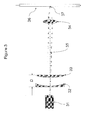
- Figure 2 shows a schematic representation of the illumination optics shown in figure 1 , wherein lens 12 has been displaced by a distance d from the optical path in a plane perpendicular to the optical path.
- the path of an arbitrary light ray 26 through the beam illumination optics is shown.
- the optical effect of displacing lens 12 a distance d in a plane perpendicular to the optical path is to move the focal spot to new focal spot 17, displaced from focal spot 16 by a distance ⁇ .
- lens 12 The optical effect of lens 12 on the illumination optics, relative to illumination optics having only focusing lens 13, is two-fold.
- the beam-adjusting lens allows for a lateral displacement of the focal spot of the illumination optics that is proportional to the displacement of the beam-adjusting lens in a plane perpendicular to the optical axis.
- lens 12 has a focal length much longer than the focal length of lens 13 and the distance between the lenses; more particularly,
- the displacement of the focal point is approximately ⁇ ⁇ d ⁇ f 13 f 12 - Z .
- >> f 13 the displacement of the focal spot is greatly reduced relative to the displacement of the beam-adjusting lens 12. This reduced sensitivity of the focal spot adjustment to movement of the beam-adjusting lens enables obtaining a high degree of precision over the adjustment of the focal spot using less expensive lens adjusting mechanisms with less precise motion control.
- the focal length of lens 12 is such that
- the preferred focal length of lens 12 and distance z are selected based on the particular application, including the desired focal point adjustment sensitivity and the resolution of the lens adjusting mechanism.
- FIG. 1 and 2 depict the focusing optics as a single focusing lens (lens 13), more complex optics may be used, such as optics having multiple lens elements and, optionally, beam shaping optics, such as described in U.S. Patent No. 4,498,766 and U.S. Patent Application Publication No. 2006-0256335 , both incorporated herein by reference.
- Figure 3 shows a schematic representation of an embodiment of the illumination optics of the present invention in which the beam-adjusting optics consist of plano-concave lens 32 and plano-convex lens 33, separated by a distance D .
- Light source 31 emits a beam having optical path 35, which is focused to a focal spot 37 on the flow stream 36 by focusing lens 34.
- One of lenses 32 and 33 is mounted such that the lens can be moved in a plane perpendicular to the optical path, such as by using a mechanical positioning system (not shown).
- plano-concave lens 32 and plano-convex lens 33 are positioned such that the optical path is centered in each of the lenses, i.e., the optical axes of the lenses coincides with the optical path.
- the focal spot 37 of the illumination optics is not displaced by the beam-adjusting optics from the optical path 35.
- Figure 4 shows a schematic representation of the beam illumination optics shown in figure 3 , wherein lens 33 has been displaced by a distance d from the optical path in a plane perpendicular to the optical path. The path of an arbitrary light ray 46 through the beam illumination optics is shown.
- lens pair 32 and 33 The optical effect of lens pair 32 and 33 on the illumination optics, relative to illumination optics having only focusing lens 34, is two-fold.
- the equivalent focal length, f eq f 32 ⁇ f 33 f 32 + f 33 - D , wherein f 32 and f 33 are the focal lengths of lens 32 and lens 33, respectively, and D is the distance between lens 32 and lens 33.
- f eq ⁇ - f 32 2 D the equivalent focal length of the lens pair is much longer than the focal length of the individual lenses.
- equation (8) shows that, in this embodiment, the lens pair will have a negligible effect on the effective focal length of the illumination optics.
- the displacement of the focal spot induced by a displacement of one of the lenses of the lens pair 32 and 33 can be obtained from an analysis of the optical property of the lens pair on the path of light ray 46 using the well-known ray tracing technique of ray transfer matrix analysis (see, for example, Warren J. Smith, 1996, Modem Optical Engineering: The Design of Optical Systems, 2nd Ed. (McGraw-Hill, Inc., New York, NY ), incorporated herein by reference).
- ray transfer matrix analysis also known as ABCD matrix analysis
- an optical system e.g., one or more lenses
- a vector representing the light ray leaving the system is determine by multiplying the ray transfer matrix with a vector representing the light ray entering the system.
- the technique uses the paraxial approximation of ray optics in which a ray is assumed to be at a small angle ( ⁇ ) to the optical axis of the system and remain at a small distance (x) from the optical axis of the system.
- an arbitrary paraxial light ray is specified by the vector x ⁇ , wherein x is the distance of the ray from the optical axis, and ⁇ is the angle between the ray and the optical axis.
- x ⁇ ⁇ 1 0 - 1 / f 1 ⁇ x ⁇ + 0 - d / f .
- x ⁇ ⁇ 1 0 - 1 / f 33 1 ⁇ 1 D 0 1 ⁇ 1 0 - 1 / f 32 1 ⁇ x ⁇ + 0 - d / f 33 .
- any ray that is nearly parallel to the optical axis i.e., for which ⁇ ⁇ 0
- the displacement of the focal spot is greatly reduced relative to the displacement of the beam-adjusting lens 33.
- This reduced sensitivity of the focal spot adjustment to movement of the beam-adjusting lens enables obtaining a high degree of precision over the adjustment of the focal spot using less expensive lens adjusting mechanisms with less precise motion control.
Landscapes
- Chemical & Material Sciences (AREA)
- Physics & Mathematics (AREA)
- General Physics & Mathematics (AREA)
- Biochemistry (AREA)
- Dispersion Chemistry (AREA)
- Health & Medical Sciences (AREA)
- Life Sciences & Earth Sciences (AREA)
- Analytical Chemistry (AREA)
- General Health & Medical Sciences (AREA)
- Immunology (AREA)
- Pathology (AREA)
- Optics & Photonics (AREA)
- Investigating, Analyzing Materials By Fluorescence Or Luminescence (AREA)
- Microscoopes, Condenser (AREA)
- Mounting And Adjusting Of Optical Elements (AREA)
- Moving Of The Head For Recording And Reproducing By Optical Means (AREA)
Applications Claiming Priority (1)
| Application Number | Priority Date | Filing Date | Title |
|---|---|---|---|
| US99375807P | 2007-09-14 | 2007-09-14 |
Publications (2)
| Publication Number | Publication Date |
|---|---|
| EP2058688A2 true EP2058688A2 (fr) | 2009-05-13 |
| EP2058688A3 EP2058688A3 (fr) | 2013-05-22 |
Family
ID=40454181
Family Applications (1)
| Application Number | Title | Priority Date | Filing Date |
|---|---|---|---|
| EP08164246.4A Ceased EP2058688A3 (fr) | 2007-09-14 | 2008-09-12 | Optique de réglage de faisceau |
Country Status (3)
| Country | Link |
|---|---|
| US (1) | US7787197B2 (fr) |
| EP (1) | EP2058688A3 (fr) |
| JP (1) | JP5437613B2 (fr) |
Families Citing this family (11)
| Publication number | Priority date | Publication date | Assignee | Title |
|---|---|---|---|---|
| US8223445B2 (en) * | 2009-09-21 | 2012-07-17 | Cytopeia | Lens positioning apparatus |
| US9746412B2 (en) | 2012-05-30 | 2017-08-29 | Iris International, Inc. | Flow cytometer |
| US10338354B2 (en) | 2016-07-18 | 2019-07-02 | Coherent, Inc. | Achromatic anastigmatic anamorphic objective |
| US10663700B2 (en) * | 2018-01-30 | 2020-05-26 | Coherent, Inc. | Achromatic astigmatic anamorphic objective |
| CA3211350A1 (fr) | 2018-03-30 | 2019-10-03 | Idexx Laboratories, Inc. | Cytometre en flux, ensemble optique laser associe et procedes d'assemblage associes |
| US11169386B2 (en) * | 2019-04-24 | 2021-11-09 | Coherent, Inc. | Beam forming with focus location adjustment |
| US11329722B2 (en) | 2020-03-27 | 2022-05-10 | Relative Dynamics Incorporated | Optical terminals |
| CN115917292B (zh) | 2020-06-17 | 2023-08-25 | Idexx实验室公司 | 流式细胞仪及其激光光学组件 |
| US20220120658A1 (en) * | 2020-10-20 | 2022-04-21 | Becton, Dickinson And Company | Flow cytometers including tilted beam shaping optical components, and methods of using the same |
| CN116429695B (zh) * | 2023-05-09 | 2024-06-21 | 无锡启烨生物科技有限公司 | 一种具有可变束调光光源的微流生化分析仪 |
| CN119395711B (zh) * | 2024-12-31 | 2025-05-06 | 上海市眼病防治中心 | 一种基于相控阵红外装置的读写坐姿监控桌面设备 |
Citations (3)
| Publication number | Priority date | Publication date | Assignee | Title |
|---|---|---|---|---|
| US4498766A (en) | 1982-03-25 | 1985-02-12 | Becton, Dickinson And Company | Light beam focal spot elongation in flow cytometry devices |
| US4989977A (en) | 1985-07-29 | 1991-02-05 | Becton, Dickinson And Company | Flow cytometry apparatus with improved light beam adjustment |
| US20060256335A1 (en) | 2005-05-13 | 2006-11-16 | Becton, Dickinson And Company | Optical beam-shaper |
Family Cites Families (14)
| Publication number | Priority date | Publication date | Assignee | Title |
|---|---|---|---|---|
| US4385834A (en) * | 1980-07-28 | 1983-05-31 | Westinghouse Electric Corp. | Laser beam boresight system |
| US4447119A (en) * | 1981-11-02 | 1984-05-08 | Gould, Inc. | Apparatus for maintaining an optical fiber and a focusing means |
| US5077622A (en) * | 1990-05-31 | 1991-12-31 | The United States Of America As Represented By The Administrator Of The National Aeronautics And Space Administration | Apparatus for precision focussing and positioning of a beam waist on a target |
| AU3235095A (en) * | 1994-08-01 | 1996-03-04 | Abbott Laboratories | Pseudo telecentric optical design for flow cytometric blood cell analyzer |
| US7218448B1 (en) * | 1997-03-17 | 2007-05-15 | The Regents Of The University Of Colorado | Extended depth of field optical systems |
| US5813987A (en) * | 1995-08-01 | 1998-09-29 | Medispectra, Inc. | Spectral volume microprobe for analysis of materials |
| JP2869423B2 (ja) * | 1995-12-28 | 1999-03-10 | シスメックス株式会社 | 流体中の粒子分析装置 |
| US7880117B2 (en) * | 2002-12-24 | 2011-02-01 | Panasonic Corporation | Method and apparatus of drilling high density submicron cavities using parallel laser beams |
| DK2959774T3 (da) * | 2003-03-28 | 2019-05-13 | Inguran Llc | Fremgangsmåde til kryokonservering af sædceller |
| US7468789B2 (en) | 2004-02-05 | 2008-12-23 | Advanced Analytical Technologies, Inc. | Flow cytometer for rapid bacteria detection |
| JP2006107584A (ja) * | 2004-10-01 | 2006-04-20 | Konica Minolta Opto Inc | 光学素子及び光スポット位置調整方法 |
| JP2007281345A (ja) * | 2006-04-11 | 2007-10-25 | Sony Corp | スタンドの回動機構及び電子機器 |
| US8027096B2 (en) * | 2006-12-15 | 2011-09-27 | Hand Held Products, Inc. | Focus module and components with actuator polymer control |
| TW200831977A (en) * | 2007-01-23 | 2008-08-01 | Asia Optical Co Inc | Miniature lens |
-
2008
- 2008-09-04 US US12/231,720 patent/US7787197B2/en active Active
- 2008-09-10 JP JP2008232361A patent/JP5437613B2/ja active Active
- 2008-09-12 EP EP08164246.4A patent/EP2058688A3/fr not_active Ceased
Patent Citations (3)
| Publication number | Priority date | Publication date | Assignee | Title |
|---|---|---|---|---|
| US4498766A (en) | 1982-03-25 | 1985-02-12 | Becton, Dickinson And Company | Light beam focal spot elongation in flow cytometry devices |
| US4989977A (en) | 1985-07-29 | 1991-02-05 | Becton, Dickinson And Company | Flow cytometry apparatus with improved light beam adjustment |
| US20060256335A1 (en) | 2005-05-13 | 2006-11-16 | Becton, Dickinson And Company | Optical beam-shaper |
Non-Patent Citations (3)
| Title |
|---|
| SHAPIRO: "Practical Flow Cytometry", 2003, JOHN WILEY AND SONS |
| SHAPIRO: "Practical Flow Cytometry", 2003, JOLM WILEY AND SONS, INC. |
| WARREN J. SMITH: "Modem Optical Engineering: The Design of Optical Systems", 1996, MCGRAW-HILL, INC. |
Also Published As
| Publication number | Publication date |
|---|---|
| EP2058688A3 (fr) | 2013-05-22 |
| US7787197B2 (en) | 2010-08-31 |
| JP2009156861A (ja) | 2009-07-16 |
| JP5437613B2 (ja) | 2014-03-12 |
| US20090073579A1 (en) | 2009-03-19 |
Similar Documents
| Publication | Publication Date | Title |
|---|---|---|
| US7787197B2 (en) | Beam-adjusting optics | |
| US8223445B2 (en) | Lens positioning apparatus | |
| US4545677A (en) | Prismatic beam expander for light beam shaping in a flow cytometry apparatus | |
| US7492522B2 (en) | Optical detector for a particle sorting system | |
| CN106019608B (zh) | 一种类高斯平顶光束激光系统 | |
| US5446532A (en) | Measuring apparatus with optically conjugate radiation fulcrum and irradiated area | |
| JPH0544622B2 (fr) | ||
| US11333605B2 (en) | Sample measurement device and sample measurement method | |
| US11204310B2 (en) | Optical flow cytometer for epi fluorescence measurement | |
| CN113008768B (zh) | 一种用于流式细胞仪的反射式荧光收集装置 | |
| US12209947B2 (en) | Optical system and flow cytometer | |
| US7369220B2 (en) | Measuring apparatus | |
| US20250130158A1 (en) | Optical system for sample processing instrument and sample processing instrument | |
| CN113811755B (zh) | 带焦点位置调整的光束形成 | |
| US12313522B2 (en) | Systems and methods for improved imaging and fluorescence in flow cytometry and other applications | |
| CN206178259U (zh) | 一种类高斯平顶光束激光系统 | |
| US20240133794A1 (en) | Optical particle analyser with illumination at an oblique angle onto a non-transparent microfluidic chip | |
| You | Diffractive Beam Shaper for Multiwavelength Lasers for Flow Cytometry | |
| CN119715328A (zh) | 一种高通量光学质谱仪及单分子小蛋白检测系统 | |
| CN116583737A (zh) | 用于改进流式细胞术和其他应用中的成像和荧光的系统和方法 |
Legal Events
| Date | Code | Title | Description |
|---|---|---|---|
| PUAI | Public reference made under article 153(3) epc to a published international application that has entered the european phase |
Free format text: ORIGINAL CODE: 0009012 |
|
| AK | Designated contracting states |
Kind code of ref document: A2 Designated state(s): AT BE BG CH CY CZ DE DK EE ES FI FR GB GR HR HU IE IS IT LI LT LU LV MC MT NL NO PL PT RO SE SI SK TR |
|
| AX | Request for extension of the european patent |
Extension state: AL BA MK RS |
|
| PUAL | Search report despatched |
Free format text: ORIGINAL CODE: 0009013 |
|
| AK | Designated contracting states |
Kind code of ref document: A3 Designated state(s): AT BE BG CH CY CZ DE DK EE ES FI FR GB GR HR HU IE IS IT LI LT LU LV MC MT NL NO PL PT RO SE SI SK TR |
|
| AX | Request for extension of the european patent |
Extension state: AL BA MK RS |
|
| RIC1 | Information provided on ipc code assigned before grant |
Ipc: G02B 7/08 20060101ALI20130415BHEP Ipc: G01N 15/14 20060101AFI20130415BHEP |
|
| 17P | Request for examination filed |
Effective date: 20131106 |
|
| AKX | Designation fees paid |
Designated state(s): AT BE BG CH CY CZ DE DK EE ES FI FR GB GR HR HU IE IS IT LI LT LU LV MC MT NL NO PL PT RO SE SI SK TR |
|
| 17Q | First examination report despatched |
Effective date: 20140424 |
|
| STAA | Information on the status of an ep patent application or granted ep patent |
Free format text: STATUS: THE APPLICATION HAS BEEN REFUSED |
|
| 18R | Application refused |
Effective date: 20150220 |