EP2058830B1 - Commutateur électromagnétique pour machine électrique - Google Patents
Commutateur électromagnétique pour machine électrique Download PDFInfo
- Publication number
- EP2058830B1 EP2058830B1 EP08105676.4A EP08105676A EP2058830B1 EP 2058830 B1 EP2058830 B1 EP 2058830B1 EP 08105676 A EP08105676 A EP 08105676A EP 2058830 B1 EP2058830 B1 EP 2058830B1
- Authority
- EP
- European Patent Office
- Prior art keywords
- protective cap
- pot
- pot bottom
- armature
- housing
- Prior art date
- Legal status (The legal status is an assumption and is not a legal conclusion. Google has not performed a legal analysis and makes no representation as to the accuracy of the status listed.)
- Not-in-force
Links
- 230000001681 protective effect Effects 0.000 claims description 70
- 239000007858 starting material Substances 0.000 claims description 25
- 238000005452 bending Methods 0.000 claims description 12
- 238000007789 sealing Methods 0.000 claims description 6
- 238000002485 combustion reaction Methods 0.000 claims description 5
- 230000007704 transition Effects 0.000 claims description 5
- 230000015572 biosynthetic process Effects 0.000 claims description 4
- 238000005096 rolling process Methods 0.000 claims description 3
- 230000003467 diminishing effect Effects 0.000 claims 1
- 230000001747 exhibiting effect Effects 0.000 claims 1
- 239000000463 material Substances 0.000 description 7
- 238000006073 displacement reaction Methods 0.000 description 6
- 239000011324 bead Substances 0.000 description 5
- 230000015556 catabolic process Effects 0.000 description 4
- 230000007423 decrease Effects 0.000 description 3
- 229920002379 silicone rubber Polymers 0.000 description 3
- 239000004945 silicone rubber Substances 0.000 description 3
- 230000000295 complement effect Effects 0.000 description 2
- 230000007797 corrosion Effects 0.000 description 2
- 238000005260 corrosion Methods 0.000 description 2
- 230000006378 damage Effects 0.000 description 2
- 230000000694 effects Effects 0.000 description 2
- 229920001971 elastomer Polymers 0.000 description 2
- 230000002093 peripheral effect Effects 0.000 description 2
- 230000000750 progressive effect Effects 0.000 description 2
- 230000001419 dependent effect Effects 0.000 description 1
- 238000011161 development Methods 0.000 description 1
- 230000018109 developmental process Effects 0.000 description 1
- 230000005284 excitation Effects 0.000 description 1
- 238000003780 insertion Methods 0.000 description 1
- 230000037431 insertion Effects 0.000 description 1
- 239000007788 liquid Substances 0.000 description 1
- 238000000034 method Methods 0.000 description 1
- 230000002028 premature Effects 0.000 description 1
- 230000008719 thickening Effects 0.000 description 1
Images



Classifications
-
- H—ELECTRICITY
- H01—ELECTRIC ELEMENTS
- H01H—ELECTRIC SWITCHES; RELAYS; SELECTORS; EMERGENCY PROTECTIVE DEVICES
- H01H51/00—Electromagnetic relays
- H01H51/02—Non-polarised relays
- H01H51/04—Non-polarised relays with single armature; with single set of ganged armatures
- H01H51/06—Armature is movable between two limit positions of rest and is moved in one direction due to energisation of an electromagnet and after the electromagnet is de-energised is returned by energy stored during the movement in the first direction, e.g. by using a spring, by using a permanent magnet, by gravity
- H01H51/065—Relays having a pair of normally open contacts rigidly fixed to a magnetic core movable along the axis of a solenoid, e.g. relays for starting automobiles
-
- H—ELECTRICITY
- H01—ELECTRIC ELEMENTS
- H01H—ELECTRIC SWITCHES; RELAYS; SELECTORS; EMERGENCY PROTECTIVE DEVICES
- H01H50/00—Details of electromagnetic relays
- H01H50/02—Bases; Casings; Covers
- H01H50/023—Details concerning sealing, e.g. sealing casing with resin
-
- H—ELECTRICITY
- H01—ELECTRIC ELEMENTS
- H01H—ELECTRIC SWITCHES; RELAYS; SELECTORS; EMERGENCY PROTECTIVE DEVICES
- H01H9/00—Details of switching devices, not covered by groups H01H1/00 - H01H7/00
- H01H9/02—Bases, casings, or covers
- H01H9/04—Dustproof, splashproof, drip-proof, waterproof, or flameproof casings
- H01H2009/048—Dustproof, splashproof, drip-proof, waterproof, or flameproof casings using a sealing boot, e.g. the casing having separate elastic body surrounding the operating member and hermetically closing the opening for it
Definitions
- the invention relates to an electromagnetic switch, in particular a starter relay, for an electric starter motor for controlling to engage a starter pinion when starting an internal combustion engine, with a housing, an electromagnetically controllable armature of a control lever and a flexible cap, the seals a transition from the housing to the anchor, wherein the protective cap is pot-shaped with a pot opening and a pot bottom, the pot bottom has a circular opening with a thickened ring for positive connection with the anchor and the pot opening formed reinforced on the peripheral edge for positive connection with the housing is.
- the pot bottom seen in cross-section, has a desired bending range.
- the invention further relates to a fastening method of a protective cap for an electromagnetic switch, wherein the protective cap sealingly connects a housing and an armature.
- a protective cap which has a flange-shaped bead at its pot opening.
- the protective cap is attached to the housing of an electromagnetic switch.
- a ring which is screwed from the outside onto the flange of the protective cap, creates a form-liquid connection of the protective cap to the housing of the electromagnetic switch.
- the protective cap is also referred to as rubber bellows due to its elastic rubber material.
- the DE 102 60 843 A1 describes a starter relay for engaging a starter pinion in a ring gear of an internal combustion engine to switch a starter motor for starting.
- An elastic cup-shaped protective cap closes a free end of a controllable anchor rod with the housing of the starter relay.
- the cup-shaped protective cap is formed bellows-shaped in a mounting portion in the region of the housing. The protective cap is pushed in the retracted state of the anchor rod. In the extended state of the anchor rod, the cap has a cone-shaped wall to the anchor rod.
- the JP 2005-174590 A1 describes an electromagnetic switch for starter motors with a cup-shaped protective cap.
- the DE 28 43 593 A1 describes an AC magnet with an actuator and an excitation coil, wherein the actuator is secured to the exciter coil by means of a bellows for protection against dirt and moisture.
- the bellows is a bellows and has at Faltenbalgende or at the opening a circular bead which is form-fitting on the housing can be fitted on.
- a circular opening in the pot bottom of the protective cap engages in a press fit the anchor rod of the electromagnetic switch.
- the protective cap folds around in a desired bending area.
- the protective cap during insertion of the anchor rod into the housing of the switch possibly corners, in plan view, for example, in a triangle form. This leads to increased material fatigue and thus to a faster destruction of the cap.
- Protective cap bulges may come into contact with the contour of the housing and the anchor rod and thus cause increased wear and life of the protective cap.
- the formation of strongly folded corners can also be represented in a force-displacement curve of a cup-shaped protective cap whose force increases exponentially to a maximum. At the maximum, the protective cap beats through, so to speak, assuming a lower energy level, starting from the path at which the corners form and a magnetically generated pull-in force of the armature counteracting opposing force of the protective cap is reduced.
- the pot base of the protective cap has at least two predetermined bending areas in the radial direction when viewed in cross-section.
- the first desired bending region has a large diameter, substantially the diameter corresponding to the outer diameter of the top shape of the protective cap and at least a second desired bending region has a smaller diameter than the cup shape of the protective cap and coaxial with the cup shape of the protective cap. Due to the two desired bending areas, the formation of corners when retracting the pot bottom into the cup-shaped protective cap is reliably avoided. A circular fold creates in contrast to trained corners no additional wear, so that the lifetime is advantageously long.
- the bottom of the pot has at least two punctures with increasing path of movement of the pot bottom in the interior of the pot, wherein in a breakdown of a generated by the flexible cap counterforce with respect to the progressive path of movement decreases inwardly for a short time.
- the large breakdown which has proved to be disadvantageous is in the rear region of the path of movement of the pot bottom replaced in the direction of pot opening by a plurality of small punctures in the initial and central region of the movement path of the pot bottom according to the invention.
- These several small punctures lead to a defined circular folding from the inside to the outside and do not lead to a negative Aufhornung, such as the formation of corners during the so-called unrolling of the cap.
- the protective cap is preferably made of a silicone rubber material for flexible circular folding.
- the bottom of the pot has three punctures, wherein seen in cross section in the radial direction two rounded steps are formed in the bottom of the pot, which are connected to a curved or conical connection region.
- a protective cap has the advantage that the protective cap space and material is optimizing.
- the circular opening in the bottom of the pot is formed with a circular, final and sealing ring, as seen in cross-section.
- the ring is freely pivotable in an annular groove on the armature in the radial direction by an angular range. This has the advantage of a long life of the cap with it.
- the Fig. 1 shows in cross-section a starting device for starting an internal combustion engine of a vehicle with an electromagnetic switch, which is referred to as a starter relay 1 hereinafter.
- the starter relay 1 comprises a housing 2 with an electromagnetically controllable armature 3.
- the electromagnetic armature 3 is by means of at least one in the Fig. 2 drawn spring 8 pushed out of the housing 2 on one side.
- the starter relay 1 is energized, the armature 3 is pulled into the housing 2.
- armature 3 is a control lever 4, which brings a starter pinion of an electromagnetic starter motor 40 into engagement, so that an internal combustion engine is started upon actuation of the starter motor 40.
- the transition from the housing 2 to the armature 3 must be sealed to prevent the ingress of moisture into the starter relay 1, in particular in Fig. 2 shown contact space 9 from the armature 3, to prevent. Corrosion in the contact space 9 can lead to contact difficulties and corrosion at the armature 3 and thus to a stiff starter relay 1 or to functional failure.
- a flexible cap 5 made of a silicone rubber material intended.
- the protective cap 5 is cup-shaped.
- a pot bottom 6 is sealingly connected to the armature 3 and on the other side a pot opening 7 is sealed by the protective cap 5 with the housing 2.
- the Fig. 2 shows an enlarged section in a sectional view of Fig. 1 the transition between the housing 2 and the armature 3.
- the armature 3 is pushed out of the magnetic contact space 9 by means of the spring 8.
- This strained and not energized state shows the Fig. 2 ,
- the housing 2 has to guide the armature 3, a cylindrical flange 10 which has a circumferential housing groove 11 on the outside.
- the housing groove 11 is to highlight the inner wall in the region of the pot opening 7 of the in the Fig. 3 shown protective cap 5 formed complementary.
- a driver 12 with a Einspurfeder 13 is guided in the armature 3.
- the driver 12 acts directly on the in Fig. 1 shown control lever 4 a.
- a closure cap 14 closes the Einspurfeder 13 in the armature 3 from.
- the closure cap 14 has a circumferential annular groove 15.
- the annular groove 15 takes a thickened ring 17 of a circular opening 16 in the bottom of the pot 6 of the cap 5, as in the Fig. 3 shown on.
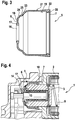
- the Fig. 3 shows in cross section the protective cap 5 according to the invention according to the preferred embodiment.
- the protective cap 5 is substantially pot-shaped.
- the protective cap 5 has the circular opening 16 in the pot bottom 6.
- the circular opening 16 is formed in the bottom of the pot 6 with a circular in cross-section, final and sealing the armature 3 ring 17.
- the ring 17 is placed and fitted during assembly of the starter relay 1 in the annular groove 15 of the cap 14.
- the pot bottom 6 further has a compensation opening 18 to allow gas volume to flow out of or into the protective cap 5 when the pot bottom 6 is moved in the direction of the pot opening 7 or away from the pot opening 7.
- the protective cap 5 has for the positive connection with the housing 2 on its inner wall 19 an annular bead 20, seen in cross-section in the form of a semicircle, the pot opening 7 is formed thickening.
- the outer wall 21 is seen to the pot opening 7 in cross-section conical enlarged with then cylindrical, constant strength - seen in cross section - formed in a rectangular shape.
- the outer wall 21 is thus formed opposite to the bead 20 as a cylindrical wall 22.
- the pot bottom 6 seen in cross section in the radial direction in contrast to the prior art not only a desired bending range, but at least two desired bending areas with a first and a second stage 23, 24.
- the steps 23, 24 are rounded in the protective cap 5 produced from a silicone rubber material and connected by means of a connecting region 25 rounded off in a manner complementary to the first and second steps 23, 24. Due to the two stages 23, 24 and the connection region 25 in the bottom of the pot 6 results in a collection of the bottom of the pot 6 a defined circular folding of the bottom of the pot 6 at the same time minimal space.
- the Fig. 4 shows the protective cap 5 according to the invention in the installed state in a cross-sectional view of the in Fig. 2 shown detail.
- the ring 17 of the pot bottom 6 is located in the annular groove 15 of the cap 14.
- the pot opening 7 is positively connected to the cylindrical flange 10 of the housing 2.
- Fig. 4 shows the starter relay 1 with an armature 3 in the de-energized state.
- the Fig. 5 shows a radial cross-section of a protective cap 5 according to the invention with a relaxed anchor 3.
- the protective cap 5 has according to this embodiment, the positive connection of the pot opening 7 with the cylindrical flange 10 of the housing 2.
- the bottom of the pot 6 has only one step 23, which has a defined round bend according to the Fig. 6 generated when the armature 3 with the cap 14 in the in the Fig. 4 shown contact space 9 retracts.
- the Fig. 6 shows the protective cap 5 in an at least partially retracted state of the armature 3.
- the seen in cross section circular ring 17 can pivot in the annular groove 15 of the cap 14 in an angular range of at least 30 to 60 °.
- the cylindrical wall 22 of the outer wall 21 terminates flush with the cylindrical flange 10 of the housing 2.
- a cylindrical inner wall of a housing cover 26 is formed directly adjacent to the cylindrical wall 22, so that the positive connection of the pot opening 7 with the cylindrical flange 10 of the housing 2 securely seals and can not slip out.
- the Fig. 6 shows the protective cap 5 with a circular fold in the area of the first stage 23.
- the cap 5 no longer evenly round, but forms with strongly folded corners.
- the bulges formed as corners come into contact with the contours of the housing cover 26 or of the drive bearing, ie with the control lever 4 designed as a fork. This can lead to a lifetime reduction due to increased wear.
- the protective cap 5 as in the Fig. 7 shown in perspective view, in the region of the pot bottom 6, two target bending areas with a first stage 23 and second stage 24.
- the circular opening 16 is minimally driven.
- the wall of the protective cap 5 initially extends radially outward to a diameter of the first stage 24 which is smaller than the end diameter of the protective cap 5.
- the wall bends obliquely to the radius in the axial direction to then approach the final outer diameter in a continuous transition in the first stage 23.
- the wall thickness of the protective cap 5 can steadily increase in a particular embodiment of the first stage 23 to the pot opening 7.
- the Fig. 8 shows the protective cap 5 according to the invention according to the Fig. 7 in a perspective view in the retracted state of the bottom of the pot. 6
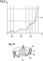
- the Fig. 9 shows a force-displacement curve 27 of the protective cap 5 according to the second preferred embodiment.
- the force-displacement curve 27 shows that a counterforce F of the protective cap 5 increases exponentially with increasing movement path X of the pot base 6 in the direction of the pot opening 7.
- the protective cap 5 has a rolling behavior with a plurality of smaller punches 28, 29 or 30. After a breakdown, the counterforce F generated by the flexible protective cap 5 briefly decreases with respect to the progressive movement path X.
- the protective cap 5 according to the invention folds round. Folded corners, for example in the triangle, which lead to material fatigue and premature destruction of the protective cap, are avoided according to the force-displacement curve 27.
- the small punctures 28, 29, 30 lead to a circular folding and not to a square deformation during the rolling of the pot bottom. 6
- the Fig. 10 shows a cross-sectional view of the in the Fig. 8 in perspective cap shown 5.
- the circular opening 16 of the pot bottom is retracted maximum inward.
- the first stage 23 is folded around the entire circumference, the second stage 24 is curved inward or straightened and in the connection region 25, in which the wall of the pot base 6, viewed in cross-section, is bent at an angle to the pot opening 7 and no longer from the pot opening 7.
Landscapes
- Physics & Mathematics (AREA)
- Electromagnetism (AREA)
- Connection Of Motors, Electrical Generators, Mechanical Devices, And The Like (AREA)
- Motor Or Generator Frames (AREA)
Claims (3)
- Commutateur électromagnétique, notamment le relai de démarreur (1), pour un moteur de démarreur électrique à commander en vue d'amener en prise un pignon de démarreur lors du lancement d'un moteur à combustion interne, comprenant un boîtier (2), un induit (3) pouvant être commandé de manière électromagnétique se trouvant dans celui-ci et destiné à commander un levier de commande (4) et comprenant un capuchon de protection (5) flexible qui rend étanche une transition du boîtier (2) à l'induit (3), le capuchon de protection (5) étant configuré en forme de pot avec un fond de pot (6) et une ouverture de pot (7), le fond de pot (6) possédant une ouverture (16) de forme circulaire avec un anneau (17) épaissi destiné à l'assemblage par complémentarité de formes avec l'induit (3) et l'ouverture de pot (7) étant réalisée renforcée au niveau du bord périphérique en vue de l'assemblage par complémentarité de formes avec le boîtier (2), le fond de pot (6), vu en coupe transversale, possédant une zone de flexion voulue, caractérisé en ce que le fond de pot (6) du capuchon de protection (5), vu en coupe transversale, possède au moins deux zones de flexion voulue dans le sens radial, le fond de pot (6) du capuchon de protection (5), lors de l'entrée de l'induit (3), présentant un comportement de déroulement avec pliage rond comportant au moins deux percements (28, 29, 30), une force opposée (F) concernant la course de déplacement en cours de propagation et générée par le capuchon de protection (5) flexible retournant pendant un court instant vers l'intérieur à chaque percement.
- Commutateur électromagnétique selon la revendication 1, caractérisé en ce que le fond de pot (6) possède trois percements (28, 29, 30), deux paliers arrondis (23, 24) étant formés dans le fond de pot (6) dans le sens radial, vu en coupe transversale, lesquels sont reliés à une zone de liaison (25) bombée ou conique.
- Commutateur électromagnétique selon l'une des revendications 1 ou 2, caractérisé en ce que l'ouverture (16) de forme circulaire dans le fond de pot (6) est configurée avec une bague (17) qui, vue en coupe transversale, est de forme circulaire, réalise la fermeture et réalise l'étanchéité.
Applications Claiming Priority (1)
| Application Number | Priority Date | Filing Date | Title |
|---|---|---|---|
| DE102007053417A DE102007053417A1 (de) | 2007-11-09 | 2007-11-09 | Elektromagnetischer Schalter für E-Maschine |
Publications (3)
| Publication Number | Publication Date |
|---|---|
| EP2058830A2 EP2058830A2 (fr) | 2009-05-13 |
| EP2058830A3 EP2058830A3 (fr) | 2011-05-18 |
| EP2058830B1 true EP2058830B1 (fr) | 2016-12-21 |
Family
ID=40340737
Family Applications (1)
| Application Number | Title | Priority Date | Filing Date |
|---|---|---|---|
| EP08105676.4A Not-in-force EP2058830B1 (fr) | 2007-11-09 | 2008-10-28 | Commutateur électromagnétique pour machine électrique |
Country Status (4)
| Country | Link |
|---|---|
| US (1) | US7973624B2 (fr) |
| EP (1) | EP2058830B1 (fr) |
| JP (1) | JP5404005B2 (fr) |
| DE (1) | DE102007053417A1 (fr) |
Families Citing this family (5)
| Publication number | Priority date | Publication date | Assignee | Title |
|---|---|---|---|---|
| DE102010003823B4 (de) | 2010-04-09 | 2019-03-28 | Seg Automotive Germany Gmbh | Abdeckring für Startvorrichtung |
| DE102014102362A1 (de) * | 2014-02-24 | 2015-08-27 | Norma Germany Gmbh | Verbinder für eine Fluidleitung |
| CN105679608B (zh) * | 2014-11-17 | 2020-03-13 | 索恩格汽车部件德国有限公司 | 电磁开关及车辆起动机 |
| FR3054368B1 (fr) * | 2016-07-21 | 2020-12-25 | Valeo Equip Electr Moteur | Contacteur de demarreur comprenant un dispositif de protection contre la poussiere, et demarreur equipe d'un tel contacteur |
| FR3066312B1 (fr) * | 2017-05-12 | 2019-06-28 | Valeo Equipements Electriques Moteur | Contacteur de demarreur comprenant un dispositif d'etancheite, et demarreur comprenant un tel contacteur |
Family Cites Families (16)
| Publication number | Priority date | Publication date | Assignee | Title |
|---|---|---|---|---|
| DE2843593A1 (de) * | 1978-10-06 | 1980-04-17 | Neue Hahn Magnet Gmbh & Co Kg | Wechselstrommagnet |
| JPS61256706A (ja) * | 1985-05-10 | 1986-11-14 | Hitachi Ltd | ソレノイド防塵カバ− |
| EP0218880B1 (fr) * | 1985-09-09 | 1990-06-06 | Nippondenso Co., Ltd. | Dispositif interrupteur pour démarreur de moteur à combustion interne |
| DE3632469A1 (de) * | 1986-09-24 | 1988-03-31 | Bosch Gmbh Robert | Elektromagnetischer schalter, insbesondere fuer andrehvorrichtungen von brennkraftmaschinen |
| JPS63280851A (ja) * | 1987-05-14 | 1988-11-17 | Nippon Denso Co Ltd | スタ−タ用マグネットスイッチ |
| NL8801588A (nl) * | 1988-06-22 | 1990-01-16 | Philips Nv | Werkwijze en inrichting voor het volumeselectief bepalen van een nmr-spectrum door middel van selectieve polarisatieoverdracht-pulssequenties. |
| JPH0218828A (ja) * | 1988-07-06 | 1990-01-23 | Mitsubishi Electric Corp | 電磁吸引装置 |
| JPH02301926A (ja) * | 1989-05-17 | 1990-12-14 | Mitsubishi Electric Corp | 電磁吸引装置 |
| DE4242930C2 (de) * | 1992-12-18 | 1998-07-09 | Bosch Gmbh Robert | Einrückrelais für Andrehvorrichtungen |
| DE4432297C2 (de) * | 1994-09-10 | 2002-06-27 | Bosch Gmbh Robert | Einrückrelais für Andrehvorrichtung von Brennkraftmaschinen |
| DE19818934C2 (de) * | 1998-04-28 | 2000-07-27 | Karl Kapfer | Schaltkasten mit in seiner Frontplatte eingebautem hülsen- oder stabförmigem Einbauteil |
| DE10260843B4 (de) | 2002-12-23 | 2020-10-29 | Seg Automotive Germany Gmbh | Relais, insbesondere Starterrelais für Brennkraftmaschinen |
| JP4241300B2 (ja) * | 2003-09-29 | 2009-03-18 | 株式会社デンソー | スタータ用電磁スイッチ |
| JP2005117459A (ja) | 2003-10-09 | 2005-04-28 | Nec Electronics Corp | 入力回路 |
| JP2005174590A (ja) | 2003-12-08 | 2005-06-30 | Denso Corp | スタータ用電磁スイッチ |
| JP4631845B2 (ja) * | 2006-12-06 | 2011-02-16 | 株式会社デンソー | スタータ用電磁スイッチ |
-
2007
- 2007-11-09 DE DE102007053417A patent/DE102007053417A1/de not_active Withdrawn
-
2008
- 2008-10-28 EP EP08105676.4A patent/EP2058830B1/fr not_active Not-in-force
- 2008-11-07 US US12/267,144 patent/US7973624B2/en not_active Expired - Fee Related
- 2008-11-10 JP JP2008288163A patent/JP5404005B2/ja not_active Expired - Fee Related
Non-Patent Citations (1)
| Title |
|---|
| None * |
Also Published As
| Publication number | Publication date |
|---|---|
| EP2058830A3 (fr) | 2011-05-18 |
| JP5404005B2 (ja) | 2014-01-29 |
| US7973624B2 (en) | 2011-07-05 |
| JP2009123698A (ja) | 2009-06-04 |
| US20090128266A1 (en) | 2009-05-21 |
| DE102007053417A1 (de) | 2009-05-14 |
| EP2058830A2 (fr) | 2009-05-13 |
Similar Documents
| Publication | Publication Date | Title |
|---|---|---|
| EP3215771B1 (fr) | Soupape proportionnelle, ensemble compresseur de climatisation et procédé de fonctionnement | |
| EP2136088B1 (fr) | Elément de liaison doté d'une vis et d'une douille agencée sur celle-ci de façon inamovible | |
| EP2137442B1 (fr) | Soupape électromagnétique et procédé de production | |
| EP2737224B1 (fr) | Carter de joint d'un joint à rotule et procédé de montage du carter de joint sur un élément de support | |
| DE102007052756A1 (de) | Kunststoffelement, Kolbenpumpe sowie Montageverfahren | |
| EP2261094A2 (fr) | Cartouche de vanne pour une électrovanne et électrovanne comprenant une telle cartouche | |
| DE112015003121T5 (de) | Dichtungsmechanismus für Antriebsgehäuse | |
| EP3121495B1 (fr) | Vanne de commande electromagnetique | |
| EP2058830A2 (fr) | Commutateur électromagnétique pour machine électrique | |
| EP2740874B1 (fr) | Procédé et dispositif de fermeture d'une ouverture dans un corps, notamment dans un actionneur de porte | |
| WO2003052307A1 (fr) | Soupape electromagnetique | |
| EP2449659A2 (fr) | Procédé de fabrication d'un moteur électrique | |
| WO2012076270A1 (fr) | Ensemble palier comportant un flasque et un palier fixe, notamment pour un papillon | |
| WO2010149526A2 (fr) | Palier de collecteur | |
| WO2014075908A1 (fr) | Arbre à cames | |
| DE102011085985A1 (de) | Elektromotorbaugruppe | |
| DE102016219676A1 (de) | Bauelement für die axiale Fixierung einer Flanschwelle in einem Hybridmodul | |
| EP2906372A1 (fr) | Procédé de fermeture d'une ouverture ménagée dans un élément, en particulier dans un actionneur de porte | |
| DE202013004443U1 (de) | Betätigungsvorrichtung für eine Klappe in oder an einem Automobil | |
| DE102015226755A1 (de) | Elektromotor für Stellantriebe in Kraftfahrzeugen und Getriebe-Antriebseinrichtung | |
| DE102019114175A1 (de) | Antrieb, insbesondere Spindelantrieb | |
| EP3146225B1 (fr) | Dispositif de ressort pour un embrayage à friction | |
| DE102017222985A1 (de) | Ventil, insbesondere Saugventil,in einer Hochdruckpumpe eines Kraftstoffeinspritzsystems | |
| DE102019135364A1 (de) | Stellvorrichtung | |
| DE102017222850A1 (de) | Elektrisch betätigtes Ventil, in einer Hochdruckpumpe eines Kraftstoffeinspritzsystems |
Legal Events
| Date | Code | Title | Description |
|---|---|---|---|
| PUAI | Public reference made under article 153(3) epc to a published international application that has entered the european phase |
Free format text: ORIGINAL CODE: 0009012 |
|
| AK | Designated contracting states |
Kind code of ref document: A2 Designated state(s): AT BE BG CH CY CZ DE DK EE ES FI FR GB GR HR HU IE IS IT LI LT LU LV MC MT NL NO PL PT RO SE SI SK TR |
|
| AX | Request for extension of the european patent |
Extension state: AL BA MK RS |
|
| PUAL | Search report despatched |
Free format text: ORIGINAL CODE: 0009013 |
|
| AK | Designated contracting states |
Kind code of ref document: A3 Designated state(s): AT BE BG CH CY CZ DE DK EE ES FI FR GB GR HR HU IE IS IT LI LT LU LV MC MT NL NO PL PT RO SE SI SK TR |
|
| AX | Request for extension of the european patent |
Extension state: AL BA MK RS |
|
| 17P | Request for examination filed |
Effective date: 20111118 |
|
| AKX | Designation fees paid |
Designated state(s): AT BE BG CH CY CZ DE DK EE ES FI FR GB GR HR HU IE IS IT LI LT LU LV MC MT NL NO PL PT RO SE SI SK TR |
|
| 17Q | First examination report despatched |
Effective date: 20121010 |
|
| GRAP | Despatch of communication of intention to grant a patent |
Free format text: ORIGINAL CODE: EPIDOSNIGR1 |
|
| INTG | Intention to grant announced |
Effective date: 20160927 |
|
| GRAS | Grant fee paid |
Free format text: ORIGINAL CODE: EPIDOSNIGR3 |
|
| GRAA | (expected) grant |
Free format text: ORIGINAL CODE: 0009210 |
|
| AK | Designated contracting states |
Kind code of ref document: B1 Designated state(s): AT BE BG CH CY CZ DE DK EE ES FI FR GB GR HR HU IE IS IT LI LT LU LV MC MT NL NO PL PT RO SE SI SK TR |
|
| REG | Reference to a national code |
Ref country code: GB Ref legal event code: FG4D Free format text: NOT ENGLISH |
|
| REG | Reference to a national code |
Ref country code: CH Ref legal event code: EP |
|
| REG | Reference to a national code |
Ref country code: IE Ref legal event code: FG4D Free format text: LANGUAGE OF EP DOCUMENT: GERMAN |
|
| REG | Reference to a national code |
Ref country code: AT Ref legal event code: REF Ref document number: 856139 Country of ref document: AT Kind code of ref document: T Effective date: 20170115 |
|
| REG | Reference to a national code |
Ref country code: DE Ref legal event code: R096 Ref document number: 502008014903 Country of ref document: DE |
|
| PG25 | Lapsed in a contracting state [announced via postgrant information from national office to epo] |
Ref country code: LV Free format text: LAPSE BECAUSE OF FAILURE TO SUBMIT A TRANSLATION OF THE DESCRIPTION OR TO PAY THE FEE WITHIN THE PRESCRIBED TIME-LIMIT Effective date: 20161221 |
|
| REG | Reference to a national code |
Ref country code: LT Ref legal event code: MG4D |
|
| REG | Reference to a national code |
Ref country code: NL Ref legal event code: MP Effective date: 20161221 |
|
| PG25 | Lapsed in a contracting state [announced via postgrant information from national office to epo] |
Ref country code: NO Free format text: LAPSE BECAUSE OF FAILURE TO SUBMIT A TRANSLATION OF THE DESCRIPTION OR TO PAY THE FEE WITHIN THE PRESCRIBED TIME-LIMIT Effective date: 20170321 Ref country code: GR Free format text: LAPSE BECAUSE OF FAILURE TO SUBMIT A TRANSLATION OF THE DESCRIPTION OR TO PAY THE FEE WITHIN THE PRESCRIBED TIME-LIMIT Effective date: 20170322 Ref country code: LT Free format text: LAPSE BECAUSE OF FAILURE TO SUBMIT A TRANSLATION OF THE DESCRIPTION OR TO PAY THE FEE WITHIN THE PRESCRIBED TIME-LIMIT Effective date: 20161221 Ref country code: SE Free format text: LAPSE BECAUSE OF FAILURE TO SUBMIT A TRANSLATION OF THE DESCRIPTION OR TO PAY THE FEE WITHIN THE PRESCRIBED TIME-LIMIT Effective date: 20161221 |
|
| PG25 | Lapsed in a contracting state [announced via postgrant information from national office to epo] |
Ref country code: HR Free format text: LAPSE BECAUSE OF FAILURE TO SUBMIT A TRANSLATION OF THE DESCRIPTION OR TO PAY THE FEE WITHIN THE PRESCRIBED TIME-LIMIT Effective date: 20161221 Ref country code: FI Free format text: LAPSE BECAUSE OF FAILURE TO SUBMIT A TRANSLATION OF THE DESCRIPTION OR TO PAY THE FEE WITHIN THE PRESCRIBED TIME-LIMIT Effective date: 20161221 |
|
| PG25 | Lapsed in a contracting state [announced via postgrant information from national office to epo] |
Ref country code: NL Free format text: LAPSE BECAUSE OF FAILURE TO SUBMIT A TRANSLATION OF THE DESCRIPTION OR TO PAY THE FEE WITHIN THE PRESCRIBED TIME-LIMIT Effective date: 20161221 |
|
| PG25 | Lapsed in a contracting state [announced via postgrant information from national office to epo] |
Ref country code: CZ Free format text: LAPSE BECAUSE OF FAILURE TO SUBMIT A TRANSLATION OF THE DESCRIPTION OR TO PAY THE FEE WITHIN THE PRESCRIBED TIME-LIMIT Effective date: 20161221 Ref country code: IS Free format text: LAPSE BECAUSE OF FAILURE TO SUBMIT A TRANSLATION OF THE DESCRIPTION OR TO PAY THE FEE WITHIN THE PRESCRIBED TIME-LIMIT Effective date: 20170421 Ref country code: SK Free format text: LAPSE BECAUSE OF FAILURE TO SUBMIT A TRANSLATION OF THE DESCRIPTION OR TO PAY THE FEE WITHIN THE PRESCRIBED TIME-LIMIT Effective date: 20161221 Ref country code: EE Free format text: LAPSE BECAUSE OF FAILURE TO SUBMIT A TRANSLATION OF THE DESCRIPTION OR TO PAY THE FEE WITHIN THE PRESCRIBED TIME-LIMIT Effective date: 20161221 Ref country code: RO Free format text: LAPSE BECAUSE OF FAILURE TO SUBMIT A TRANSLATION OF THE DESCRIPTION OR TO PAY THE FEE WITHIN THE PRESCRIBED TIME-LIMIT Effective date: 20161221 |
|
| PG25 | Lapsed in a contracting state [announced via postgrant information from national office to epo] |
Ref country code: ES Free format text: LAPSE BECAUSE OF FAILURE TO SUBMIT A TRANSLATION OF THE DESCRIPTION OR TO PAY THE FEE WITHIN THE PRESCRIBED TIME-LIMIT Effective date: 20161221 Ref country code: PT Free format text: LAPSE BECAUSE OF FAILURE TO SUBMIT A TRANSLATION OF THE DESCRIPTION OR TO PAY THE FEE WITHIN THE PRESCRIBED TIME-LIMIT Effective date: 20170421 Ref country code: BG Free format text: LAPSE BECAUSE OF FAILURE TO SUBMIT A TRANSLATION OF THE DESCRIPTION OR TO PAY THE FEE WITHIN THE PRESCRIBED TIME-LIMIT Effective date: 20170321 Ref country code: PL Free format text: LAPSE BECAUSE OF FAILURE TO SUBMIT A TRANSLATION OF THE DESCRIPTION OR TO PAY THE FEE WITHIN THE PRESCRIBED TIME-LIMIT Effective date: 20161221 Ref country code: IT Free format text: LAPSE BECAUSE OF FAILURE TO SUBMIT A TRANSLATION OF THE DESCRIPTION OR TO PAY THE FEE WITHIN THE PRESCRIBED TIME-LIMIT Effective date: 20161221 |
|
| REG | Reference to a national code |
Ref country code: DE Ref legal event code: R097 Ref document number: 502008014903 Country of ref document: DE |
|
| PLBE | No opposition filed within time limit |
Free format text: ORIGINAL CODE: 0009261 |
|
| STAA | Information on the status of an ep patent application or granted ep patent |
Free format text: STATUS: NO OPPOSITION FILED WITHIN TIME LIMIT |
|
| REG | Reference to a national code |
Ref country code: DE Ref legal event code: R081 Ref document number: 502008014903 Country of ref document: DE Owner name: SEG AUTOMOTIVE GERMANY GMBH, DE Free format text: FORMER OWNER: ROBERT BOSCH GMBH, 70469 STUTTGART, DE |
|
| 26N | No opposition filed |
Effective date: 20170922 |
|
| PG25 | Lapsed in a contracting state [announced via postgrant information from national office to epo] |
Ref country code: DK Free format text: LAPSE BECAUSE OF FAILURE TO SUBMIT A TRANSLATION OF THE DESCRIPTION OR TO PAY THE FEE WITHIN THE PRESCRIBED TIME-LIMIT Effective date: 20161221 |
|
| PG25 | Lapsed in a contracting state [announced via postgrant information from national office to epo] |
Ref country code: SI Free format text: LAPSE BECAUSE OF FAILURE TO SUBMIT A TRANSLATION OF THE DESCRIPTION OR TO PAY THE FEE WITHIN THE PRESCRIBED TIME-LIMIT Effective date: 20161221 |
|
| PG25 | Lapsed in a contracting state [announced via postgrant information from national office to epo] |
Ref country code: MC Free format text: LAPSE BECAUSE OF FAILURE TO SUBMIT A TRANSLATION OF THE DESCRIPTION OR TO PAY THE FEE WITHIN THE PRESCRIBED TIME-LIMIT Effective date: 20161221 |
|
| REG | Reference to a national code |
Ref country code: CH Ref legal event code: PL |
|
| GBPC | Gb: european patent ceased through non-payment of renewal fee |
Effective date: 20171028 |
|
| REG | Reference to a national code |
Ref country code: IE Ref legal event code: MM4A |
|
| REG | Reference to a national code |
Ref country code: FR Ref legal event code: ST Effective date: 20180629 |
|
| PG25 | Lapsed in a contracting state [announced via postgrant information from national office to epo] |
Ref country code: GB Free format text: LAPSE BECAUSE OF NON-PAYMENT OF DUE FEES Effective date: 20171028 Ref country code: LU Free format text: LAPSE BECAUSE OF NON-PAYMENT OF DUE FEES Effective date: 20171028 Ref country code: LI Free format text: LAPSE BECAUSE OF NON-PAYMENT OF DUE FEES Effective date: 20171031 Ref country code: CH Free format text: LAPSE BECAUSE OF NON-PAYMENT OF DUE FEES Effective date: 20171031 |
|
| REG | Reference to a national code |
Ref country code: BE Ref legal event code: MM Effective date: 20171031 |
|
| PG25 | Lapsed in a contracting state [announced via postgrant information from national office to epo] |
Ref country code: BE Free format text: LAPSE BECAUSE OF NON-PAYMENT OF DUE FEES Effective date: 20171031 Ref country code: FR Free format text: LAPSE BECAUSE OF NON-PAYMENT OF DUE FEES Effective date: 20171031 |
|
| PG25 | Lapsed in a contracting state [announced via postgrant information from national office to epo] |
Ref country code: MT Free format text: LAPSE BECAUSE OF FAILURE TO SUBMIT A TRANSLATION OF THE DESCRIPTION OR TO PAY THE FEE WITHIN THE PRESCRIBED TIME-LIMIT Effective date: 20161221 |
|
| PG25 | Lapsed in a contracting state [announced via postgrant information from national office to epo] |
Ref country code: IE Free format text: LAPSE BECAUSE OF NON-PAYMENT OF DUE FEES Effective date: 20171028 |
|
| REG | Reference to a national code |
Ref country code: AT Ref legal event code: MM01 Ref document number: 856139 Country of ref document: AT Kind code of ref document: T Effective date: 20171028 |
|
| PG25 | Lapsed in a contracting state [announced via postgrant information from national office to epo] |
Ref country code: AT Free format text: LAPSE BECAUSE OF NON-PAYMENT OF DUE FEES Effective date: 20171028 |
|
| PG25 | Lapsed in a contracting state [announced via postgrant information from national office to epo] |
Ref country code: HU Free format text: LAPSE BECAUSE OF FAILURE TO SUBMIT A TRANSLATION OF THE DESCRIPTION OR TO PAY THE FEE WITHIN THE PRESCRIBED TIME-LIMIT; INVALID AB INITIO Effective date: 20081028 |
|
| PG25 | Lapsed in a contracting state [announced via postgrant information from national office to epo] |
Ref country code: CY Free format text: LAPSE BECAUSE OF NON-PAYMENT OF DUE FEES Effective date: 20161221 |
|
| PG25 | Lapsed in a contracting state [announced via postgrant information from national office to epo] |
Ref country code: TR Free format text: LAPSE BECAUSE OF FAILURE TO SUBMIT A TRANSLATION OF THE DESCRIPTION OR TO PAY THE FEE WITHIN THE PRESCRIBED TIME-LIMIT Effective date: 20161221 |
|
| REG | Reference to a national code |
Ref country code: DE Ref legal event code: R082 Ref document number: 502008014903 Country of ref document: DE Representative=s name: DEHNSGERMANY PARTNERSCHAFT VON PATENTANWAELTEN, DE Ref country code: DE Ref legal event code: R082 Ref document number: 502008014903 Country of ref document: DE Representative=s name: DEHNS GERMANY PARTNERSCHAFT MBB, DE |
|
| PGFP | Annual fee paid to national office [announced via postgrant information from national office to epo] |
Ref country code: DE Payment date: 20220623 Year of fee payment: 15 |
|
| REG | Reference to a national code |
Ref country code: DE Ref legal event code: R119 Ref document number: 502008014903 Country of ref document: DE |
|
| PG25 | Lapsed in a contracting state [announced via postgrant information from national office to epo] |
Ref country code: DE Free format text: LAPSE BECAUSE OF NON-PAYMENT OF DUE FEES Effective date: 20240501 |