EP2059059B1 - Station de base radio et procédé de commande de communication - Google Patents
Station de base radio et procédé de commande de communication Download PDFInfo
- Publication number
- EP2059059B1 EP2059059B1 EP06811779.5A EP06811779A EP2059059B1 EP 2059059 B1 EP2059059 B1 EP 2059059B1 EP 06811779 A EP06811779 A EP 06811779A EP 2059059 B1 EP2059059 B1 EP 2059059B1
- Authority
- EP
- European Patent Office
- Prior art keywords
- radio
- relay station
- radio terminal
- relay
- base station
- Prior art date
- Legal status (The legal status is an assumption and is not a legal conclusion. Google has not performed a legal analysis and makes no representation as to the accuracy of the status listed.)
- Ceased
Links
Images





Classifications
-
- H—ELECTRICITY
- H04—ELECTRIC COMMUNICATION TECHNIQUE
- H04W—WIRELESS COMMUNICATION NETWORKS
- H04W16/00—Network planning, e.g. coverage or traffic planning tools; Network deployment, e.g. resource partitioning or cells structures
- H04W16/24—Cell structures
- H04W16/26—Cell enhancers or enhancement, e.g. for tunnels, building shadow
-
- H—ELECTRICITY
- H04—ELECTRIC COMMUNICATION TECHNIQUE
- H04B—TRANSMISSION
- H04B7/00—Radio transmission systems, i.e. using radiation field
- H04B7/14—Relay systems
- H04B7/15—Active relay systems
- H04B7/155—Ground-based stations
-
- H—ELECTRICITY
- H04—ELECTRIC COMMUNICATION TECHNIQUE
- H04B—TRANSMISSION
- H04B7/00—Radio transmission systems, i.e. using radiation field
- H04B7/24—Radio transmission systems, i.e. using radiation field for communication between two or more posts
- H04B7/26—Radio transmission systems, i.e. using radiation field for communication between two or more posts at least one of which is mobile
- H04B7/2603—Arrangements for wireless physical layer control
- H04B7/2606—Arrangements for base station coverage control, e.g. by using relays in tunnels
-
- H—ELECTRICITY
- H04—ELECTRIC COMMUNICATION TECHNIQUE
- H04W—WIRELESS COMMUNICATION NETWORKS
- H04W84/00—Network topologies
- H04W84/02—Hierarchically pre-organised networks, e.g. paging networks, cellular networks, WLAN [Wireless Local Area Network] or WLL [Wireless Local Loop]
- H04W84/04—Large scale networks; Deep hierarchical networks
- H04W84/042—Public Land Mobile systems, e.g. cellular systems
- H04W84/047—Public Land Mobile systems, e.g. cellular systems using dedicated repeater stations
-
- H—ELECTRICITY
- H04—ELECTRIC COMMUNICATION TECHNIQUE
- H04W—WIRELESS COMMUNICATION NETWORKS
- H04W24/00—Supervisory, monitoring or testing arrangements
- H04W24/02—Arrangements for optimising operational condition
-
- H—ELECTRICITY
- H04—ELECTRIC COMMUNICATION TECHNIQUE
- H04W—WIRELESS COMMUNICATION NETWORKS
- H04W72/00—Local resource management
- H04W72/04—Wireless resource allocation
- H04W72/044—Wireless resource allocation based on the type of the allocated resource
- H04W72/0453—Resources in frequency domain, e.g. a carrier in FDMA
Definitions
- the present invention relates to a radio base station, and to a communication control method using radio communication, and more particularly to a radio base station, and to a communication control method in which utilization efficiency of frequencies to be used is improved.
- IEEE 802.16WG which is known as an example of a radio communication system standard
- IEEE 802.16d concerns fixed communication (e.g. see the following Non-patent Document 1)
- IEEE 802.16e concerns mobile communication (e.g. see the following Non-patent Document 2).
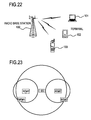
- Fig. 22 depicts an image of the services provided by IEEE 802.16d and IEEE 802.16e. These services are based on a P-MP (Point-to-Multipoint) connection, where a plurality of terminals 101 to 103 are connected to one radio base station 100.
- P-MP Point-to-Multipoint
- IEEE 802.16d or the like is based on the P-MP connection, so the service area is limited to a cover area (cell) covered by the radio base station 100, and the communication rate drops at the cell edge.
- IEEE 802.16j a relay station to relay communication between the radio base station and radio terminals is under consideration (IEEE 802.16j).
- Fig. 23 is a diagram depicting an example of a network configuration of IEEE 802.16j.
- the relay stations RS are disposed in order to improve the communication rates of two radio terminals MS#1 and MS#2, which are located near a cell edge of the radio base station BS.
- the radio terminal MS communicates with the radio base station BS according to MAP information which is sent from the radio base station BS.
- the MAP information For the MAP information, a radio resource which the radio terminal MS uses for communication (frequency channel and time (transmission timing): hereafter called "burst"), modulation method and encoding method of the burst, and communication target radio terminal MS, are specified.
- the MAP information has a DL-MAP message of a downlink direction and a UL-MAP massage of a uplink direction.
- Fig. 24 depicts an example of the DL-MAP message
- Fig. 25 depicts an example of a Burst Profile DL-MAP IE (hereafter called "DL-MAP IE") included in the DL-MAP message.
- DL-MAP IE Burst Profile DL-MAP IE
- One or a plurality of (n in the example of Fig. 24 ) DL-MAP IE(s) is or are inserted in the "DL-MAP_IE for OFDMA PHY" field of the DL-MAP message.
- DL-MAP IE has a "DIUC" field and "CID” field.
- DIUC a code to indicate the modulation method and encoding method (including an encoding rate) of the burst is inserted.
- CID an identifier of a connection of a packet included in the burst is inserted, and the radio terminal MS can select the burst to be decoded by recognizing the CID.
- Fig. 26 depicts an allocation example of a downlink burst by DL-MAP IE. Each burst is specified by a "Symbol Offset" or the like of the DL-MAP IE, and the radio terminal MS communicates to the radio base station BS using the allocated transmission area (frequency (ordinate) and time (abscissa)).
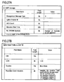
- Fig. 27A depicts an example of the UL-MAP message
- Fig. 27B depicts an example of a Burst Profile UL-MAP IE (hereafter called "UL-MAP IE") included in this message.
- UL-MAP IE Burst Profile UL-MAP IE
- the UL-MAP IE includes "CID”, "UIUC” and "Duration" fields.
- the "CID” field an ID to identify the radio terminal MS, which allocated the burst, is inserted, in the "UIUC” field, a code to indicate the modulation method and encoding method (including the encoding rate) of the burst is inserted, and in the "Duration” field, a band amount (number of slots) to be allocated is inserted.
- Fig. 28A and Fig. 28B depict an allocation example of the uplink burst by the UL-MAP IE.
- allocation of the uplink burst is basically defined by a number of slots.
- each slot is sequentially allocated in the time axis (symbol direction: abscissa) direction, shifting to the next sub-channel (ordinate) at the break point of the Uplink Zone, and the number of slots specified in the "Duration" field are allocated. Then the first slot of the next burst is allocated, continuing from the last slot of the previous burst.
- Fig. 28A and Fig. 28B depict, unlike the case of allocation of the downlink burst which is indicated by a square formed by the number of sub-channels and the number of symbols, allocation of the uplink burst is not very complete.
- each burst is sequentially allocated to the uplink burst in the sequence of UL-MAP IE ("Burst Profile IE Burst #1 " in Fig. 28C ).
- Non-patent Document 1 IEEE Std 802.16-2004
- Non-patent Document 2 IEEE Std 802.16e-2005
- US2006/046643 discloses a wireless communication system in which a base station transmits relay station burst packets and MAP messages including information providing notification of the timing of information transmission and reception.
- JP 2005 252677 discloses a base station comprising a group information storing part for storing group information of a group consisting of at least one communication apparatuses, a radio resource allocating part for allocating at least one different orthogonal code for each group on the basis of the group information and includes information of the orthogonal code in the stored information, a group information transmitting part for transmitting the group information including the allocation information to communication equipment belonging to the group and directly communicable, and an MC-CDMA communicating part for communicating with the directly communicable communication equipment on the basis of the allocation information.
- a radio base station and a communication control method which can appropriately allocate a radio resource when a radio communication is performed between a radio terminal and radio base station via a relay station.
- a radio base station configured to perform data transmission with radio terminals under a plurality of relay stations via the plurality of relay stations respectively, comprising a map information generation unit configured to generate map information indicating an allocation of radio resources for a radio frame, the allocation being such that a first transmission area, from a first relay station to a first radio terminal under the first relay station, and a second transmission area from a second relay station to a second radio terminal under the second relay station, partially or completely overlap; and a transmission unit configured to transmit the map information, wherein the first relay station and second relay station are located at positions in which the first relay station and second relay station do not interfere with each other, and wherein the map information generation unit is configured to specify a modulation and encoding method in the map information so as to match a modulation and encoding method of the first radio terminalto a modulation and encoding method of the second radio terminal, when the modulation and encoding method of the first radio terminal is different from the modulation and encoding method of
- a communication control method in a radio communication system in which data transmission is performed between a radio base station and radio terminals under a plurality of relay stations via the plurality of relay stations respectively, the method comprising transmitting first data, addressed to a first radio terminal under a first relay station, and second data, addressed to a second radio terminal under a second relay station, to the first and second relay station, respectively; and transmitting the first data from the first relay station in a first transmission area and the second data from the second relay station in a second transmission area, so that the first and second transmission areas partially or completely overlap, wherein the first relay station and second relay station are located at positions in which the first relay station and second relay station do not interference with each other, and wherein the radio base station specifies a modulation and encoding method so as to match a modulation and encoding method of the first radio terminal to a modulation and encoding method of the second radio terminal, when the modulation and encoding method of the first radio terminal is different from the modul
- the first embodiment is an example for appropriately allocating a radio resource when radio communication is performed between a radio base station BS and a radio terminal MS via a relay station RS.
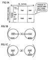
- Fig. 1A depicts an example of a sub-frame in the downlink direction (abscissa is time (transmission timing), ordinate is frequency channel).
- the radio resource is allocated to the relay stations RS#1 and RS#2 to be transmitted simultaneously using half of the frequency band respectively. And the radio resource is allocated to the radio terminals MS#1 and MS#2 to be transmitted simultaneously using half of the frequency band respectively, too.
- a DL-MAP message is set so that the transmission areas (frequency channel and time) do not overlap between each burst.
- data is simultaneously sent from the radio base station BS to each relay station RS#1 and RS#2 using different frequency bands (see Fig. 1B ). Then data is simultaneously sent from each relay station RS#1 and RS#2 to the subordinate radio terminals MS#1 and MS#2 respectively (see Fig. 1C ).
- the independent radio resource is allocated to the radio terminals MS#1 and MS#2 under the relay stations RS#1 and RS#2 respectively, so the radio resource can be appropriately allocated.
- the radio resource is allocated to the relay stations RS and the subordinate radio terminals MS such that the respective transmission areas (frequency channel, transmission timing) do not overlap.
- the different radio resource is allocated respectively.
- the radio base station BS manages relay stations RS which do not interfere with each other, and concerning the allocation of a downlink burst (allocation of a radio resource in the downlink direction) to the radio terminals MS which communicate with a same burst profile (combination of a modulation method and encoding method) out of the radio terminals MS under such relay stations RS, the radio base station BS generates and sends DL-MAP where the downlink burst is allocated to same burst area (transmission area) in a downlink sub-frame (symbol time and frequency channel (sub-channel)). Since a same transmission area (frequency channel) can be used simultaneously for a plurality of radio terminals MS, utilization efficiency of the frequency can be improved.
- the allocation of the radio resource in the uplink direction will be described in detail in the fifth embodiment.
- the radio communication system has the radio terminal MS, plurality of relay stations RS, and radio base stations BS under the relay stations RS.
- the second exemplary embodiment will now be described in concrete terms with reference to Fig. 2 to Fig. 7 .
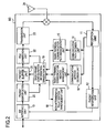
- Fig. 2 is a block diagram depicting a configuration example of the radio base station BS according to the second exemplary embodiment.
- the radio base station BS has a reception unit 11, packet regeneration unit 12, NW interface unit 13, communication path decision unit 14, radio terminal communication path management unit 15, communication method decision unit 16, radio terminal communication method management unit 17, non-interference relay station management unit 18, radio frame configuration information generation unit 19, packet identification unit 20, packet buffer unit 21, PDU generation unit 22 and transmission unit 23.
- the reception unit 11 outputs it to the packet regeneration unit 12, when a PDU (Protocol Data Unit), including user data is received via an antenna 24.
- PDU Protocol Data Unit
- the PDU is reconstructed into an IP (Internet Protocol) packet or the like, and is transferred to the host network via the NW interface unit 13.
- the reception unit 11 also outputs to the communication method decision unit 16 radio channel performance information (e.g. CINR: Carrier to Interface and Noise Ratio) of the downlink, which the radio terminal MS measured and fed back, radio channel information of the uplink measured by the reception unit 11, or radio channel performance information of the uplink which the relay station RS measured and transferred.
- radio channel performance information e.g. CINR: Carrier to Interface and Noise Ratio
- the communication method decision unit 16 decides a communication method (modulation method, error correction encoding method, encoding rate) for each radio terminal MS based on the radio channel performance information, and outputs this information to the radio terminal communication method management unit 17.
- the radio terminal communication method management unit 17 holds a radio terminal communication method management table T1 and stores this information.
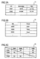
- Fig. 3A is an example of the radio terminal communication method management table T1.
- the modulation method "Modulation” to be used e.g. QPSK, 16QAM
- error correction code encoding method "FEC” Forward Error Correction (e.g. convolutional code, turbo code), and encoding rate (e.g. 1/2, 3/4) are indicated for each radio terminal MS.
- a combination of communication methods with which fast communication is possible is selected if the radio channel performance is good, and a combination of communication methods with which slower communication is possible is selected if the radio channel performance is not good.
- AMC Adaptive Modulation Control
- the communication path decision unit 14 decides an optimum communication path in terms of effective use of the radio resource, based on the respective radio channel performance information between the radio terminal MS, radio base station BS and relay station RS, transferred from the reception unit 11, and outputs this information to the radio terminal communication path management unit 15.
- a path that passes through the relay station RS1 is selected.
- the radio terminal communication path management unit 15 holds a radio terminal communication path management table T2, and stores this information.
- Fig. 3B is an example of the radio terminal communication path management table T2.
- the optimum communication path of the radio terminal MS#1 is communication via the relay station RS#1
- the optimum communication path of the radio terminal MS#3 is direct communication with the radio base station BS.
- the non-interference relay station management unit 18 recognizes the presence of interference among each relay station RS when the relay stations RS are positioned, and stores this information in a non-interference relay station management table T3.
- Fig. 3C depicts an example of the non-interference relay station management table T3. This example depicts that the relay station RS#1 and the relay station RS#2 do not interfere with each other. For this information, the presence of interference may be judged based on the carrier sense by the relay station RS on a radio signal from a neighborhood relay station RS, or on a report on CINR of a receive signal from the neighborhood relay station RS of a subordinate radio terminal MS, and stored in table T3.
- a receive signal from the neighborhood relay station RS has a predetermined level or more, it is regarded as the presence of interference, or if the CINR report from the radio terminal MS indicates that a signal having CINR exceeding a reference value is received from a neighborhood station, it is regarded as the presence of interference.
- the NW interface unit 13 receives an IP packet or the like from the host network, and outputs it to the packet identification unit 20.
- the packet identification unit 20 identifies a destination radio terminal MS and QoS (Quality of Service) class based on such information of the IP header, and requests band allocation to the radio frame configuration information generation unit 19, and outputs the IP packet or the like to the packet buffer unit 21.
- the CID is specified by identifying the destination radio terminal MS.
- the radio frame configuration information generation unit 19 acquires the communication method (modulation method, error correction code) of the radio terminal MS corresponding to each CID for which a band allocation is requested, from the radio terminal communication method management table T1 of the radio terminal communication method management unit 17.
- the radio frame configuration information generation unit 19 acquires the information whether direct communication with the radio base station BS or communication via the relay station RS is performed, and the information on the relay station RS to be the target if communication via the relay station RS is used, based on the radio terminal communication path management table T2 of the radio terminal communication path management unit 15.
- the radio frame configuration information generation unit 19 also acquires information on the presence of mutual interference between the target relay station RS based on the non-interference relay station management table T3 in the non-interference relay station management unit 18.
- the radio frame configuration information generation unit 19 Based on this information, the radio frame configuration information generation unit 19 generates the DL-MAP message which defines a band allocation of the radio frame, and sends it via the PDU generation unit 22 and transmission unit 23, and reads the required data packet addressed to the relay station RS and radio terminal MS from the packet buffer unit 21, and sends it via the PDU generation unit 22 and transmission unit 23.
- Fig. 4 is a flow chart depicting the band allocation processing to the radio terminal MS, which is performed in the radio base station BS. This processing is executed by the radio frame configuration information generation unit 19.
- the radio base station BS judges whether it is a band allocation timing for the radio terminal MS (S11). Whether it is the allocation timing or not is judged depending on whether a time to create map information for each frame (e.g. time to create map information for one frame) has come or not.
- the radio base station BS waits until this timing comes.
- the radio base station BS extracts candidate radio terminals MS to which the band is allocated (S12). The candidates are extracted from destination radio terminals MS from the packet identification unit 20.
- the band is allocated to the radio terminal MS which directly communicates with the radio base station BS, selected out of the candidate radio terminals MS (S14).
- the transmission area in the downlink direction, which is allocated to this radio terminal MS is defined.
- Radio terminals MS, under a non-interference relay station, are grouped (S15) by searching the non-interference relay station management table T3.
- the radio terminal MS group is subdivided into groups of radio terminals MS that use the same communication method (modulation method and error code encoding method) (S16).
- the same radio resource is allocated to the radio terminals MS in a same group (S17).
- a same transmission area in the downlink direction is defined to the radio terminals MS belonging to the same group.
- data is directly transmitted from the radio base station BS to the radio terminal MS, or data having different content is sent from a plurality of relay stations RS to each subordinate radio terminal MS.
- relay stations RS1, RS2 and RS3 which do not interfere with each other, exist, and radio terminals MS11 and MS12 exist under the relay station RS1, radio terminals MS21 and MS22 exist under the relay station RS2, and radio terminal MS31 exists under the relay station RS3.
- radio terminals MS11, MS21, and MS31 correspond to the same communication method
- radio terminals MS22 and MS32 correspond to the same communication method
- the transmission area in the downlink direction is defined in DL-MAP
- the transmission area (transmission timing, transmission sub-channel) in the downlink direction of MS11, MS21 and MS31 at least partially overlaps. It is preferable that the transmission area is the same. Also the transmission band (transmission timing, transmission sub-channel) in the downlink direction of MS12 and MS22 at least partially overlaps (including the case of one transmission area being included in the other transmission area). It is preferable that the transmission area is the same.
- the same radio resource can be allocated to the radio terminals MS which use the same communication method when the radio terminals MS are under relay stations RS which do not interfere with each other, out of a plurality of relay stations RS.
- Fig. 5A depicts an example of DL-MAP IE generated by the band allocation processing
- Fig. 5B depicts an example of the downlink sub-frame.
- DL-MAP IE depicted in Fig. 5A two CIDs (the CID of radio terminal MS#1 and the CID of radio terminal MS#2) are defined in one DL-MAP IE which defines one transmission area, and as Fig. 5B depicts, two radio terminals, MS#1 and MS#2, are placed in one burst by "Symbol Offset" or the like. In one burst, it is allowable to send data from different relay stations RS (RS#1 and RS#2 in this case) to a plurality of subordinate radio terminals MS (radio terminals MS#1 and MS#2 in this case) respectively.
- RS relay stations
- the two radio terminals MS#1 and MS#2 communicate using the common modulation method and error correction code.
- the frames shown by RS#1 and RS#2 indicate an MMR link between the radio base station BS and relay station RS#1, and an MMR link between the radio base station BS and relay station RS#2 respectively. It is preferable that the radio base station sends data addressed to the radio station MS to each relay station RS using MMR of the sub-frame in a same transmission band of the burst shown in MS#1 and MS#2. In other words, data for MS#1 is stored in RS#1 and data for MS#2 is stored in RS#2, and are sent.
- the two radio terminals MS#1 and MS#2 receive the DL-MAP from the radio base station BS respectively, receive the burst defined by DL-MAP IE from the relay stations RS#1 and RS#2 respectively, demodulate and decode, and receive a respective data packet to which the CID addressed to itself is attached.
- this burst data packets are simultaneously sent from different relay stations, but these relay stations do not interfere with each other, so each radio terminal MS#1 and MS#2 can perform receive processing normally.
- Each relay station RS must relay only the data addressed to its subordinate radio terminals MS. Therefore even if the DL-MAP message shows that data addressed to a plurality of radio terminals MS exists, each relay station RS actually sends only the data addressed to its subordinate radio terminal MS.
- Fig. 6A and Fig. 6B depicts an example when communication is performed using DL-MAP IE depicted in Fig. 5A and Fig. 5B .
- the radio base station BS sends data to two relay stations, RS#1 and RS#2, simultaneously (same symbols), using different frequency channels (see Fig. 6A ).
- each relay station RS#1 and RS#2 sends the data to the respective subordinate radio terminals MS#1 and MS#2 simultaneously using a common frequency channel (sub-channel) (see Fig. 6B ).
- the band utilization efficiency can be improved.
- the data addressed to the radio terminals MS#1 and MS#2 may be sent by the relay stations RS#1 and RS#2 in advance in a radio frame immediately before this radio frame. This is because the processing delays of the relay stations RS#1 and RS#2 (e.g. processing delay to analyze such a control message as DL-MAP) are considered.
- the bursts addressed to the relay stations RS#1 and RS#2 are depicted in Fig. 5B as if they were defined independently from each other, but both may be defined as one burst if the two relay stations RS#1 and RS#2 communicate using a same modulation method and error correction encoding method.
- the relay station RS has a reception unit 31, control message extraction unit 32, PDU buffer unit 33, transmission unit 34, MAP information analysis unit 35 and control message generation unit 36.
- the reception unit 31 outputs uplink radio channel performance information measured by a signal from the radio terminal MS, and downlink radio channel performance information fed back from the radio terminal MS to the control message generation unit 36, and outputs other user data and control messages (e.g. DL-MAP message) to the control message extraction unit 32.
- DL-MAP message user data and control messages
- the control message generation unit 36 generates a control message to send the radio channel performance information from the reception unit 31 to the radio base station BS, and stores them in the PDU buffer unit 33.
- the stored control message is sent to the transmission unit 34 frame by frame, and is sent to the radio terminal MS.
- the control message extraction unit 32 outputs the control message to the MAP information analysis unit 35, and outputs the user data to the PDU buffer unit 33.
- the MAP information analysis unit 35 analyzes such a control message as the DL-MAP, so that the transmission data from the radio base station BS (data transmitted via an MMR link) based on this analysis result, and sends the relay data (user data), stored in the PDU buffer unit 33, to the subordinate radio terminal MS.
- the relay data to the radio terminal MS may be received by another control message immediately before receiving DL-MAP, considering the processing delay to analyze DL-MAP.
- the reception unit 31 receives only data to the subordinate radio terminal MS of this relay station RS, out of the data sent from the radio station BS, and discards other data received.
- radio resources for a plurality of radio terminals MS are allocated to one burst in the DL-MAP message, but this merely sends data only to the subordinate radio terminals MS from the point of view of each relay station RS.
- two radio terminals MS are defined in one burst, but needless to say, three or more radio terminals MS can be defined if three or more relay stations RS which do not interfere with each other exist. In this case as well, the same radio resource is allocated to each radio terminal MS, so utilization efficiency of the radio resource can be improved.
- Fig. 8 depicts a distribution example of radio terminals MS.
- the radio terminals MS#1, MS#2 and MS#3 are located at the cell edges of relay stations RS. It is assumed that the relay stations RS#1 and RS#2 and these radio terminals MS#1, MS#2 and MS#3 perform communication by QPSK. It is also assumed that the radio terminal MS#4, which is located near the relay station RS#2, performs communication by 16QAM, whereby fast communication is possible. And it is assumed that the data volume which each relay station RS sends to each radio terminal MS is the same. In this case, the data addressed to the radio terminal MS#4 can be sent using the radio resource (number of sub-channels), half that of other radio terminals MS. The relay stations RS#1 and RS#2 do not interfere with each other.
- Fig. 9A depicts an example of DL-MAP information and data transmission. Since the three radio terminals MS#1, MS#2 and MS#3 use a common QPSK communication method, MS#3 can use the same transmission area as MS#1 and (or) MS#2. In Fig. 9A , MS#1 and MS#3 use the same transmission area (same transmission timing, same transmission sub-channel).
- a different resource is allocated to the radio terminal MS#4 however.
- the transmission timing of MS#4 is the same as the transmission timing of MS#3.
- the transmission sub-channel is different from the transmission sub-channels used by MS#1. MS#2 and MS#3.
- the radio terminal MS#4 is not the subordinate radio terminal MS, and the transmission area X allocated to the radio terminal MS#4 is not used.
- a band Y which is a band other than the band allocated to the radio terminal MS#3 among from the bands of QPSK is not used.
- the radio terminal MS#4 is changed to communication based on QPSK, as depicted in Fig. 9B , so that the radio resource used for the radio terminal MS#4 depicted in Fig. 9A can be used for the radio base station BS (e.g. radio terminals MS under the radio base station BS) and other relay stations RS, whereby utilization efficiency of the radio resource can be improved.
- the radio base station BS e.g. radio terminals MS under the radio base station BS
- other relay stations RS e.g. radio terminals MS under the radio base station BS
- Fig. 10 is a flow chart depicting the transmission area allocation processing which is executed by the radio base station BS. This processing is executed in the radio frame configuration information generation unit 19. Processing from S21 to S26 is the same as the processing from S11 to S16 of Fig. 4 . In the radio terminals MS under the non-interference relay stations RS, radio terminals MS using the same modulation method and same error correction encoding method are grouped.
- the same radio resource is allocated to radio terminals MS in a group to which the radio resource is not allocated, and which uses the modulation method and error correction encoding group having a lowest multi-value degree (S27).
- the multi-value degree is low in the case of QPSK, and the multi-value degree is high in the case of 16QAM. This can be judged by storing the multi-value degree when the modulation method and error correction encoding method are combined in the radio base station BS, and referring to it in this processing.
- the multi-value degree of the group of QPSK is lowest, so the radio resource is allocated first to the group of QPSK.
- the same radio resource is allocated to radio terminals MS, which are under the relay station RS of which actual use amount is low, and to which the radio resource is not allocated (S29).
- the radio resource the same as that of the group of QPSK is allocated to the radio terminal MS#4 under the relay station RS#2 of which actual use amount is low.
- Fig. 9B depicts an example of the DL-MAP information when the same radio resource is allocated.
- the MS#4 uses QPSK as the communication method, in spite of being judged that communication using QAM can be performed by adaptive modulation control
- the processing moves to S27, and the above mentioned processing is repeated. If there is no radio terminal MS to which the radio resource is not allocated (Y in S30), it is judged whether an un-allocated band exists (S31). If the un-allocated band exists (N), the processing moves to S22, and if the un-allocated band does not exist (Y in S31), creation of the DL-MAP is completed, and the DL-MAP is sent.
- data addressed to each radio terminal is sent from the radio base station BS to the corresponding relay station RS so that the data can be sent in the transmission area defined in the DL-MAP, and each relay station sends the data addressed to the radio terminal, which is received from the radio base station BS in the transmission area defined in the DL-MAP.
- the radio resource of the radio terminal MS having a low multi-value degree is allocated to the radio terminal MS having a high multi-value degree.
- the fourth embodiment is an example when the radio resource of the radio terminal MS having the high multi-value degree is allocated to the radio terminal MS having the low multi-value degree.
- Fig. 11 depicts a distribution example of the radio terminals MS.
- radio terminals MS#1 and MS#2 are located at the cell edges of the relay station RS#1. For these radio terminals MS#1 and MS#2, QPSK communication is performed.
- Radio terminals MS#3 and MS#4 are located near the relay station RS#2. For these radio terminals MS#3 and MS#4, 16QAM communication is performed.
- the data amount to be sent to each radio terminal MS is the same. Data addressed to the radio terminals MS#3 and MS#4 can be sent using the radio resource half that for the data addressed to radio terminals MS#1 and MS#2.
- the different radio resource is allocated in the DL-MAP information, for the group of the radio terminals MS#1 and MS#2 which perform QPSK communication, and for the group of the radio terminals MS#3 and MS#4 which perform 16QAM communication as depicted in Fig. 12A .
- the band Z allocated to the radio terminals MS#3 and MS#4 is not used, and for the transmission of the relay station RS#2, the band U allocated to the radio terminals MS#1 and MS#2 is not used.
- the radio resource the same as that of the radio terminals MS#3 and MS#4 which perform 16QAM communication having a high multi-value degree is allocated to the radio terminals MS#1 and MS#2 which perform QPSK communication having a low multi-value degree, as depicted in Fig. 12B . Therefore just like the case of the third embodiment, utilization efficiency of the radio resource can be improved.
- the radio band used for the QPSK communication in Fig. 12A can be allocated to other relay stations RS and radio base stations BS, and the utilization efficiency of the radio resource can be improved in this aspect as well.
- the transmission power is increased for the radio terminals MS#1 and MS#2 which perform 16QAM communication. This is for communicating with the radio terminals MS#1 and MS#2 located at the cell edge with certainty.
- Fig. 13 is a flow chart depicting a band allocation processing for radio terminals MS. This processing is executed in the radio frame configuration information generation unit 19. The processing from S41 to S46 is the same as the processing from S21 to S26 of Fig. 10 . In the radio terminals MS under the non-interference relay stations RS, radio terminals MS using the same modulation method and same FEC are grouped.
- the same radio resource is allocated to radio terminals MS in a group to which the radio resource is not allocated, and which uses the modulation method and FEC having a highest multi-value degree (S47).
- the same radio resource is allocated to the radio terminals MS#3 and MS#4.
- a transmission power to radio terminals MS which are under the relay station RS of which actual use amount is low and to which the radio resource is not allocated, is increased, and the same radio resource is allocated (S49).
- the radio resource the same as that of the radio terminals MS#3 and MS#4 is allocated to the radio terminals MS#1 and MS#2.
- the relay station RS#1 is instructed to increase the transmission power when communication is performed with the radio terminals MS#1 and MS#2.
- S50 it is judged whether there is the radio terminal MS to which the radio resource is not allocated, and if there is no un-allocated radio terminal MS (Y in S50), it is judged whether an un-allocated band exists (S51). If there is the un-allocated radio terminal MS (N in S50), processing moves to S47. If there is the un-allocated band (Y in S51), the processing moves to S41, and the above mentioned processing is repeated. If there is no un-allocated band (N in S51), creation of DL-MAP is completed and the DL-MAP is sent.
- data addressed to each radio terminal is sent from the radio base station BS to the corresponding relay station RS so that the data can be sent in the transmission area defined in the DL-MAP, and each relay station sends the data addressed to the radio terminal, which is received from the radio base station BS in the transmission area defined in the DL-MAP.
- Fig. 14 depicts a block diagram depicting a configuration example of the radio base station BS according to the fourth exemplary embodiment. The difference from the configuration of the radio base station BS depicted in Fig. 2 is that a relay station transmission power control information generation unit 25 is added.
- the relay station transmission power control information generation unit 25 When an instruction to increase the transmission power of the relay station RS is received from the radio frame configuration information generation unit 19, the relay station transmission power control information generation unit 25 generates a control information message, to instruct control information to increase the transmission power to this relay station RS.
- the generated control information message is stored in the packet buffer unit 21, and is sent according to the instruction of the radio frame configuration information generation unit 19.
- the power control of the relay station RS can also be performed using Boosting information included in the DL-MAP IE (See Fig. 25 ).
- the relay station transmission power control information generation unit 25 receives an instruction to decrease the transmission power from the radio frame configuration information generation unit 19, and sends the control information to decrease the transmission power to the relay station RS.
- the control information to control the transmission power is analyzed by the MAP information analysis unit 35, and the transmission unit 34 is instructed to increase or to decrease the transmission power, and based on this instruction, the transmission unit 34 adjusts the transmission power and sends the data to the radio terminal MS.
- the fifth exemplary embodiment is an example of an uplink. It is the same as the second to fourth exemplary embodiments to improve utilization efficiency of the radio resource and utilization efficiency of the frequency by allocating the same transmission area to the radio terminals MS under relay stations RS which do not interfere with each other.
- each burst based on the UL-MP message is defined by the number of slots, so each burst is not located at an absolute position, but at a relative position (see Fig. 28A ). Also only one CID can be specified in the UL-MAP message. Therefore a plurality of radio terminals MS cannot be located in one burst, and allocating a plurality of radio terminals MS in one uplink side transmission area is difficult.
- the fifth exemplary embodiment at least a part, but preferably all, of the transmission area from the radio terminal MS to the relay station RS direction and the transmission area from another relay station which does not interfere to the radio base station overlap.
- Allocation of the transmission area from the radio terminal MS to the relay station RS is performed using a part of the UL-MAP message, and allocation of the transmission area from the relay station RS to the radio base station BS is performed using another part of the UL-MAP message (called an RS-MAP).
- the different transmission area e.g. transmission time zone
- the different transmission area e.g. transmission time zone
- the common radio band can be allocated to different transmission devices, and utilization efficiency of the frequency can be improved, just like the second embodiment.
- Fig. 15 is a block diagram depicting a configuration example of the radio base station BS according to the fifth embodiment. Compared with the block configuration of the radio base station BS depicted in Fig. 2 , the radio base station BS further has a control information extraction unit 26, band request analysis unit 27, and relay station band allocation information generation unit 28.
- the control information extraction unit 26 extracts a band request from the reception unit 11 (a band request from the relay station RS or radio terminal MS), and outputs it to the band request analysis unit 27.
- the band request analysis unit 27 outputs UL-MAP message creation request information corresponding to the band request to the radio frame configuration information generation unit 19.
- the radio frame configuration information generation unit 19 creates the UL-MAP message.
- Information for creating the UL-MAP is acquired from the radio terminal communication path management unit 15, radio terminal communication method management unit 17 and non-interference relay station management unit 18, just like the second embodiment.
- the radio frame configuration information generation unit 19 outputs information on the UL-MAP to the relay station band allocation information generation unit 28.
- the relay station band allocation information generation unit 28 When the information on UL-MAP is received, the relay station band allocation information generation unit 28 generates an RS-MAP message (relay station band allocation information), and sends it to the relay station RS via the packet buffer unit 21.
- Fig. 16A depicts an example of the RS-MAP message
- Fig. 16B depicts an example of Burst Profile RS-MAP IE (hereafter "RS-MAP IE") included in the RS-MAP message.
- RS-MAP IE Burst Profile RS-MAP IE
- the relay station RS to be a target is specified by "CID”
- the burst is specified by "Symbol Offset” or the like, and the radio resource is allocated.
- a plurality of "CIDs” may be specified, just like the case of DL-MAP IE.
- Fig. 17A and Fig. 17B depict a same transmission area in a same transmission sub-frame respectively (MAP data is omitted).
- band allocation for uplink (for relay station RS#1) to the radio terminal MS#1 under the relay station RS#1 is performed in time zone Zone#1, and at the same time, band allocation for uplink (for radio base station BS) to the relay station RS#2, which does not interfere with the relay station RS#1, is performed.
- band allocation for transmission to the relay station RS#2, to the radio terminal MS#2 under the relay station RS#2 is performed, and band allocation for transmission to the radio base station BS, to the relay station RS#1, which does not interfere with the relay station RS#2, is performed.
- the UL-MAP message is created and sent so that the radio resource is allocated in this way.
- a number of slots is defined in the UL-MAP message (see Fig. 27B ), so the band for each radio terminal MS is allocated to the burst at a predetermined position based on this number of slots.
- Fig. 17C and Fig. 17D depict a communication status in each time zone.
- the radio terminal MS#1 sends data to the relay station RS#1, and the relay station RS#2 also sends to the radio base station BS at the same time using the same radio resource.
- the relay station RS#1 sends data to the radio base station BS, and the radio terminal MS#2 sends data to the relay station RS#2 at the same time using the same radio resource.
- Fig. 18 is a flow chart depicting the band allocation processing in the radio frame configuration information generation unit 19. The processing from S61 to S65 is the same as the processing from S11 to S15 of the second embodiment in Fig. 4 .
- the radio frame configuration information generation unit 19 allocates bands to radio terminals MS under each group using a different time zone depending on the respective group (S66). In the case of the above mentioned example, the same radio resource is allocated to the radio terminal MS#1 and relay station RS#2, and the same resource is allocated to the radio terminal MS#2 and relay station RS#1.
- Fig. 19 is a flow chart depicting processing in the relay station band allocation information generation unit 28 of the radio base station BS.
- the band in the time zone, where the band is allocated to the radio terminal MS under another non-interfering relay station RS is allocated to the relay station RS (S72).
- the band in the time zone Zone#1, where the band is allocated to the radio terminal MS#1 under another non-interfering relay station RS#1 is allocated to the relay station RS#2. This corresponds to the RS-MAP message generation processing.
- the processing stands by until the information is received.
- the fifth exemplary embodiment can be applied to the third and fourth exemplary embodiments.
- a plurality of CIDs are specified in DL-MAP IE ( Fig. 5A ), and a same transmission area is allocated to a plurality of radio terminals MS.
- one CID is specified for one DL-MAP IE, and a same value is set for "Symbol Offset" of each DL-MAP IE, and a different value is specified for "DIUC".
- the same transmission area is allocated to each radio terminal MS, and the modulation method, encoding method, and encoding rate thereof can be specified to be different from each other.
- the data transmission matching the position of a radio terminal MS in the cell can be performed. For certain the same transmission area is allocated to each radio terminal MS, so utilization efficiency of the frequency can be improved.
- Fig. 20 is a flow chart depicting the processing in the radio frame configuration information generation unit 19 according to the sixth examplary embodiment. Processing from S81 to S84 is the same as the processing from S11 to S14 of the second embodiment ( Fig. 4 ).
- radio terminals MS under a non-interfering relay station RS are extracted by searching the non-interference relay station management table T3, and are grouped for each relay station RS to be connected.
- radio terminals MS are distributed as depicted in Fig. 6A , the radio terminal MS#1 and radio terminal MS#2 are grouped separately.
- the band is allocated to the radio terminals MS in each group (S86).
- the band is allocated to the radio terminal MS#1 and radio terminal MS#2 using the same transmission area.
- Fig. 21A and Fig. 21B depict an example of DL-MAP allocation.
- the two radio terminals MS#1 and MS#2 are allocated to a same burst.
- Fig. 21C and Fig. 21D depicts a downlink transmission example when this allocation is performed.
- Data is sent from the radio base station BS to the relay stations RS#1 and RS#2 which do not interfere with each other, at a same time, and data is transmitted to the radio terminals MS#1 and MS#2 under each relay station RS#1 and RS#2 at a same time using the different modulation method.
- downlink is described, but this embodiment can also be applied to uplink.
- the sixth embodiment can also be applied to the third and fourth embodiments. In either case, a same transmission area can be allocated to the radio terminals MS under non-interfering relay stations RS, and data can be sent to the radio terminals MS using the different modulation method.
- the transmission area is shared by different transmission devices, but the transmission area to be shared need not be exactly the same.
- the transmission areas may partially overlap in time, or the transmission sub-channels to be used may partially overlap.
- the transmission start timing of the transmission area matches , and transmission end timing is allowed to be different in each transmission device.
Landscapes
- Engineering & Computer Science (AREA)
- Computer Networks & Wireless Communication (AREA)
- Signal Processing (AREA)
- Mobile Radio Communication Systems (AREA)
Claims (7)
- Station de base radio configurée pour réaliser la transmission de données avec des terminaux radio sous le contrôle d'une pluralité de stations de relais par le biais de la pluralité de stations de relais respectivement, comprenant :une unité de génération d'informations cartographiques (19) configurée pour générer des informations cartographiques indiquant une affectation des ressources radio pour une trame radio, l'affectation étant telle qu'une première zone de transmission, d'une première station de relais vers un premier terminal radio sous le contrôle de la première station de relais, et qu'une seconde zone de transmission, d'une seconde station de relais vers un second terminal radio sous le contrôle de la seconde station de relais, se chevauchent partiellement ou complètement ; etune unité de transmission configurée pour transmettre les informations cartographiques,dans laquelle la première station de relais et la seconde station de relais sont situées à des positions dans lesquelles la première station de relais et la seconde station de relais n'interfèrent pas l'une avec l'autre, etdans laquelle l'unité de génération d'informations cartographiques (19) est configurée pour spécifier un procédé de modulation et de codage dans les informations cartographiques afin d'adapter un procédé de modulation et de codage du premier terminal radio à un procédé de modulation et de codage du second terminal radio, lorsque le procédé de modulation et de codage du premier terminal radio est différent du procédé de modulation et de codage du second terminal radio.
- Station de base radio selon la revendication 1, dans laquelle la zone de transmission chevauchée est un canal de fréquences.
- Station de base radio selon la revendication 1, dans laquelle un même procédé de modulation et de codage sont utilisés dans la partie chevauchée.
- Station de base radio selon la revendication 1, dans laquelle l'unité de génération d'informations cartographiques (19) est configurée pour générer des informations de commande pour modifier la puissance de transmission pour envoyer les données de la première station de relais vers le premier terminal radio, et envoie les informations de commande à la première station de relais.
- Station de base radio selon la revendication 1, dans laquelle l'unité de génération d'informations cartographiques est configurée pour spécifier indépendamment un procédé de modulation et un procédé de codage du premier terminal radio, et un procédé de modulation et procédé de codage du second terminal radio dans les informations cartographiques.
- Station de base radio selon la revendication 1,
dans laquelle l'unité de génération d'informations cartographiques (19) est configurée pour définir la transmission de la première station de relais vers un premier terminal radio sous le contrôle de la première station de relais, et la transmission de la seconde station de relais vers un second terminal radio sous le contrôle de la seconde station de relais, dans des informations cartographiques pour définir une zone de transmission. - Procédé de commande de communication dans un système de transmission radio, dans lequel la transmission de données est réalisée entre une station de base radio et des terminaux radio sous le contrôle d'une pluralité de stations de relais par le biais de la pluralité de stations de relais respectivement, le procédé comprenant :la transmission de premières données, adressées à un premier terminal radio sous le contrôle d'une première station de relais, et de secondes données, adressées à un second terminal radio sous le contrôle d'une seconde station de relais, à la première et seconde station de relais, respectivement ; etla transmission des premières données de la première station de relais dans une première zone de transmission, et des secondes données de la seconde station de relais dans une seconde zone de transmission, de telle sorte que les première et seconde zones de transmission se chevauchent partiellement ou complètement,dans lequel la première station de relais et la seconde station de relais sont situées à des positions dans lesquelles la première station de relais et la seconde station de relais n'interfèrent pas l'une avec l'autre, etdans lequel la station de base radio spécifie (S29 ; S49) un procédé de modulation et de codage afin d'adapter un procédé de modulation et de codage du premier terminal radio à un procédé de modulation et de codage du second terminal radio, lorsque le procédé de modulation et de codage du premier terminal radio est différent du procédé de modulation et de codage du second terminal radio.
Applications Claiming Priority (1)
| Application Number | Priority Date | Filing Date | Title |
|---|---|---|---|
| PCT/JP2006/320506 WO2008044318A1 (fr) | 2006-10-13 | 2006-10-13 | Station de base radio, station relais et procédé de commande de communication |
Publications (3)
| Publication Number | Publication Date |
|---|---|
| EP2059059A1 EP2059059A1 (fr) | 2009-05-13 |
| EP2059059A4 EP2059059A4 (fr) | 2012-12-26 |
| EP2059059B1 true EP2059059B1 (fr) | 2013-12-25 |
Family
ID=39282530
Family Applications (1)
| Application Number | Title | Priority Date | Filing Date |
|---|---|---|---|
| EP06811779.5A Ceased EP2059059B1 (fr) | 2006-10-13 | 2006-10-13 | Station de base radio et procédé de commande de communication |
Country Status (5)
| Country | Link |
|---|---|
| US (1) | US8553607B2 (fr) |
| EP (1) | EP2059059B1 (fr) |
| JP (1) | JPWO2008044318A1 (fr) |
| CN (1) | CN101523943A (fr) |
| WO (1) | WO2008044318A1 (fr) |
Families Citing this family (29)
| Publication number | Priority date | Publication date | Assignee | Title |
|---|---|---|---|---|
| JP4751804B2 (ja) * | 2006-10-20 | 2011-08-17 | 富士通株式会社 | 通信中継装置、通信中継制御方法および通信中継制御プログラム |
| WO2008078394A1 (fr) | 2006-12-26 | 2008-07-03 | Fujitsu Limited | Procédé de communication sans fil, station de contrôle sans fil et station de base sans fil |
| KR101373021B1 (ko) * | 2007-05-10 | 2014-03-13 | 삼성전자주식회사 | 중계 장치를 이용한 이동 단말의 통신 방법 및 그 장치 |
| KR100956726B1 (ko) * | 2007-07-20 | 2010-05-06 | 삼성전자주식회사 | 비동기적으로 수신한 맵 정보 또는 데이터에 발생한 오류를 검출하는 릴레이 |
| KR101433948B1 (ko) * | 2008-03-05 | 2014-08-26 | 삼성전자주식회사 | 통신 시스템에서 신호 송수신 시스템 및 방법 |
| JP5525141B2 (ja) * | 2008-05-19 | 2014-06-18 | 日本テレビ放送網株式会社 | デジタル放送システム、及びデジタル放送方法 |
| JP5114313B2 (ja) * | 2008-06-24 | 2013-01-09 | 京楽産業.株式会社 | データ通信システム及びデータ通信方法 |
| US8355734B2 (en) | 2008-08-07 | 2013-01-15 | Apple Inc. | Wireless system |
| JP2010074471A (ja) * | 2008-09-18 | 2010-04-02 | Hitachi Kokusai Electric Inc | 無線送受信装置 |
| WO2010034341A1 (fr) * | 2008-09-24 | 2010-04-01 | Telefonaktiebolaget L M Ericsson (Publ) | Procédé et mécanisme de commande d’un répéteur dans un système de communication sans fil |
| US20100112178A1 (en) | 2008-10-31 | 2010-05-06 | Fillmore Daniel T | High protein crispy food product and method for preparing the same |
| CN101741452B (zh) * | 2008-11-07 | 2013-09-25 | 华为技术有限公司 | 中继传输方法和网络节点 |
| RU2486711C2 (ru) | 2008-11-07 | 2013-06-27 | Хуавэй Текнолоджиз Ко., Лтд. | Способ ретрансляционной передачи и сетевой узел |
| US8243648B2 (en) * | 2008-12-19 | 2012-08-14 | Intel Corporation | Spatial reuse techniques with wireless network relays |
| JP5225114B2 (ja) * | 2009-01-08 | 2013-07-03 | 三菱電機株式会社 | 通信システム |
| KR101075964B1 (ko) * | 2009-02-02 | 2011-10-21 | 아주대학교산학협력단 | 통신 시스템에서 다중 링크 중계 장치 및 방법 |
| JP5814225B2 (ja) * | 2009-04-17 | 2015-11-17 | アルカテル−ルーセント | リレー・ユーザ選択およびダウンリンク・リソース割当の方法、装置、およびデバイス |
| US9432991B2 (en) * | 2009-04-21 | 2016-08-30 | Qualcomm Incorporated | Enabling support for transparent relays in wireless communication |
| WO2010146674A1 (fr) * | 2009-06-17 | 2010-12-23 | 富士通株式会社 | Station de base, station de relais, système de communication et procédé de communication |
| FR2948252B1 (fr) * | 2009-07-20 | 2011-09-16 | Commissariat Energie Atomique | Methode d'allocation de ressources de transmission dans un reseau cellulaire de type cooperatif |
| CN101990246B (zh) * | 2009-08-04 | 2015-01-28 | 中兴通讯股份有限公司 | 一种下行/上行帧信道分配消息的生成方法及装置 |
| JP5441172B2 (ja) | 2010-05-19 | 2014-03-12 | 日本電気株式会社 | 無線ネットワーク中継装置及び無線ネットワーク中継装置の変調方法並びにコンピュータプログラム |
| WO2012115229A1 (fr) * | 2011-02-25 | 2012-08-30 | シャープ株式会社 | Système de communication sans fil, dispositif de station de base, et procédé de sélection d'un itinéraire de communication sans fil |
| US8614956B2 (en) | 2011-03-10 | 2013-12-24 | Qualcomm Incorporated | Placement of wireless repeaters in a wireless communication network |
| CN102821471B (zh) * | 2011-06-07 | 2017-10-27 | 中兴通讯股份有限公司 | 向多个终端发送数据的方法及装置 |
| IN2014MN02189A (fr) * | 2012-04-22 | 2015-09-11 | Elta Systems Ltd | |
| WO2016209136A1 (fr) * | 2015-06-26 | 2016-12-29 | Telefonaktiebolaget Lm Ericsson (Publ) | Appareils et procédés pour relayer des données dans un réseau de communication sans fil |
| EP3742627B1 (fr) * | 2018-03-29 | 2023-03-08 | Mitsubishi Electric Corporation | Terminal, station relais, station de commande et système de communication par satellite |
| US11751232B2 (en) * | 2021-01-27 | 2023-09-05 | Charter Communications Operating, Llc | Communication system and wireless interference management |
Family Cites Families (16)
| Publication number | Priority date | Publication date | Assignee | Title |
|---|---|---|---|---|
| JPH08186863A (ja) | 1994-12-29 | 1996-07-16 | Casio Comput Co Ltd | 無線通信システム |
| CZ297955B6 (cs) * | 1997-03-03 | 2007-05-09 | Salbu Research And Development (Proprietary) Limited | Zpusob prenosu dat mezi stanicemi v celulárním bezdrátovém komunikacním systému a celulární bezdrátový komunikacní systém |
| JP3857602B2 (ja) * | 2002-03-06 | 2006-12-13 | 株式会社エヌ・ティ・ティ・ドコモ | 通信制御方法及び通信制御システム |
| JP2005117331A (ja) * | 2003-10-07 | 2005-04-28 | Sony Corp | 無線通信システム及び方法、並びに基地局 |
| SE0303602D0 (sv) * | 2003-12-30 | 2003-12-30 | Ericsson Telefon Ab L M | Method and arrangement in self-organizing cooperative network |
| JP2005252677A (ja) * | 2004-03-04 | 2005-09-15 | Kddi Corp | マルチホップセルラーシステムにおける基地局及び中継通信装置、並びに無線リソース割当て方法 |
| EP1738545A4 (fr) * | 2004-04-20 | 2012-04-04 | Nortel Networks Ltd | Procede et systeme assurant la qualite de service en interfonctionnement multiservice ethernet sur commutation d'etiquette multiprotocole |
| JP4494134B2 (ja) * | 2004-09-01 | 2010-06-30 | Kddi株式会社 | 無線通信システム、中継局装置および基地局装置 |
| JP2006196985A (ja) * | 2005-01-11 | 2006-07-27 | Kddi Corp | 無線システムにおけるメディアアクセス制御方法及び中継局のメディアアクセス制御プログラム |
| EP1863200A1 (fr) * | 2005-03-31 | 2007-12-05 | Matsushita Electric Industrial Co., Ltd. | Appareil de communication sans fil et procede de communication sans fil |
| US8554232B2 (en) * | 2005-08-17 | 2013-10-08 | Apple Inc. | Method and system for a wireless multi-hop relay network |
| US7599341B2 (en) * | 2006-02-28 | 2009-10-06 | Motorola, Inc. | System and method for managing communication routing within a wireless multi-hop network |
| US7881276B2 (en) * | 2006-07-31 | 2011-02-01 | Industrial Technology Research Institute | System and method for relaying data |
| JP4805751B2 (ja) * | 2006-08-18 | 2011-11-02 | 富士通株式会社 | 無線通信装置および無線通信方法 |
| CN101548481B (zh) * | 2006-09-19 | 2016-08-03 | 中兴通讯美国公司 | 用于无线通信系统中的多跳中继的帧结构 |
| US7965985B2 (en) * | 2006-10-04 | 2011-06-21 | Industrial Technology Research Institute | Wireless communication systems, methods, and data structure |
-
2006
- 2006-10-13 EP EP06811779.5A patent/EP2059059B1/fr not_active Ceased
- 2006-10-13 WO PCT/JP2006/320506 patent/WO2008044318A1/fr not_active Ceased
- 2006-10-13 JP JP2008538553A patent/JPWO2008044318A1/ja active Pending
- 2006-10-13 CN CN200680056058A patent/CN101523943A/zh active Pending
-
2009
- 2009-04-02 US US12/417,494 patent/US8553607B2/en not_active Expired - Fee Related
Also Published As
| Publication number | Publication date |
|---|---|
| US8553607B2 (en) | 2013-10-08 |
| EP2059059A1 (fr) | 2009-05-13 |
| JPWO2008044318A1 (ja) | 2010-02-04 |
| EP2059059A4 (fr) | 2012-12-26 |
| US20090219854A1 (en) | 2009-09-03 |
| WO2008044318A1 (fr) | 2008-04-17 |
| CN101523943A (zh) | 2009-09-02 |
Similar Documents
| Publication | Publication Date | Title |
|---|---|---|
| EP2059059B1 (fr) | Station de base radio et procédé de commande de communication | |
| EP2088814B1 (fr) | Station de relais radio et terminal radio | |
| US8331280B2 (en) | Method, apparatus and computer program for relay selection | |
| JP5909843B2 (ja) | 通信システム、通信装置及び通信方法、並びにコンピューター・プログラム | |
| US9312928B2 (en) | Radio communications system | |
| US9066365B2 (en) | Relay station data transmission method | |
| EP1969882A2 (fr) | Procédé de communication utilisant une station-relais dans un système de communication mobile | |
| CN113691356B (zh) | 通信装置、通信方法、基站和集成电路 | |
| US20100029285A1 (en) | Relay station in mobile communication system and relay transmission channel setting method | |
| US20070237107A1 (en) | Apparatus and method for transmitting packets in wireless access communication system using relay stations | |
| US20080045270A1 (en) | Radio base station | |
| CN102474854A (zh) | 基站、通信系统、移动终端和中继装置 | |
| US20100103869A1 (en) | Transferring data in a mobile telephony network | |
| EP2075929A1 (fr) | Station de base sans fil, station de relais, système de relais sans fil et procédé de relais sans fil | |
| KR20080054089A (ko) | 통신 시스템에서 적응적 릴레이 방법 | |
| CN103227675B (zh) | 无线基站和中继站 | |
| KR101071002B1 (ko) | 무선 기지국, 중계국, 및 통신 제어 방법 | |
| US10361769B2 (en) | Partial decode and forward (PDF) signal forwarding device with scheduler | |
| KR101737834B1 (ko) | 다중안테나 릴레이 시스템의 멀티 데이터 스트림 송수신 방법 및 장치 | |
| KR101030376B1 (ko) | 광대역 무선 접속 시스템에서 하향 링크 맵 메시지 송/수신 시스템 및 방법 | |
| KR20080048657A (ko) | 통신 시스템에서 신호 전송 방법 및 시스템 | |
| JP2007181201A (ja) | 一連のパケットを送受信するための装置及び方法 |
Legal Events
| Date | Code | Title | Description |
|---|---|---|---|
| PUAI | Public reference made under article 153(3) epc to a published international application that has entered the european phase |
Free format text: ORIGINAL CODE: 0009012 |
|
| 17P | Request for examination filed |
Effective date: 20090331 |
|
| AK | Designated contracting states |
Kind code of ref document: A1 Designated state(s): AT BE BG CH CY CZ DE DK EE ES FI FR GB GR HU IE IS IT LI LT LU LV MC NL PL PT RO SE SI SK TR |
|
| AX | Request for extension of the european patent |
Extension state: AL BA HR MK RS |
|
| RIC1 | Information provided on ipc code assigned before grant |
Ipc: H04W 16/00 20090101AFI20090415BHEP |
|
| RBV | Designated contracting states (corrected) |
Designated state(s): DE FR GB |
|
| DAX | Request for extension of the european patent (deleted) | ||
| REG | Reference to a national code |
Ref country code: DE Ref legal event code: R079 Ref document number: 602006039813 Country of ref document: DE Free format text: PREVIOUS MAIN CLASS: H04W0016000000 Ipc: H04W0016260000 |
|
| A4 | Supplementary search report drawn up and despatched |
Effective date: 20121122 |
|
| RIC1 | Information provided on ipc code assigned before grant |
Ipc: H04W 16/26 20090101AFI20121116BHEP |
|
| GRAP | Despatch of communication of intention to grant a patent |
Free format text: ORIGINAL CODE: EPIDOSNIGR1 |
|
| INTG | Intention to grant announced |
Effective date: 20130718 |
|
| GRAS | Grant fee paid |
Free format text: ORIGINAL CODE: EPIDOSNIGR3 |
|
| GRAA | (expected) grant |
Free format text: ORIGINAL CODE: 0009210 |
|
| AK | Designated contracting states |
Kind code of ref document: B1 Designated state(s): DE FR GB |
|
| REG | Reference to a national code |
Ref country code: GB Ref legal event code: FG4D |
|
| REG | Reference to a national code |
Ref country code: DE Ref legal event code: R096 Ref document number: 602006039813 Country of ref document: DE Effective date: 20140213 |
|
| REG | Reference to a national code |
Ref country code: DE Ref legal event code: R097 Ref document number: 602006039813 Country of ref document: DE |
|
| PLBE | No opposition filed within time limit |
Free format text: ORIGINAL CODE: 0009261 |
|
| STAA | Information on the status of an ep patent application or granted ep patent |
Free format text: STATUS: NO OPPOSITION FILED WITHIN TIME LIMIT |
|
| 26N | No opposition filed |
Effective date: 20140926 |
|
| REG | Reference to a national code |
Ref country code: DE Ref legal event code: R097 Ref document number: 602006039813 Country of ref document: DE Effective date: 20140926 |
|
| REG | Reference to a national code |
Ref country code: FR Ref legal event code: PLFP Year of fee payment: 11 |
|
| REG | Reference to a national code |
Ref country code: FR Ref legal event code: PLFP Year of fee payment: 12 |
|
| PGFP | Annual fee paid to national office [announced via postgrant information from national office to epo] |
Ref country code: FR Payment date: 20170918 Year of fee payment: 12 |
|
| PGFP | Annual fee paid to national office [announced via postgrant information from national office to epo] |
Ref country code: DE Payment date: 20171011 Year of fee payment: 12 |
|
| PGFP | Annual fee paid to national office [announced via postgrant information from national office to epo] |
Ref country code: GB Payment date: 20171011 Year of fee payment: 12 |
|
| REG | Reference to a national code |
Ref country code: DE Ref legal event code: R119 Ref document number: 602006039813 Country of ref document: DE |
|
| GBPC | Gb: european patent ceased through non-payment of renewal fee |
Effective date: 20181013 |
|
| PG25 | Lapsed in a contracting state [announced via postgrant information from national office to epo] |
Ref country code: DE Free format text: LAPSE BECAUSE OF NON-PAYMENT OF DUE FEES Effective date: 20190501 |
|
| PG25 | Lapsed in a contracting state [announced via postgrant information from national office to epo] |
Ref country code: FR Free format text: LAPSE BECAUSE OF NON-PAYMENT OF DUE FEES Effective date: 20181031 |
|
| PG25 | Lapsed in a contracting state [announced via postgrant information from national office to epo] |
Ref country code: GB Free format text: LAPSE BECAUSE OF NON-PAYMENT OF DUE FEES Effective date: 20181013 |