EP2059697B1 - Klappenventil - Google Patents
Klappenventil Download PDFInfo
- Publication number
- EP2059697B1 EP2059697B1 EP07733575A EP07733575A EP2059697B1 EP 2059697 B1 EP2059697 B1 EP 2059697B1 EP 07733575 A EP07733575 A EP 07733575A EP 07733575 A EP07733575 A EP 07733575A EP 2059697 B1 EP2059697 B1 EP 2059697B1
- Authority
- EP
- European Patent Office
- Prior art keywords
- valve
- disc element
- valve member
- mounting plate
- butterfly valve
- Prior art date
- Legal status (The legal status is an assumption and is not a legal conclusion. Google has not performed a legal analysis and makes no representation as to the accuracy of the status listed.)
- Active
Links
Images
Classifications
-
- F—MECHANICAL ENGINEERING; LIGHTING; HEATING; WEAPONS; BLASTING
- F16—ENGINEERING ELEMENTS AND UNITS; GENERAL MEASURES FOR PRODUCING AND MAINTAINING EFFECTIVE FUNCTIONING OF MACHINES OR INSTALLATIONS; THERMAL INSULATION IN GENERAL
- F16K—VALVES; TAPS; COCKS; ACTUATING-FLOATS; DEVICES FOR VENTING OR AERATING
- F16K1/00—Lift valves or globe valves, i.e. cut-off apparatus with closure members having at least a component of their opening and closing motion perpendicular to the closing faces
- F16K1/16—Lift valves or globe valves, i.e. cut-off apparatus with closure members having at least a component of their opening and closing motion perpendicular to the closing faces with pivoted closure-members
- F16K1/18—Lift valves or globe valves, i.e. cut-off apparatus with closure members having at least a component of their opening and closing motion perpendicular to the closing faces with pivoted closure-members with pivoted discs or flaps
- F16K1/22—Lift valves or globe valves, i.e. cut-off apparatus with closure members having at least a component of their opening and closing motion perpendicular to the closing faces with pivoted closure-members with pivoted discs or flaps with axis of rotation crossing the valve member, e.g. butterfly valves
- F16K1/222—Shaping of the valve member
-
- F—MECHANICAL ENGINEERING; LIGHTING; HEATING; WEAPONS; BLASTING
- F02—COMBUSTION ENGINES; HOT-GAS OR COMBUSTION-PRODUCT ENGINE PLANTS
- F02D—CONTROLLING COMBUSTION ENGINES
- F02D9/00—Controlling engines by throttling air or fuel-and-air induction conduits or exhaust conduits
- F02D9/08—Throttle valves specially adapted therefor; Arrangements of such valves in conduits
- F02D9/10—Throttle valves specially adapted therefor; Arrangements of such valves in conduits having pivotally-mounted flaps
- F02D9/1005—Details of the flap
- F02D9/101—Special flap shapes, ribs, bores or the like
-
- F—MECHANICAL ENGINEERING; LIGHTING; HEATING; WEAPONS; BLASTING
- F16—ENGINEERING ELEMENTS AND UNITS; GENERAL MEASURES FOR PRODUCING AND MAINTAINING EFFECTIVE FUNCTIONING OF MACHINES OR INSTALLATIONS; THERMAL INSULATION IN GENERAL
- F16K—VALVES; TAPS; COCKS; ACTUATING-FLOATS; DEVICES FOR VENTING OR AERATING
- F16K1/00—Lift valves or globe valves, i.e. cut-off apparatus with closure members having at least a component of their opening and closing motion perpendicular to the closing faces
- F16K1/16—Lift valves or globe valves, i.e. cut-off apparatus with closure members having at least a component of their opening and closing motion perpendicular to the closing faces with pivoted closure-members
- F16K1/18—Lift valves or globe valves, i.e. cut-off apparatus with closure members having at least a component of their opening and closing motion perpendicular to the closing faces with pivoted closure-members with pivoted discs or flaps
- F16K1/22—Lift valves or globe valves, i.e. cut-off apparatus with closure members having at least a component of their opening and closing motion perpendicular to the closing faces with pivoted closure-members with pivoted discs or flaps with axis of rotation crossing the valve member, e.g. butterfly valves
- F16K1/226—Shaping or arrangements of the sealing
- F16K1/2263—Shaping or arrangements of the sealing the sealing being arranged on the valve seat
Definitions
- This invention relates to a butterfly valve for shutting off or regulating the flow of a fluid along a flow path.
- a butterfly valve is a well known form of valve comprising a disc-shaped valve member, which is rotatably mounted in a valve orifice for movement about a diametral axis.
- Butterfly valves are commonly used as throttle valves in petrol and gas engines, and as flow control valves in fluid pipelines.
- GB203119 discloses a butterfly valve for connecting in series with a fluid pipeline, the valve comprising an annular body portion defining a valve orifice and a disc-shaped valve member rotatably mounted in the orifice and having a frusto-conical side wall.
- the valve member is mounted to a diametral shaft which extends perpendicular to the through-axis of the annular valve body.
- An externally-mounted actuator is provided for rotating the disc-shaped valve member between an open position (in which it extends parallel to the through-axis of the valve body) and a closed position (in which it extends perpendicular to the through-axis of the valve body across the valve orifice).
- a seal on the frusto-conical side wall of the disc-shaped valve member seals against a complimentary surface of an annular valve seat fitted concentrically to the valve body around the orifice therein.
- valve member seal and valve seat wear against each other as the valve is opened and closed, to the extent that the valve begins to leak when closed.
- both the valve seat and valve member seal are replaceable items which are secured in situ by bolts.
- a disadvantage of the above-mentioned arrangement is that fluid can leak through the gaskets which are interposed between the valve seat and the valve body, and between the valve member and the valve member seal.
- JP-A-10 259877 discloses a butterfly valve comprising a valve body defining a valve orifice and a valve member rotatably mounted in the valve orifice, the valve member comprising a disc element detachably mounted to a mounting plate, the valve member being mounted to a rotatable axle which extends between the disc element and mounting plate thereof, the valve body comprising an annular valve seat against which the disc element of the valve member seals when the valve is closed.
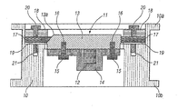
- JP-A-10 259877 which is less susceptible to leakage and which comprises component parts which can be replaced without compromising the integrity of the valve, the valve being characterised in that the mounting plate is fixed to the rear surface of the disc element by bolts which extend through apertures in the mounting plate into blind internally threaded bores formed in the rear surface of the disc element.
- the disc element of the valve member can easily be removed as a complete unit and replaced. In this manner the need for a removable seal on the valve member is avoided, thereby reducing the number of potential leak paths compared with known butterfly valves. Also, the fixing of the mounting plate to the disc element does not create a potential leak path.
- valve members of known butterfly valves are mounted in position by passing the turning axle through a bore which extends through the body of the valve member.
- the valve member is then fixed to the axle by inserting a pin radially into the axle through an aperture in the valve member.
- a disadvantage of this arrangement is that the torque required to turn the valve member against the flow of fluid in a pipeline can be substantial with the result that the pin could break.
- the axle comprises a portion intermediate its opposite ends, which is non-circular in section, the disc element and mounting plate of the valve member together defining a through-passage having a complementary cross-sectional shape to the axle.
- the valve member is unable to rotate about the axle and the need for a pin is avoided.
- axle portion and the passageway are square or rectangular in cross section.
- the passageway comprises a channel which extends across the mounting plate and/or across a surface of the disc element.
- the disc element comprises a front surface, a rear surface and a frusto-conical side surface portion which tapers inwardly from the rear surface to the front surface.
- the annular valve seat is detachable from the valve body, the valve seat preferably being secured to the valve body by bolts or other fastenings.
- the internal surface of the tubular valve body 10 is formed with a forwardly-facing annular shoulder.
- An annular valve seat 17 is clamped between the shoulder and a clamping ring 18 by bolts 20, which extend through aligned apertures in the clamping ring 18 and valve seats 17 into blind internally threaded bores 21 that extend axially rearwardly of the valve body 10.
- An annular gasket 19 is disposed between the shoulder of the valve body 10 and the valve seat 17.
- the valve seat 17 comprises an inwardly-facing frusto-conical surface, which is positioned such that when the valve member 11 is closed, the respective frusto-conical surfaces of the valve member 11 and valve seat 17 seal against each other in a fluid tight manner.
- the triple offset arrangement of the valve ensures that the respective frusto-conical surfaces of the valve member 11 and the valve seat 17 solely contact each other when the valve member reaches its fully closed position. This arrangement ensures that the frusto-conical surfaces do not rub against each other, thereby avoiding wear.
- valve member 11 can be removed from the valve body 10 without the need to withdraw the shaft 12. Accordingly, the present invention provides a butterfly valve which is relatively simple and inexpensive in construction, yet provides a reliable seal when the valve is closed which is not susceptible to leakage. Furthermore, the valve is relatively straightforward to repair and maintain.
Landscapes
- Engineering & Computer Science (AREA)
- General Engineering & Computer Science (AREA)
- Mechanical Engineering (AREA)
- Chemical & Material Sciences (AREA)
- Combustion & Propulsion (AREA)
- Lift Valve (AREA)
- Compressor (AREA)
- External Artificial Organs (AREA)
Claims (10)
- Klappenventil, umfassend einen Ventilkörper (10), der eine Ventilöffnung definiert, und ein Ventilbauteil (11), das drehbar in der Ventilöffnung angebracht ist, wobei das Ventilbauteil (11) ein Scheibenelement (13) aufweist, lösbar angebracht an einer Montageplatte (14), wobei das Ventilbauteil (11) an einer drehbaren Achse (12) angebracht ist, die sich zwischen dem Scheibenelement (13) und der Montageplatte (14) erstreckt, wobei der Ventilkörper (10) einen ringförmigen Ventilsitz (17) aufweist, gegen den das Scheibenelement (13) des Ventilbauteils (11) abdichtet, wenn das Ventil geschlossen ist, dadurch gekennzeichnet, dass die Montageplatte (14) an der hinteren Fläche des Scheibenelements (13) durch Bolzen (15) fixiert ist, die sich durch Öffnungen in der Montageplatte (14) in Blindbohrungen (16) mit Innengewinde erstrecken, die in der hinteren Fläche des Scheibenelements (13) gebildet sind.
- Klappenventil nach Anspruch 1, dadurch gekennzeichnet, dass die Achse (12) einen Abschnitt zwischen ihren entgegengesetzten Enden aufweist, der im Querschnitt nicht-kreisförmig ist, wobei das Scheibenelement (13) und die Montageplatte (14) des Ventilbauteils (11) zusammen einen Durchgang definieren, der eine komplementäre Querschnittform zur Achse (12) aufweist.
- Klappenventil nach Anspruch 2, dadurch gekennzeichnet, dass der Abschnitt der Achse (12) und der Durchgang einen quadratischen oder rechteckigen Querschnitt aufweisen.
- Klappenventil nach Anspruch 2 oder 3, worin der Durchgang einen Kanal aufweist, der sich über die Montageplatte (14) und/oder über die Fläche des Scheibenelements (13) erstreckt.
- Klappenventil nach irgendeinem der vorhergehenden Ansprüche, dadurch gekennzeichnet, dass das Scheibenelement (13) eine vordere Fläche, eine hintere Fläche und einen kegelstumpfförmigen konischen Seitenoberflächenabschnitt (13a), der sich von der rückwärtigen Fläche zur vorderen Fläche nach Innen verjüngt, aufweist.
- Klappenventil nach irgendeinem der vorhergehenden Ansprüche, dadurch gekennzeichnet, dass die vordere und die hintere Fläche des Scheibenelements (13) eben und parallel sind.
- Klappenventil nach irgendeinem der vorhergehenden Ansprüche, dadurch gekennzeichnet, dass der ringförmige Ventilsitz (17) vom Ventilkörper (10) lösbar ist.
- Klappenventil nach Anspruch 7, dadurch gekennzeichnet, dass der Ventilsitz (17) durch Befestigungselemente (20) am Ventilkörper (10) gesichert ist
- Klappenventil nach Anspruch 5, dadurch gekennzeichnet, dass der ringförmige Ventilsitz (17) eine kegelstumpfförmige konische Fläche aufweist zum Eingriff in die komplementäre Oberfläche (13a) des Scheibenelements (13).
- Klappenventil nach irgendeinem der vorhergehenden Ansprüche, dadurch gekennzeichnet, dass der ringförmige Ventilsitz (17) eine laminare Konstruktion aus Metall- und Graphitmaterialien umfasst.
Applications Claiming Priority (2)
| Application Number | Priority Date | Filing Date | Title |
|---|---|---|---|
| GBGB0606105.5A GB0606105D0 (en) | 2006-03-28 | 2006-03-28 | Butterfly valve |
| PCT/GB2007/050152 WO2007110664A1 (en) | 2006-03-28 | 2007-03-26 | Butterfly valve |
Publications (2)
| Publication Number | Publication Date |
|---|---|
| EP2059697A1 EP2059697A1 (de) | 2009-05-20 |
| EP2059697B1 true EP2059697B1 (de) | 2010-08-04 |
Family
ID=36384262
Family Applications (1)
| Application Number | Title | Priority Date | Filing Date |
|---|---|---|---|
| EP07733575A Active EP2059697B1 (de) | 2006-03-28 | 2007-03-26 | Klappenventil |
Country Status (7)
| Country | Link |
|---|---|
| US (1) | US8348235B2 (de) |
| EP (1) | EP2059697B1 (de) |
| AT (1) | ATE476617T1 (de) |
| DE (1) | DE602007008260D1 (de) |
| ES (1) | ES2349078T3 (de) |
| GB (1) | GB0606105D0 (de) |
| WO (1) | WO2007110664A1 (de) |
Families Citing this family (13)
| Publication number | Priority date | Publication date | Assignee | Title |
|---|---|---|---|---|
| DE102007050077A1 (de) * | 2007-10-19 | 2009-04-23 | EBRO Armaturen Gebr. Bröer GmbH | Vorrichtung zur Abgabe von fließfähigem oder schüttfähigem Gut |
| US8857792B2 (en) * | 2012-05-14 | 2014-10-14 | Fisher Controls International Llc | Seal ring assemblies for use with rotary valves |
| US9273789B2 (en) | 2013-08-30 | 2016-03-01 | Enviro Valve (US) Inc. | Triple offset butterfly pressure relief valve |
| JP6370705B2 (ja) * | 2014-12-26 | 2018-08-08 | 日立Geニュークリア・エナジー株式会社 | バタフライ弁 |
| US10234039B2 (en) | 2017-05-18 | 2019-03-19 | Dresser, Llc | Arranging butterfly valves for positive sealing of a valve assembly |
| CN107289143A (zh) * | 2017-08-20 | 2017-10-24 | 浙江贝尔控制阀门有限公司 | 一种大口径高温高压全金属密封蝶阀 |
| US11391379B2 (en) | 2019-03-29 | 2022-07-19 | Velan Inc. | Butterfly valve and butterfly disc |
| US11953113B2 (en) | 2020-02-14 | 2024-04-09 | Crane Chempharma & Energy Corp. | Valve with unobstructed flow path having increased flow coefficient |
| US11946557B2 (en) | 2020-02-14 | 2024-04-02 | Crane Chempharma & Energy Corp. | Valve with unobstructed flow path having increased flow coefficient |
| US11841089B2 (en) * | 2020-02-14 | 2023-12-12 | Crane Chempharma & Energy Corp. | Valve with unobstructed flow path having increased flow coefficient |
| US11519509B2 (en) | 2020-02-14 | 2022-12-06 | Crane Chempharma & Energy Corp. | Valve with unobstructed flow path having increased flow coefficient |
| CA3153760A1 (en) | 2021-03-26 | 2022-09-26 | Dezurik, Inc. | High-performance butterfly valve |
| US20250369518A1 (en) * | 2022-05-24 | 2025-12-04 | Pierburg Gmbh | Flap device for an internal combustion engine |
Family Cites Families (16)
| Publication number | Priority date | Publication date | Assignee | Title |
|---|---|---|---|---|
| US1248926A (en) * | 1917-04-06 | 1917-12-04 | Abraham J Schantz | Valve for organ-bellows. |
| US1682075A (en) * | 1925-12-09 | 1928-08-28 | Pelton Water Wheel Co | Water-tight seat for butterfly valves |
| CH435894A (de) * | 1965-03-23 | 1967-05-15 | Adams Karl | Klappenventil mit schrägliegendem Dichtring und exzentrischer Welle |
| FR1543451A (fr) | 1967-09-14 | 1968-10-25 | Ct De Rech S De Pont A Mousson | Vanne papillon perfectionnée |
| US3905577A (en) * | 1973-03-08 | 1975-09-16 | Anchor Darling Valve Co | Valve |
| GB2031119B (en) * | 1978-09-19 | 1983-01-12 | Solent & Pratt | Butterfly valve |
| US4428395A (en) * | 1980-03-11 | 1984-01-31 | Bravo Sergio M | Lock apparatus for storage tanks |
| US4944489A (en) * | 1989-08-10 | 1990-07-31 | Gebruder Adams Armaturen U. Apparate Gmbh & Co., K.G. | Rotary valve and seal |
| US5377954A (en) * | 1993-12-06 | 1995-01-03 | Adams Gmbh & Co. Armaturen Kg | Valve with seal ring having edge-welded laminations |
| US5564679A (en) * | 1994-07-15 | 1996-10-15 | Mks Instruments, Inc. | Chemically-resistant fluid control valves |
| US6079695A (en) * | 1995-10-12 | 2000-06-27 | Orbit Valve Company | Butterfly valve construction |
| US5707040A (en) * | 1995-10-12 | 1998-01-13 | Orbit Valve Company | Replaceable seal members for butterfly valve |
| US5934647A (en) * | 1996-10-23 | 1999-08-10 | Adams Gmbh & Co. Armaturen Kg | Metal seal for valve |
| JP4084861B2 (ja) | 1997-03-19 | 2008-04-30 | アドバンスド エナジー ジャパン株式会社 | ヒータを具えた制御弁 |
| US6367771B1 (en) * | 1997-07-10 | 2002-04-09 | Lucien Mazot | Butterfly valve with offset bearings |
| US7264221B2 (en) * | 2005-09-19 | 2007-09-04 | Yeary & Associates, Inc. | Butterfly valve assembly with improved flow characteristics |
-
2006
- 2006-03-28 GB GBGB0606105.5A patent/GB0606105D0/en not_active Ceased
-
2007
- 2007-03-26 ES ES07733575T patent/ES2349078T3/es active Active
- 2007-03-26 WO PCT/GB2007/050152 patent/WO2007110664A1/en not_active Ceased
- 2007-03-26 EP EP07733575A patent/EP2059697B1/de active Active
- 2007-03-26 US US12/295,156 patent/US8348235B2/en active Active
- 2007-03-26 AT AT07733575T patent/ATE476617T1/de not_active IP Right Cessation
- 2007-03-26 DE DE602007008260T patent/DE602007008260D1/de active Active
Also Published As
| Publication number | Publication date |
|---|---|
| ES2349078T3 (es) | 2010-12-27 |
| WO2007110664A1 (en) | 2007-10-04 |
| US8348235B2 (en) | 2013-01-08 |
| US20090114869A1 (en) | 2009-05-07 |
| GB0606105D0 (en) | 2006-05-03 |
| ATE476617T1 (de) | 2010-08-15 |
| DE602007008260D1 (de) | 2010-09-16 |
| EP2059697A1 (de) | 2009-05-20 |
Similar Documents
| Publication | Publication Date | Title |
|---|---|---|
| EP2059697B1 (de) | Klappenventil | |
| CN103026109B (zh) | 阀组件和阀组件的使用方法 | |
| JP5457838B2 (ja) | チューブ端バタフライ流量調節及び閉止バルブ | |
| CN101889161B (zh) | 对准关闭件和阀杆的装置和方法 | |
| NO340207B1 (no) | Kuleventiltetning med dynamisk c-tetning og statisk c-tetning | |
| US9976666B1 (en) | Butterfly valve assembly | |
| US11384846B2 (en) | Top entry ball valve and method | |
| CN212839517U (zh) | 流动控制阀及用于流动控制阀的密封垫圈 | |
| CN107532728B (zh) | 可调节耳轴阀和相关方法 | |
| US4512363A (en) | Slide valve | |
| US8727316B1 (en) | Knife gate valve with urethane liner | |
| US11143312B2 (en) | Eccentric rotary valve | |
| US11885437B2 (en) | Stem seal cartridge for valve | |
| US10408355B2 (en) | Pressure activated valve seat | |
| KR101402915B1 (ko) | 밸브 부재 및 이를 이용한 버터플라이 밸브 | |
| GB2472200A (en) | Ball valve | |
| US5947157A (en) | Throttling device and element | |
| US20070023727A1 (en) | Butterfly valve | |
| CA2543718A1 (en) | Completely separable bolted knife gate valve body assembly with removable wear components | |
| EP0769113B1 (de) | Ventil | |
| JPH1151211A (ja) | ボールバルブ | |
| KR102122754B1 (ko) | 메인샤프트와 디스크의 이격이 방지되는 버터플라이 밸브 | |
| DE102009012611B3 (de) | Dichtungen für dreifach oder vierfach asymmetrisch aufgebaute Absperrklappen | |
| KR200235793Y1 (ko) | 몸통 고무 코팅 버터플라이 밸브 | |
| US20200256395A1 (en) | Adapter for a valve system |
Legal Events
| Date | Code | Title | Description |
|---|---|---|---|
| PUAI | Public reference made under article 153(3) epc to a published international application that has entered the european phase |
Free format text: ORIGINAL CODE: 0009012 |
|
| 17P | Request for examination filed |
Effective date: 20090213 |
|
| AK | Designated contracting states |
Kind code of ref document: A1 Designated state(s): AT BE BG CH CY CZ DE DK EE ES FI FR GB GR HU IE IS IT LI LT LU LV MC MT NL PL PT RO SE SI SK TR |
|
| AX | Request for extension of the european patent |
Extension state: AL BA HR MK RS |
|
| 17Q | First examination report despatched |
Effective date: 20090625 |
|
| GRAP | Despatch of communication of intention to grant a patent |
Free format text: ORIGINAL CODE: EPIDOSNIGR1 |
|
| DAX | Request for extension of the european patent (deleted) | ||
| GRAS | Grant fee paid |
Free format text: ORIGINAL CODE: EPIDOSNIGR3 |
|
| GRAA | (expected) grant |
Free format text: ORIGINAL CODE: 0009210 |
|
| AK | Designated contracting states |
Kind code of ref document: B1 Designated state(s): AT BE BG CH CY CZ DE DK EE ES FI FR GB GR HU IE IS IT LI LT LU LV MC MT NL PL PT RO SE SI SK TR |
|
| REG | Reference to a national code |
Ref country code: GB Ref legal event code: FG4D |
|
| REG | Reference to a national code |
Ref country code: CH Ref legal event code: EP |
|
| REG | Reference to a national code |
Ref country code: IE Ref legal event code: FG4D |
|
| REF | Corresponds to: |
Ref document number: 602007008260 Country of ref document: DE Date of ref document: 20100916 Kind code of ref document: P |
|
| REG | Reference to a national code |
Ref country code: NL Ref legal event code: VDEP Effective date: 20100804 |
|
| REG | Reference to a national code |
Ref country code: ES Ref legal event code: FG2A Effective date: 20101214 |
|
| LTIE | Lt: invalidation of european patent or patent extension |
Effective date: 20100804 |
|
| PG25 | Lapsed in a contracting state [announced via postgrant information from national office to epo] |
Ref country code: LT Free format text: LAPSE BECAUSE OF FAILURE TO SUBMIT A TRANSLATION OF THE DESCRIPTION OR TO PAY THE FEE WITHIN THE PRESCRIBED TIME-LIMIT Effective date: 20100804 Ref country code: AT Free format text: LAPSE BECAUSE OF FAILURE TO SUBMIT A TRANSLATION OF THE DESCRIPTION OR TO PAY THE FEE WITHIN THE PRESCRIBED TIME-LIMIT Effective date: 20100804 Ref country code: FI Free format text: LAPSE BECAUSE OF FAILURE TO SUBMIT A TRANSLATION OF THE DESCRIPTION OR TO PAY THE FEE WITHIN THE PRESCRIBED TIME-LIMIT Effective date: 20100804 Ref country code: NL Free format text: LAPSE BECAUSE OF FAILURE TO SUBMIT A TRANSLATION OF THE DESCRIPTION OR TO PAY THE FEE WITHIN THE PRESCRIBED TIME-LIMIT Effective date: 20100804 |
|
| PG25 | Lapsed in a contracting state [announced via postgrant information from national office to epo] |
Ref country code: CY Free format text: LAPSE BECAUSE OF FAILURE TO SUBMIT A TRANSLATION OF THE DESCRIPTION OR TO PAY THE FEE WITHIN THE PRESCRIBED TIME-LIMIT Effective date: 20100804 Ref country code: BG Free format text: LAPSE BECAUSE OF FAILURE TO SUBMIT A TRANSLATION OF THE DESCRIPTION OR TO PAY THE FEE WITHIN THE PRESCRIBED TIME-LIMIT Effective date: 20101104 Ref country code: PL Free format text: LAPSE BECAUSE OF FAILURE TO SUBMIT A TRANSLATION OF THE DESCRIPTION OR TO PAY THE FEE WITHIN THE PRESCRIBED TIME-LIMIT Effective date: 20100804 Ref country code: PT Free format text: LAPSE BECAUSE OF FAILURE TO SUBMIT A TRANSLATION OF THE DESCRIPTION OR TO PAY THE FEE WITHIN THE PRESCRIBED TIME-LIMIT Effective date: 20101206 Ref country code: SI Free format text: LAPSE BECAUSE OF FAILURE TO SUBMIT A TRANSLATION OF THE DESCRIPTION OR TO PAY THE FEE WITHIN THE PRESCRIBED TIME-LIMIT Effective date: 20100804 Ref country code: IS Free format text: LAPSE BECAUSE OF FAILURE TO SUBMIT A TRANSLATION OF THE DESCRIPTION OR TO PAY THE FEE WITHIN THE PRESCRIBED TIME-LIMIT Effective date: 20101204 |
|
| PG25 | Lapsed in a contracting state [announced via postgrant information from national office to epo] |
Ref country code: GR Free format text: LAPSE BECAUSE OF FAILURE TO SUBMIT A TRANSLATION OF THE DESCRIPTION OR TO PAY THE FEE WITHIN THE PRESCRIBED TIME-LIMIT Effective date: 20101105 Ref country code: LV Free format text: LAPSE BECAUSE OF FAILURE TO SUBMIT A TRANSLATION OF THE DESCRIPTION OR TO PAY THE FEE WITHIN THE PRESCRIBED TIME-LIMIT Effective date: 20100804 Ref country code: BE Free format text: LAPSE BECAUSE OF FAILURE TO SUBMIT A TRANSLATION OF THE DESCRIPTION OR TO PAY THE FEE WITHIN THE PRESCRIBED TIME-LIMIT Effective date: 20100804 Ref country code: SE Free format text: LAPSE BECAUSE OF FAILURE TO SUBMIT A TRANSLATION OF THE DESCRIPTION OR TO PAY THE FEE WITHIN THE PRESCRIBED TIME-LIMIT Effective date: 20100804 |
|
| PG25 | Lapsed in a contracting state [announced via postgrant information from national office to epo] |
Ref country code: DK Free format text: LAPSE BECAUSE OF FAILURE TO SUBMIT A TRANSLATION OF THE DESCRIPTION OR TO PAY THE FEE WITHIN THE PRESCRIBED TIME-LIMIT Effective date: 20100804 |
|
| PG25 | Lapsed in a contracting state [announced via postgrant information from national office to epo] |
Ref country code: EE Free format text: LAPSE BECAUSE OF FAILURE TO SUBMIT A TRANSLATION OF THE DESCRIPTION OR TO PAY THE FEE WITHIN THE PRESCRIBED TIME-LIMIT Effective date: 20100804 Ref country code: RO Free format text: LAPSE BECAUSE OF FAILURE TO SUBMIT A TRANSLATION OF THE DESCRIPTION OR TO PAY THE FEE WITHIN THE PRESCRIBED TIME-LIMIT Effective date: 20100804 Ref country code: SK Free format text: LAPSE BECAUSE OF FAILURE TO SUBMIT A TRANSLATION OF THE DESCRIPTION OR TO PAY THE FEE WITHIN THE PRESCRIBED TIME-LIMIT Effective date: 20100804 Ref country code: CZ Free format text: LAPSE BECAUSE OF FAILURE TO SUBMIT A TRANSLATION OF THE DESCRIPTION OR TO PAY THE FEE WITHIN THE PRESCRIBED TIME-LIMIT Effective date: 20100804 |
|
| PLBE | No opposition filed within time limit |
Free format text: ORIGINAL CODE: 0009261 |
|
| STAA | Information on the status of an ep patent application or granted ep patent |
Free format text: STATUS: NO OPPOSITION FILED WITHIN TIME LIMIT |
|
| 26N | No opposition filed |
Effective date: 20110506 |
|
| REG | Reference to a national code |
Ref country code: DE Ref legal event code: R097 Ref document number: 602007008260 Country of ref document: DE Effective date: 20110506 |
|
| PG25 | Lapsed in a contracting state [announced via postgrant information from national office to epo] |
Ref country code: MC Free format text: LAPSE BECAUSE OF NON-PAYMENT OF DUE FEES Effective date: 20110331 |
|
| REG | Reference to a national code |
Ref country code: CH Ref legal event code: PL |
|
| PG25 | Lapsed in a contracting state [announced via postgrant information from national office to epo] |
Ref country code: MT Free format text: LAPSE BECAUSE OF FAILURE TO SUBMIT A TRANSLATION OF THE DESCRIPTION OR TO PAY THE FEE WITHIN THE PRESCRIBED TIME-LIMIT Effective date: 20100804 |
|
| PG25 | Lapsed in a contracting state [announced via postgrant information from national office to epo] |
Ref country code: CH Free format text: LAPSE BECAUSE OF NON-PAYMENT OF DUE FEES Effective date: 20110331 Ref country code: LI Free format text: LAPSE BECAUSE OF NON-PAYMENT OF DUE FEES Effective date: 20110331 |
|
| PG25 | Lapsed in a contracting state [announced via postgrant information from national office to epo] |
Ref country code: LU Free format text: LAPSE BECAUSE OF NON-PAYMENT OF DUE FEES Effective date: 20110326 |
|
| PG25 | Lapsed in a contracting state [announced via postgrant information from national office to epo] |
Ref country code: TR Free format text: LAPSE BECAUSE OF FAILURE TO SUBMIT A TRANSLATION OF THE DESCRIPTION OR TO PAY THE FEE WITHIN THE PRESCRIBED TIME-LIMIT Effective date: 20100804 |
|
| PG25 | Lapsed in a contracting state [announced via postgrant information from national office to epo] |
Ref country code: HU Free format text: LAPSE BECAUSE OF FAILURE TO SUBMIT A TRANSLATION OF THE DESCRIPTION OR TO PAY THE FEE WITHIN THE PRESCRIBED TIME-LIMIT Effective date: 20100804 |
|
| REG | Reference to a national code |
Ref country code: FR Ref legal event code: PLFP Year of fee payment: 10 |
|
| REG | Reference to a national code |
Ref country code: FR Ref legal event code: PLFP Year of fee payment: 11 |
|
| REG | Reference to a national code |
Ref country code: GB Ref legal event code: 732E Free format text: REGISTERED BETWEEN 20170622 AND 20170628 |
|
| REG | Reference to a national code |
Ref country code: FR Ref legal event code: PLFP Year of fee payment: 12 |
|
| PGFP | Annual fee paid to national office [announced via postgrant information from national office to epo] |
Ref country code: ES Payment date: 20250402 Year of fee payment: 19 |
|
| PGFP | Annual fee paid to national office [announced via postgrant information from national office to epo] |
Ref country code: GB Payment date: 20260220 Year of fee payment: 20 |
|
| PGFP | Annual fee paid to national office [announced via postgrant information from national office to epo] |
Ref country code: DE Payment date: 20260219 Year of fee payment: 20 Ref country code: IE Payment date: 20260223 Year of fee payment: 20 |
|
| PGFP | Annual fee paid to national office [announced via postgrant information from national office to epo] |
Ref country code: IT Payment date: 20260219 Year of fee payment: 20 |
|
| PGFP | Annual fee paid to national office [announced via postgrant information from national office to epo] |
Ref country code: FR Payment date: 20260220 Year of fee payment: 20 |