EP2059935B1 - Disjoncteur à vide - Google Patents
Disjoncteur à vide Download PDFInfo
- Publication number
- EP2059935B1 EP2059935B1 EP07802210A EP07802210A EP2059935B1 EP 2059935 B1 EP2059935 B1 EP 2059935B1 EP 07802210 A EP07802210 A EP 07802210A EP 07802210 A EP07802210 A EP 07802210A EP 2059935 B1 EP2059935 B1 EP 2059935B1
- Authority
- EP
- European Patent Office
- Prior art keywords
- contact
- vacuum switch
- ring
- vacuum
- switch according
- Prior art date
- Legal status (The legal status is an assumption and is not a legal conclusion. Google has not performed a legal analysis and makes no representation as to the accuracy of the status listed.)
- Not-in-force
Links
Images


Classifications
-
- H—ELECTRICITY
- H01—ELECTRIC ELEMENTS
- H01H—ELECTRIC SWITCHES; RELAYS; SELECTORS; EMERGENCY PROTECTIVE DEVICES
- H01H33/00—High-tension or heavy-current switches with arc-extinguishing or arc-preventing means
- H01H33/60—Switches wherein the means for extinguishing or preventing the arc do not include separate means for obtaining or increasing flow of arc-extinguishing fluid
- H01H33/66—Vacuum switches
- H01H33/664—Contacts; Arc-extinguishing means, e.g. arcing rings
-
- H—ELECTRICITY
- H01—ELECTRIC ELEMENTS
- H01H—ELECTRIC SWITCHES; RELAYS; SELECTORS; EMERGENCY PROTECTIVE DEVICES
- H01H1/00—Contacts
- H01H1/50—Means for increasing contact pressure, preventing vibration of contacts, holding contacts together after engagement, or biasing contacts to the open position
-
- H—ELECTRICITY
- H01—ELECTRIC ELEMENTS
- H01H—ELECTRIC SWITCHES; RELAYS; SELECTORS; EMERGENCY PROTECTIVE DEVICES
- H01H33/00—High-tension or heavy-current switches with arc-extinguishing or arc-preventing means
- H01H33/60—Switches wherein the means for extinguishing or preventing the arc do not include separate means for obtaining or increasing flow of arc-extinguishing fluid
- H01H33/66—Vacuum switches
- H01H33/662—Housings or protective screens
-
- H—ELECTRICITY
- H01—ELECTRIC ELEMENTS
- H01H—ELECTRIC SWITCHES; RELAYS; SELECTORS; EMERGENCY PROTECTIVE DEVICES
- H01H33/00—High-tension or heavy-current switches with arc-extinguishing or arc-preventing means
- H01H33/60—Switches wherein the means for extinguishing or preventing the arc do not include separate means for obtaining or increasing flow of arc-extinguishing fluid
- H01H33/66—Vacuum switches
- H01H33/666—Operating arrangements
-
- H—ELECTRICITY
- H01—ELECTRIC ELEMENTS
- H01H—ELECTRIC SWITCHES; RELAYS; SELECTORS; EMERGENCY PROTECTIVE DEVICES
- H01H1/00—Contacts
- H01H1/58—Electric connections to or between contacts; Terminals
- H01H1/5822—Flexible connections between movable contact and terminal
-
- H—ELECTRICITY
- H01—ELECTRIC ELEMENTS
- H01H—ELECTRIC SWITCHES; RELAYS; SELECTORS; EMERGENCY PROTECTIVE DEVICES
- H01H1/00—Contacts
- H01H1/58—Electric connections to or between contacts; Terminals
- H01H1/5822—Flexible connections between movable contact and terminal
- H01H2001/5827—Laminated connections, i.e. the flexible conductor is composed of a plurality of thin flexible conducting layers
-
- H—ELECTRICITY
- H01—ELECTRIC ELEMENTS
- H01H—ELECTRIC SWITCHES; RELAYS; SELECTORS; EMERGENCY PROTECTIVE DEVICES
- H01H33/00—High-tension or heavy-current switches with arc-extinguishing or arc-preventing means
- H01H33/60—Switches wherein the means for extinguishing or preventing the arc do not include separate means for obtaining or increasing flow of arc-extinguishing fluid
- H01H33/66—Vacuum switches
- H01H33/664—Contacts; Arc-extinguishing means, e.g. arcing rings
- H01H2033/6648—Contacts containing flexible parts, e.g. to improve contact pressure
-
- H—ELECTRICITY
- H01—ELECTRIC ELEMENTS
- H01H—ELECTRIC SWITCHES; RELAYS; SELECTORS; EMERGENCY PROTECTIVE DEVICES
- H01H33/00—High-tension or heavy-current switches with arc-extinguishing or arc-preventing means
- H01H33/60—Switches wherein the means for extinguishing or preventing the arc do not include separate means for obtaining or increasing flow of arc-extinguishing fluid
- H01H33/66—Vacuum switches
- H01H33/6606—Terminal arrangements
Definitions
- the invention is directed to a vacuum switch, in particular vacuum circuit breaker, for medium and high voltage with a movable switching unit disposed within a vacuum switching chamber, which movably comprises a contact tappet, an insulator and a driving or switching rod inserted into the vacuum interrupter chamber through a metal bellows, and a fixed contact inserted into the housing of the vacuum interrupter chamber, wherein the upper end of the insulator is fixedly connected to the contact plunger and the lower end of the insulator to the drive or shift rod, and wherein the contact plunger has a conductive connection to a conductor which is in current-conducting Connection with at least one laterally arranged outgoing contact is.
- Circuit-breakers offer the possibility of dissolving existing electrical connections, whereby electrical currents of up to 160 kA can be switched. These currents occur, for example, when there is a short circuit or a ground fault in high voltage networks. Circuit-breakers can not only switch normal operating currents and low overload currents, just like switch-disconnectors, but also separate high overload currents and maximum short-circuit currents. As an overcurrent protection device with a very high switching capacity in the range of 80 kA - 160 kA, you can switch operating equipment or system components both undisturbed and for a limited time in a faulty state, eg in the event of a short circuit. Types of circuit breaker are in addition to gas pressure switches and circuit breakers vacuum switch. With vacuum switches, the contacts are under vacuum to avoid an arc.
- a gas-insulated switchgear with vacuum switches is known in which are arranged within a filled with insulating gas vessel of the gas-insulated switchgear designed as a vacuum switch circuit breaker.
- a vacuum switch each comprises a vacuum switching chamber, which is designed as a vacuum space.
- a fixed contact plunger and a movable contact plunger are arranged, which are led out with their respective contact rods from the vacuum space of the vacuum interrupter chamber.
- the contact rod of the movable contact plunger is led out by a bellows from the vacuum space or the vacuum interrupter chamber.
- this plunger communicates with a power supply carrier and an actuator is provided for actuating the selector rod of the movable contact plunger.
- the insulating capacity of such vacuum switch must not only ensure the necessary insulating capacity of the switching and isolating distance, but also ensure that leakage or surface currents in the open state of the separation path does not flow from the upper port of the vacuum interrupter chamber to the lower port, the connected power supply carrier. To ensure this, it is necessary to have corresponding distances between the connections and the arrangement of the vacuum switch within a vessel filled with insulating gas. This leads to large types of vacuum switches and thus equipped switchgear.
- the movable in the longitudinal direction switching contact of the contact plunger is moved at the startup at high speed and then bounces on the switching contact of the fixed contact and repeatedly hits with a frequency corresponding to the drive system and the movable mass.
- This impact causes during the operating times of the vacuum switch on the one hand, mechanical stress, which strain the metal bellows through which the movable contact plunger is led out of the vacuum chamber.
- a disadvantage of this embodiment is that either a further housing must be provided within the vacuum interrupter chamber, in which the conductive connection is arranged protected, resulting in a significantly increased assembly costs, or it is a complex structure of the conductive connection is necessary that must be formed alternately to a conductive layer an adhesion prevention layer.
- the invention is based on the object to provide a solution that provides a simplified, less expensive and improved embodiment of a flexible, conductive connection to the outgoing contact.
- this object is achieved in that the inner cross-sectional area of the vacuum interrupter chamber at the level of the outgoing contact around the contact plunger around by foil or plate-like design, electrically conductive cover, the layer or layer are arranged one above the other and each cover at least partially, is covered nationwide.
- foil- or plate-like, conductive cover elements preferably made of metal foil or metal plates, are provided which cover the inner cross-sectional area of the vacuum interrupter chamber around the contact plunger around the area, they are in each pestle, ie each shift in particular evenly moved relative to each other without relative displacement ,
- the arranged on the contact plunger material region is moved directly from the contact plunger, whereas the opposite, preferably fixed to a ring area of the cover this movement does not follow.
- the layers are not merely slid against each other, but are spaced and moved apart from each other at a distance from each other.
- the cover elements at least partially form the conductive connection, wherein then continue the conductor as arranged around the contact plunger ring or Ring section is formed.
- the flexible, conductive connection can if desired be formed limited to a circle segment section. But it is also possible to form the entire formed between the contact plunger and an annular conductor circular ring as a conductive connection.
- a particularly flexible embodiment which is resistant to adhesions can be achieved in that the conductive connection is constructed flexibly from a plurality of connecting elements comprising flexible cover elements comprising a plurality of rotationally offset elements around the axis formed by the contact plunger.
- a particularly preferred arrangement of the cover is therefore in an advantageous embodiment, when the flexible connecting elements each cover at least a partial surface of at least one cover at least a partial surface of a cover of a neighboring in the direction of rotation connecting element.
- the entire formed between the contact plunger and the outgoing contact annular cross-sectional area of the vacuum chamber interior can then completely cover that the connecting elements with their mutually overlapping faces in their entirety, the cross-sectional area of the vacuum interrupter chamber and / or Cover the conductor within the ring and / or a circular ring formed between the contact plunger and the ring.
- the cover elements and / or connecting elements are arranged one above the other in layers or layers, with the helical superimposition of covering elements and / or connecting elements being particularly preferred.
- the flexibility and freedom of movement of the connecting elements can be advantageously supported according to the invention in that the connecting elements comprise an outer ring and an inner ring and at least one outer and inner ring connecting and preferably a cover member forming support member. It can further be provided that the respective outer ring of the connecting elements is fixed in the ring of the conductor and that the respective inner ring of the connecting elements is enclosed in a plunger ring, in which case the plunger ring is arranged on the contact plunger.
- a component which comprises in itself flexibly one above the other several layers of covering elements having connecting elements which are arranged on the one hand on the ring, which is in contact with the outgoing contact and which on the other hand are fixed and arranged on the ram ring, which directly adjusts the Movement of the contact plunger transfers.
- the tappet ring then directly follows the tappet movement together with the inner ring of the connecting elements, whereas the outer ring is retained in the ring of the conductor. This movement is supported by the shape of the support elements, which form a mechanical connection between diametrically opposite areas of the outer ring of the connecting elements in the manner of a bow-like rising bridge.
- the inventive design of the conductive connection between the contact plunger and the annular conductor or the ring of the conductor by in top view (or below) of individual overlapping over and / or juxtaposed cover a visually dense surface formed in supervision , which covers the inner cross-sectional area of the vacuum chamber at the level of the outgoing contact.
- This optically dense area also serves to prevent charged particles from falling from the top, i. E., During operation of the vacuum switch. Move above the conductor located switching area between fixed and movable contact down to the metallic bellows and to the guided therein drive rod.
- the inventive flexible, conductive connection securely transmits the flow of current from the movable contact plunger through the ring to the output contact. It is sufficiently stable, so that in particular the current flow to the output contact and the flow of current from the contact plunger to the conductive connection is ensured, on the other hand, but also the movement of the Contact plunger is followed.
- the conductive compound is still permeable to air, so that an evacuation of the vacuum chamber is possible, on the other hand, it closes off the lower part of the vacuum chamber such that the resulting by the arc occurring metallic Abbrand do not hit the insulator arranged in the vacuum chamber, there condense and so can form a conductive layer.
- the conductor or the conductive connection of individual segments that is formed from the connecting elements with cover elements of thin and flexible conductive metal so that the length of each segment or connecting element, ie the radial extent of each Connecting element, at least the largest possible radial distance between the outer fixed connection point of the segment in the form of the outer ring and the connection point on the movable contact plunger in the form of the inner ring corresponds.
- the individual connecting elements in the longitudinal axis of the vacuum chamber are spaced apart and kept separate, whereby the air permeability between the connecting elements with their covering and thus the Evakuierein the vacuum chamber is made possible and ensured.
- the connecting elements are then further offset from one another such that the cross-sectional area of the vacuum chamber, seen from above or below from the longitudinal axis of the vacuum chamber, is optically completely filled.
- the displacement of the connecting elements relative to one another can take place in spiral form, spiral staircase form, in zigzag form or other arrangements, as long as it is ensured in each case that the entire inner cross-sectional area of the vacuum chamber is covered.
- the outer ring of the conductor is fixedly arranged on the inside of the vacuum chamber on a contact ring arranged between two ceramic bodies of the vacuum chamber, where it is in contact with the outgoing contact.
- the opposite inner side of the connecting elements is fixedly arranged on the tappet ring and above fixed to the movable contact plunger.
- This consists of an upper gas-tight ceramic cylinder 2 and a lower gas-tight ceramic cylinder 3.
- the upper ceramic cylinder 2 is closed by a connection cover 4.
- a contact ring 5 is formed between upper ceramic cylinder 2 and lower ceramic cylinder 3.
- the contact ring 5 has outgoing contacts 6, via which a ring 7 of a conductor 8 with a load conductor 9 is in electrically conductive connection.
- a drive or shift rod 11 is vacuum-tight in the interior of the vacuum interrupter chamber 1 introduced.
- the interior thus forms a vacuum chamber 12, in which a high vacuum of 10 -7 to 10 -9 Torr or 10 -7 to 10 -9 mbar is formed.
- a high vacuum of 10 -7 to 10 -9 Torr or 10 -7 to 10 -9 mbar is formed.
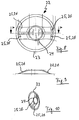
- the finished mounted vacuum interrupter chamber 1 of the vacuum switch with a cast resin jacket 13 or a cast resin housing surrounded, as is made Fig. 2 is apparent.
- FIG. 3 is a schematic sectional view of the vacuum chamber 12 of the vacuum interrupter chamber 1 in the closed position of switching contact pieces 14a, 14b, ie an electrically conductive connection from a not shown generation line conductor 15 by a fixed contact 16 and a movable contact plunger 17 and the conductor 8 and the outgoing contact 6 through the vacuum chamber 12 through to the load conductor 9.
- an isolating distance is not formed.
- the switch contact pieces 14a, 14b move apart so far that between them a distance is formed, which then forms a separation distance.
- the illustrated vacuum switch is a vacuum switch for medium and high voltage.
- a movable switching unit is formed within the vacuum interrupter chamber 1, which comprises the lower switching contact piece 14b, the fixed thereto contact plunger 17, the fixed thereto insulator 18 and the drive or shift rod 11.
- a flexible, electrically conductive connection 20 with a conductor 8 or for the formation of a conductor 8 is arranged at the level of the outgoing contacts 6 or of the contact ring 5 or current connection carrier on the contact plunger 17.
- This conductive connection 20 of the electric current flow to the load conductor 9 is made, so that there is a current-conducting connection to at least one of the outgoing contacts 6.
- the conductor 8 comprises a ring 7, which is arranged fixed on the inside of the contact ring 5. Furthermore, the conductor 8 comprises a plunger ring 21, which is arranged with its inner surface, preferably stationary, on the outer circumference of the contact plunger 17. The plunger ring 21 and the ring 7 are connected to each other via a plurality of connecting elements 22.
- a single connecting element 22 is shown in plan view in FIG. It consists of an outer ring 23 and an inner ring 24 and four support members 25 connecting the outer ring 23 and the inner ring 24, wherein the outer ring 23, the inner ring 24 and the support members 25 of an electrically conductive, foil-like or plate-like Material exist.
- the support members 25 form the support members 25 from the outer ring 23 to the inner ring 24 toward rising cover 26, so that they span the interior of the outer ring 23 from one side to the diametrically opposite side arcuately with the involvement of the inner ring 24.
- Fig. 4 is a view in the direction of the longitudinal axis 27 of the contact plunger 17 in plan view from above, are clamped between the plunger ring 21 and the ring 7 a plurality of connecting elements 22, 22 ', 22 ", 22"' one above the other in the direction of the axis 27 arranged.
- the respectively superimposed connection element 22, 22 ', 22 ", 22"' respectively offset in the direction of rotation about the axis 27 by 10-15 degrees to each other, so that all these connecting elements 22 in total with their respective cover elements 26, 26 ' or support elements 25, 25 'overall cover the area formed between the ring 7 and the plunger ring 21 annular surface area-covering.
- connection elements 22 thus form the flexible part of the conductive connection 20 and, together with the ring 7 and the plunger ring 21, the conductor as a whole 8 off. How out Fig.
- the connecting elements 22 with their outer ring 23 each fixed in the ring 7 and with its inner ring 24 fixedly arranged in the tappet ring 21, wherein between the respective superposed individual connecting elements 22, a distance in the longitudinal axial direction is present, so that through the Connecting elements 22 with their cover elements 26 and support members 25 through an air or gas space connection is continuous, on the other hand but in supervision according to Fig. 4 an opaque cover is provided by these connecting elements 22.
- the closed position of the switching contact pieces 14a, 14b already corresponds to and in Fig. 3 illustrated positioning of the connecting elements 22 with the off Fig. 6 apparent concave underside and the out Fig. 7 apparent convex trained top.
- the cover elements 26 and the support elements 25 are designed so flexible that they accompany the movement of the contact plunger 17 in the individual switching operations from the closed switching position to the open disconnect position and back again.
- Each switch contact piece 14a, 14b has a two-part contact and button 28, which comprises an annular outer switching and contact surface 29 and a circular inner switching and contact surface 30.
- the outer switching and contact surface 29 is fixed in position on a carrier body 31 of the respective switching contact piece 14a, 14b arranged and the inner switching and contact surface 30 is arranged relative to the outer switching and contact surface 29 movable on support heads 32.
- springs 33 are arranged with its one end on a base surface 36, wherein abut with its other end to a stop ring 35 of the inner plunger 34.
- the in Fig. 13 shown retracted position of the inner switching and contact surface 30 are the switching and contact surfaces 29, 30 of the upper switching contact piece 14a and lower switching contact piece 14b flat to each other, so that a flat contact and button 28 is formed. In this position, the springs 33 are placed over the stopper ring 35 in its compressed position.
- the outer switching and contact surfaces 29 of the upper and lower switching contact pieces 14a, 14b move away from each other.
- the inner switching and contact surfaces 30 of the upper and lower switching contact piece 14a, 14b remain but initially in flat succession, as long as the driving force of the now relaxing springs 33 is sufficient to push the plunger 34 into the in FIG. 14 illustrated extended position of inner switching and contact surface 30 to move. If now the contact plunger 17 further away from the fixed contact 16, remove the inner switching and contact surfaces 30 of the lower and upper switching contact piece 14a, 14b from each other, so that now the separation distance is formed.
- the outer switching and contact surfaces 29 are made of an annular material which is highly conductive. This material is suitable for transferring the nominal current which is to be conducted by the vacuum switch in each case with very little resistance.
- the underlying springs 33 are made of so convenientlytragherem material, such as a copper-tungsten alloy.
- the material of the outer switching and contact surfaces 29 is in particular oxygen-free and consists for example of a copper-silver alloy.
- the material of the inner switching and contact surface 30 consists for example of a copper-chromium alloy.
- the inner switching and contact surfaces 30 are on support heads 32, which are part of a spiral arrangement of contacts for supporting the inner switching and contact surface 30. This makes it possible to generate an axial magnetic field with which larger and stronger arcs can be configured as diffuse arcs.
- the inner plunger 34 consists of a configuration of web-like segments 37 on which the support heads 32 are arranged spirally aligned with each other, wherein the support heads 32 are formed and connected electrically conductive.
- the insulator 18 is one made of ceramic material.
- the enclosure of the vacuum interrupter chamber 1 preferably consists of a cast resin jacket or cast resin housing made of a silicone material or silicone casting resin.
- the life and the life cycle of a vacuum interrupter chamber is increased by the combination of various measures, the overall insulation behavior of the vacuum chamber 12 and the vacuum interrupter 1 improved and thus achieved a compact design of the vacuum interrupter chamber 1 and thus a vacuum switch total, with the sake of completeness listed again be that the upper ceramic cylinder 2 and the lower ceramic cylinder 3 made of a gas-tight ceramic material, otherwise a vacuum in the vacuum chamber 12 would not be upright.
- this may still be arranged in a case of a switchgear filled with insulating gas, if desired.
Landscapes
- High-Tension Arc-Extinguishing Switches Without Spraying Means (AREA)
- Contacts (AREA)
- Arc-Extinguishing Devices That Are Switches (AREA)
- Gas-Insulated Switchgears (AREA)
- Switches Operated By Changes In Physical Conditions (AREA)
Claims (14)
- Interrupteur à vide, en particulier disjoncteur à vide, pour moyenne et haute tension, comportant une unité de commutation mobile disposée à l'intérieur d'une chambre de commutation à vide (1), ladite unité de commutation mobile comprenant, disposés de façon mobile les uns par rapport aux autres, un poussoir de contact (17), un isolateur (18) et une tige d'entraînement ou de commutation (11) introduite dans la chambre de commutation à vide (1) au moyen d'un soufflet métallique (10), ainsi qu'un contact fixe (16) inséré dans le boîtier de la chambre de commutation à vide (1), où l'extrémité supérieure de l'isolateur (18) est fixement raccordée au poussoir de contact (17) et l'extrémité inférieure de l'isolateur (18) est fixement raccordée à la tige d'entraînement ou de commutation (11), et où le poussoir de contact (17) présente une connexion flexible électriquement conductrice (20) avec un conducteur (8) se trouvant en connexion conductrice de courant avec au moins un contact de sortie (6) disposé latéralement,
caractérisé en ce
qu'au niveau du ou des contacts de sortie (6), tout autour du poussoir de contact (17), la surface de section intérieure de la chambre de commutation à vide (1) est intégralement recouverte par des éléments de couverture (26) électriquement conducteurs disposés contre celui-ci sous forme de feuilles ou de plaquettes, lesquels sont superposés par strates ou par couches et se recouvrent au moins en partie. - Interrupteur à vide selon la revendication 1, caractérisé en ce que les éléments de couverture (26) forment la connexion conductrice (20) au moins en partie.
- Interrupteur à vide selon la revendication 1 ou la revendication 2, caractérisé en ce que le conducteur (8) est réalisé comme bague (7) ou partie de bague disposée tout autour du poussoir de contact (17).
- Interrupteur à vide selon l'une des revendications précédentes, caractérisé en ce que la connexion conductrice (20) est constituée de manière flexible par plusieurs éléments de connexion (22) comprenant des éléments de couverture (26) flexibles et disposés en décalage l'un par rapport à l'autre en direction de rotation autour de l'axe (27) formé par le poussoir de contact (17).
- Interrupteur à vide selon la revendication 4, caractérisé en ce que les éléments de connexion (22) flexibles recouvrent chacun par une surface partielle d'au moins un élément de couverture (26) au moins une surface partielle d'un élément de couverture (26) d'un élément de connexion (22) contigu en direction de rotation.
- Interrupteur à vide selon la revendication 4 ou la revendication 5, caractérisé en ce que, par leurs surfaces partielles qui se recouvrent réciproquement, les éléments de connexion (22) recouvrent dans sa totalité la surface de section de la chambre de commutation à vide (1) et/ou du conducteur (8) à l'intérieur de la bague (7) et/ou d'une bague circulaire formée entre le poussoir de contact (17) et la bague (7).
- Interrupteur à vide selon l'une des revendications précédentes, caractérisé en ce que des éléments de couverture (26) et/ou des éléments de connexion (22) sont superposés par strates ou par couches.
- Interrupteur à vide selon l'une des revendications précédentes, caractérisé en ce que les éléments de couverture (26) et/ou les éléments de connexion (22) sont hélicoïdalement superposés.
- Interrupteur à vide selon l'une des revendications précédentes, caractérisé en ce que les éléments de connexion (22) comprennent une bague extérieure (23) et une bague intérieure (24) ainsi qu'au moins un élément d'appui (25) reliant la bague extérieure (23) et la bague intérieure (24) et formant de préférence un élément de couverture (26).
- Interrupteur à vide selon l'une des revendications précédentes, caractérisé en ce que la bague extérieure (23) des éléments de connexion (22) est fixée dans la bague (7) du conducteur (8).
- Interrupteur à vide selon l'une des revendications précédentes, caractérisé en ce que la bague intérieure (24) des éléments de connexion (22) est sertie dans une bague de poussoir (21).
- Interrupteur à vide selon l'une des revendications précédentes, caractérisé en ce que la bague de poussoir (21) est disposée sur le poussoir de contact (17).
- Interrupteur à vide selon l'une des revendications précédentes, caractérisé en ce que le cylindre en céramique supérieur (2), le cylindre en céramique inférieur (3) et l'isolateur (18) sont en céramique imperméable aux gaz.
- Interrupteur à vide selon l'une des revendications précédentes, caractérisé en ce que l'interrupteur à vide est logé dans un boîtier extérieur en résine moulée (13).
Applications Claiming Priority (2)
| Application Number | Priority Date | Filing Date | Title |
|---|---|---|---|
| DE102006042101A DE102006042101B4 (de) | 2006-09-07 | 2006-09-07 | Vakuumschalter für Mittel- und Hochspannungen |
| PCT/EP2007/007827 WO2008028676A1 (fr) | 2006-09-07 | 2007-09-07 | Disjoncteur à vide |
Publications (2)
| Publication Number | Publication Date |
|---|---|
| EP2059935A1 EP2059935A1 (fr) | 2009-05-20 |
| EP2059935B1 true EP2059935B1 (fr) | 2010-11-17 |
Family
ID=38830413
Family Applications (2)
| Application Number | Title | Priority Date | Filing Date |
|---|---|---|---|
| EP07818074A Not-in-force EP2059938B1 (fr) | 2006-09-07 | 2007-09-07 | Disjoncteur à vide |
| EP07802210A Not-in-force EP2059935B1 (fr) | 2006-09-07 | 2007-09-07 | Disjoncteur à vide |
Family Applications Before (1)
| Application Number | Title | Priority Date | Filing Date |
|---|---|---|---|
| EP07818074A Not-in-force EP2059938B1 (fr) | 2006-09-07 | 2007-09-07 | Disjoncteur à vide |
Country Status (10)
| Country | Link |
|---|---|
| US (2) | US8110769B2 (fr) |
| EP (2) | EP2059938B1 (fr) |
| JP (2) | JP2010503162A (fr) |
| KR (3) | KR100887414B1 (fr) |
| CN (3) | CN101140837A (fr) |
| AT (2) | ATE488853T1 (fr) |
| BR (2) | BRPI0714750A2 (fr) |
| DE (3) | DE102006042101B4 (fr) |
| MX (2) | MX2009002545A (fr) |
| WO (2) | WO2008028672A1 (fr) |
Families Citing this family (35)
| Publication number | Priority date | Publication date | Assignee | Title |
|---|---|---|---|---|
| US8248760B2 (en) * | 2010-07-07 | 2012-08-21 | Eaton Corporation | Switch arrangement for an electrical switchgear |
| EP2434513B1 (fr) * | 2010-09-24 | 2019-04-17 | ABB Schweiz AG | Interrupteur sous vide pour agencement de disjoncteur |
| DE102011101856A1 (de) * | 2011-01-21 | 2012-07-26 | Abb Technology Ag | Kontaktsystem für Stromleiter |
| JP5789999B2 (ja) * | 2011-01-31 | 2015-10-07 | セイコーエプソン株式会社 | 液体噴射装置 |
| US9472356B2 (en) * | 2011-06-02 | 2016-10-18 | Mitsubishi Electric Corporation | Tank-type vacuum circuit breaker |
| EP2551871A1 (fr) * | 2011-07-29 | 2013-01-30 | ABB Technology AG | Disque à contact à bande tressée |
| US9335378B2 (en) * | 2011-12-13 | 2016-05-10 | Finley Lee Ledbetter | Flexible magnetic field coil for measuring ionic quantity |
| EP3754684A1 (fr) * | 2012-06-11 | 2020-12-23 | ABB Schweiz AG | Interrupteur à vide doté d'un agencement de contact coaxial double de chaque côté |
| CN103871775B (zh) * | 2012-12-14 | 2016-05-11 | 伊顿公司 | 真空灭弧室和具有真空灭弧室的真空断路器 |
| US9761394B2 (en) | 2013-02-08 | 2017-09-12 | Hubbell Incorporated | Current interrupter for high voltage switches |
| CN103337406A (zh) * | 2013-06-17 | 2013-10-02 | 北海银河产业投资股份有限公司 | 真空灭弧室软连接 |
| CN103762116B (zh) * | 2014-01-20 | 2016-06-22 | 浙江紫光电器有限公司 | 一种高压真空灭弧室的触头 |
| CN103956305B (zh) * | 2014-04-11 | 2017-02-08 | 江苏大正电气有限公司 | 一种用于智能控制与保护装置的动触头连接板 |
| GB2527800A (en) * | 2014-07-02 | 2016-01-06 | Eaton Ind Netherlands Bv | Circuit breaker |
| KR102245184B1 (ko) * | 2014-11-21 | 2021-04-27 | 삼성전자주식회사 | 안테나를 갖는 전자 장치 |
| WO2016171047A1 (fr) * | 2015-04-23 | 2016-10-27 | 株式会社日立製作所 | Appareillage de connexion |
| FR3037709B1 (fr) * | 2015-06-22 | 2018-05-11 | Schneider Electric Industries Sas | Ampoule a vide et appareillage de protection electrique comportant une telle ampoule |
| CN105374615B (zh) * | 2015-12-09 | 2017-07-11 | 中国西电电气股份有限公司 | 一种高压大电流的选相合闸装置 |
| US10284696B2 (en) * | 2016-09-08 | 2019-05-07 | Guangdong Oppo Mobile Telecommunications Corp., Ltd. | Shell, method for manufacturing the same and mobile terminal having the same |
| CN107170637A (zh) * | 2017-07-04 | 2017-09-15 | 合肥东玖电气有限公司 | 一种真空断路器 |
| DE102017214607A1 (de) * | 2017-08-22 | 2019-02-28 | Siemens Aktiengesellschaft | Lagereinrichtung zum Lagern eines Bewegkontakts an einem elektrischen Bauelement für einen Leistungsschalter, Leistungsschalter und Schaltanlage |
| CN108511261B (zh) * | 2018-03-27 | 2019-08-23 | 西安交通大学 | 一种基于一体化电极结构的直流断路器及其使用方法 |
| CN108914123A (zh) * | 2018-07-27 | 2018-11-30 | 苏州瑞沁精密机械有限公司 | 一种金属零件表面防腐蚀处理方法 |
| CN109637249B (zh) * | 2019-01-14 | 2021-10-01 | 上海中侨职业技术学院 | 一种空气流量计传感器故障模拟检测接头及其使用方法 |
| CA3137902A1 (fr) | 2019-04-26 | 2020-10-29 | G & W Electric Company | Appareillage de commutation avec ensemble de declenchement manuel et verrouillage mecanique |
| MX2021013025A (es) | 2019-04-26 | 2022-03-11 | G & W Electric | Conmutadores con material dielectrico sobremoldeado. |
| US12266490B2 (en) | 2019-04-26 | 2025-04-01 | G & W Electric Company | Modular recloser |
| WO2020219916A1 (fr) * | 2019-04-26 | 2020-10-29 | G & W Electric Company | Ensemble appareillage de commutation intégré |
| US12112906B2 (en) | 2019-04-26 | 2024-10-08 | G & W Electric Company | Integrated switchgear assembly |
| KR102716098B1 (ko) * | 2019-06-13 | 2024-10-15 | 에이치디현대일렉트릭 주식회사 | 가스 절연 차단기 |
| US11545321B2 (en) | 2020-03-31 | 2023-01-03 | Hubbell Incorporated | System and method for operating an electrical switch |
| CN111564334A (zh) * | 2020-05-09 | 2020-08-21 | 云南电网有限责任公司电力科学研究院 | 一种真空灭弧室触头装置 |
| US11694864B2 (en) * | 2020-09-30 | 2023-07-04 | Eaton Intelligent Power Limited | Vacuum interrupter with trap for running cathode tracks |
| US12183523B2 (en) * | 2021-10-07 | 2024-12-31 | S&C Electric Company | Insulated drive vacuum interrupter |
| CN118538569B (zh) * | 2024-07-24 | 2024-12-03 | 宇邦电气有限公司 | 一种全包覆式三工位真空断路器 |
Family Cites Families (27)
| Publication number | Priority date | Publication date | Assignee | Title |
|---|---|---|---|---|
| US3239635A (en) * | 1964-11-17 | 1966-03-08 | Baude John | Disc shaped arcing contact structure producing predetermined arc blowout characteristic |
| CH474832A (de) * | 1968-09-11 | 1969-06-30 | Bbc Brown Boveri & Cie | Vakuumschalter |
| US4153827A (en) | 1976-01-26 | 1979-05-08 | Merlin Gerin | Magnetic blow-out arc extinguishing device |
| FR2339243A1 (fr) * | 1976-01-26 | 1977-08-19 | Merlin Gerin | Conducteur de connexion flexible |
| US4384179A (en) * | 1981-02-12 | 1983-05-17 | Westinghouse Electric Corp. | Stiff flexible connector for a circuit breaker or other electrical apparatus |
| DE3112776C2 (de) * | 1981-03-31 | 1986-05-22 | Wickmann-Werke Böblingen GmbH, 7030 Böblingen | Mittelspannungs-Schaltvorrichtung mit einem Vakuum-Unterbrecher zwischen einer Sammelschiene und einem Kabelanschlußstutzen |
| GB8819166D0 (en) * | 1988-08-12 | 1988-09-14 | Ass Elect Ind | Magnetic actuator & permanent magnet |
| DE4021945C2 (de) | 1990-07-10 | 1999-12-30 | Alstom Sachsenwerk Gmbh | Schaltvorrichtung zur Unterbrechung von Fehlerströmen |
| US5294761A (en) * | 1991-11-11 | 1994-03-15 | Kabushiki Kaisha Toshiba | Vacuum interrupter |
| DE4329349A1 (de) | 1993-08-27 | 1995-03-02 | Siemens Ag | Gasdicht gekapseltes Schaltteil |
| US5387772A (en) * | 1993-11-01 | 1995-02-07 | Cooper Industries, Inc. | Vacuum switch |
| DE4405206A1 (de) | 1994-02-18 | 1995-08-24 | Abb Research Ltd | Schaltvorrichtung |
| DE4419380C1 (de) * | 1994-05-30 | 1995-10-19 | Siemens Ag | Leistungsschaltermodul |
| DE19505370C2 (de) * | 1995-02-17 | 2000-11-02 | Abb Patent Gmbh | Vakuumschalter |
| US5530216A (en) * | 1995-03-07 | 1996-06-25 | Eaton Corporation | Flexible connector for a circuit breaker |
| DE19712182A1 (de) * | 1997-03-22 | 1998-09-24 | Abb Patent Gmbh | Vakuumkammer |
| JP3778686B2 (ja) | 1998-03-26 | 2006-05-24 | 三菱電機株式会社 | 可撓性導体 |
| SG87815A1 (en) | 1998-03-26 | 2002-04-16 | Mitsubishi Electric Corp | Flexible conductor and switchgear made with thereof |
| WO2000021107A1 (fr) * | 1998-10-02 | 2000-04-13 | Hitachi, Ltd. | Interrupteur a vide et commutateur a vide utilisant l'interrupteur a vide |
| KR100370934B1 (ko) | 1999-04-01 | 2003-02-05 | 미쓰비시덴키 가부시키가이샤 | 스위치 기어 및 전력 개폐기 |
| JP3788148B2 (ja) * | 1999-12-16 | 2006-06-21 | 株式会社日立製作所 | 真空スイッチ及びその運転方法 |
| US6444939B1 (en) * | 2000-05-09 | 2002-09-03 | Eaton Corporation | Vacuum switch operating mechanism including laminated flexible shunt connector |
| JP4494673B2 (ja) * | 2001-07-12 | 2010-06-30 | 三菱電機株式会社 | 電力用開閉装置 |
| RU2249874C2 (ru) * | 2003-03-26 | 2005-04-10 | Общество С Ограниченной Ответственностью "Промышленная Группа Тэл Таврида Электрик" | Вакуумный выключатель |
| JP4394963B2 (ja) | 2004-01-08 | 2010-01-06 | 三菱電機株式会社 | スイッチギヤ |
| JP2005197128A (ja) | 2004-01-08 | 2005-07-21 | Mitsubishi Electric Corp | 複合絶縁スイッチギヤ |
| US7906742B2 (en) * | 2004-07-05 | 2011-03-15 | Abb Research Ltd. | Vacuum interrupter chamber and contact arrangement for a vacuum circuit breaker |
-
2006
- 2006-09-07 DE DE102006042101A patent/DE102006042101B4/de not_active Expired - Fee Related
-
2007
- 2007-01-31 CN CNA2007100031298A patent/CN101140837A/zh active Pending
- 2007-03-02 KR KR1020070021059A patent/KR100887414B1/ko not_active Expired - Fee Related
- 2007-09-07 JP JP2009527063A patent/JP2010503162A/ja active Pending
- 2007-09-07 EP EP07818074A patent/EP2059938B1/fr not_active Not-in-force
- 2007-09-07 KR KR1020097005367A patent/KR20090075664A/ko not_active Withdrawn
- 2007-09-07 MX MX2009002545A patent/MX2009002545A/es active IP Right Grant
- 2007-09-07 BR BRPI0714750-3A patent/BRPI0714750A2/pt not_active IP Right Cessation
- 2007-09-07 JP JP2009527062A patent/JP2010503161A/ja active Pending
- 2007-09-07 AT AT07818074T patent/ATE488853T1/de active
- 2007-09-07 MX MX2009002546A patent/MX2009002546A/es active IP Right Grant
- 2007-09-07 CN CNA2007800333811A patent/CN101523537A/zh active Pending
- 2007-09-07 WO PCT/EP2007/007821 patent/WO2008028672A1/fr not_active Ceased
- 2007-09-07 BR BRPI0714749-0A patent/BRPI0714749A2/pt not_active IP Right Cessation
- 2007-09-07 EP EP07802210A patent/EP2059935B1/fr not_active Not-in-force
- 2007-09-07 WO PCT/EP2007/007827 patent/WO2008028676A1/fr not_active Ceased
- 2007-09-07 CN CN2007800333328A patent/CN101617377B/zh not_active Expired - Fee Related
- 2007-09-07 DE DE502007005700T patent/DE502007005700D1/de active Active
- 2007-09-07 KR KR1020097005368A patent/KR20090075665A/ko not_active Ceased
- 2007-09-07 AT AT07802210T patent/ATE488848T1/de active
- 2007-09-07 US US12/440,383 patent/US8110769B2/en not_active Expired - Fee Related
- 2007-09-07 DE DE502007005699T patent/DE502007005699D1/de active Active
- 2007-09-07 US US12/440,392 patent/US8198562B2/en not_active Expired - Fee Related
Also Published As
| Publication number | Publication date |
|---|---|
| JP2010503162A (ja) | 2010-01-28 |
| ATE488853T1 (de) | 2010-12-15 |
| WO2008028672A1 (fr) | 2008-03-13 |
| BRPI0714750A2 (pt) | 2013-05-14 |
| CN101617377A (zh) | 2009-12-30 |
| US8198562B2 (en) | 2012-06-12 |
| KR100887414B1 (ko) | 2009-03-06 |
| DE102006042101B4 (de) | 2008-09-25 |
| CN101140837A (zh) | 2008-03-12 |
| US20100000972A1 (en) | 2010-01-07 |
| DE502007005699D1 (de) | 2010-12-30 |
| KR20090075665A (ko) | 2009-07-08 |
| WO2008028672A8 (fr) | 2009-05-07 |
| CN101523537A (zh) | 2009-09-02 |
| US8110769B2 (en) | 2012-02-07 |
| BRPI0714749A2 (pt) | 2013-05-14 |
| JP2010503161A (ja) | 2010-01-28 |
| WO2008028676A8 (fr) | 2009-07-02 |
| WO2008028676A1 (fr) | 2008-03-13 |
| KR20080023091A (ko) | 2008-03-12 |
| MX2009002545A (es) | 2009-06-01 |
| DE502007005700D1 (de) | 2010-12-30 |
| EP2059938A1 (fr) | 2009-05-20 |
| EP2059938B1 (fr) | 2010-11-17 |
| KR20090075664A (ko) | 2009-07-08 |
| US20100025375A1 (en) | 2010-02-04 |
| CN101617377B (zh) | 2013-03-06 |
| DE102006042101A1 (de) | 2008-03-27 |
| MX2009002546A (es) | 2009-06-01 |
| ATE488848T1 (de) | 2010-12-15 |
| EP2059935A1 (fr) | 2009-05-20 |
Similar Documents
| Publication | Publication Date | Title |
|---|---|---|
| EP2059935B1 (fr) | Disjoncteur à vide | |
| EP2702597B1 (fr) | Coupe-circuit de surtension | |
| DD226690A1 (de) | Schalterpol | |
| EP0800191B1 (fr) | Disjoncteur | |
| DE69117399T2 (de) | Gaslastschalter | |
| EP0435865A1 (fr) | Sectionneur a coupure en charge contenant un tube commutateur a vide et procede de fonctionnement dudit sectionneur a coupure en charge. | |
| DE102007004950B4 (de) | Elektrische Schaltanlage | |
| EP0822565B1 (fr) | Disjoncteur électrique à gaz comprimé | |
| DE8314797U1 (de) | Vakuumschalter mit Doppelunterbrechung | |
| EP1899999B1 (fr) | Appareil de commutation electrique | |
| EP1881510B1 (fr) | Tube interrupteur à vide | |
| DE2048506B2 (de) | Vakuumschalter | |
| WO2000052719A1 (fr) | Chambre d'interruption sous vide dotee d'un isolateur annulaire | |
| EP3453044B1 (fr) | Commutateur à double contact comportant des chambres de coupure sous vide | |
| EP3559967B1 (fr) | Appareillage de commutation électrique | |
| WO2024083488A1 (fr) | Module de base pour dispositifs de commutation à haute tension avec interrupteurs à vide, et dispositif de commutation à haute tension comprenant le module de base | |
| DE3786141T2 (de) | Vakuumschalter. | |
| EP0222073A2 (fr) | Pôle d'interrupteur pour disjoncteur de puissance | |
| EP4341976A1 (fr) | Interrupteur à vide et agencement comprenant des interrupteurs à vide, et procédé pour éteindre des interrupteurs à vide | |
| DE102011006013B3 (de) | Vakuumschaltröhre und Schalterpol | |
| EP3698387A1 (fr) | Dispositif et procédé pour la commutation de hautes tensions comprenant un dispositif de commutation et exactement une pile résistive | |
| EP3959734A1 (fr) | Commutateur électrique | |
| DE3803066A1 (de) | Vakuumschaltroehre | |
| WO2021170330A1 (fr) | Moyen de commande électrique et procédé de commutation d'un moyen de commande électrique | |
| DE10200956A1 (de) | Hochspannungs-Leistungsschalter |
Legal Events
| Date | Code | Title | Description |
|---|---|---|---|
| PUAI | Public reference made under article 153(3) epc to a published international application that has entered the european phase |
Free format text: ORIGINAL CODE: 0009012 |
|
| 17P | Request for examination filed |
Effective date: 20090225 |
|
| AK | Designated contracting states |
Kind code of ref document: A1 Designated state(s): AT BE BG CH CY CZ DE DK EE ES FI FR GB GR HU IE IS IT LI LT LU LV MC MT NL PL PT RO SE SI SK TR |
|
| AX | Request for extension of the european patent |
Extension state: AL BA HR MK RS |
|
| GRAP | Despatch of communication of intention to grant a patent |
Free format text: ORIGINAL CODE: EPIDOSNIGR1 |
|
| DAX | Request for extension of the european patent (deleted) | ||
| GRAS | Grant fee paid |
Free format text: ORIGINAL CODE: EPIDOSNIGR3 |
|
| GRAA | (expected) grant |
Free format text: ORIGINAL CODE: 0009210 |
|
| AK | Designated contracting states |
Kind code of ref document: B1 Designated state(s): AT BE BG CH CY CZ DE DK EE ES FI FR GB GR HU IE IS IT LI LT LU LV MC MT NL PL PT RO SE SI SK TR |
|
| REG | Reference to a national code |
Ref country code: GB Ref legal event code: FG4D Free format text: NOT ENGLISH |
|
| REG | Reference to a national code |
Ref country code: CH Ref legal event code: EP |
|
| REG | Reference to a national code |
Ref country code: IE Ref legal event code: FG4D |
|
| REF | Corresponds to: |
Ref document number: 502007005699 Country of ref document: DE Date of ref document: 20101230 Kind code of ref document: P |
|
| REG | Reference to a national code |
Ref country code: NL Ref legal event code: VDEP Effective date: 20101117 |
|
| LTIE | Lt: invalidation of european patent or patent extension |
Effective date: 20101117 |
|
| PG25 | Lapsed in a contracting state [announced via postgrant information from national office to epo] |
Ref country code: LT Free format text: LAPSE BECAUSE OF FAILURE TO SUBMIT A TRANSLATION OF THE DESCRIPTION OR TO PAY THE FEE WITHIN THE PRESCRIBED TIME-LIMIT Effective date: 20101117 |
|
| PG25 | Lapsed in a contracting state [announced via postgrant information from national office to epo] |
Ref country code: LV Free format text: LAPSE BECAUSE OF FAILURE TO SUBMIT A TRANSLATION OF THE DESCRIPTION OR TO PAY THE FEE WITHIN THE PRESCRIBED TIME-LIMIT Effective date: 20101117 Ref country code: SI Free format text: LAPSE BECAUSE OF FAILURE TO SUBMIT A TRANSLATION OF THE DESCRIPTION OR TO PAY THE FEE WITHIN THE PRESCRIBED TIME-LIMIT Effective date: 20101117 Ref country code: BG Free format text: LAPSE BECAUSE OF FAILURE TO SUBMIT A TRANSLATION OF THE DESCRIPTION OR TO PAY THE FEE WITHIN THE PRESCRIBED TIME-LIMIT Effective date: 20110217 Ref country code: FI Free format text: LAPSE BECAUSE OF FAILURE TO SUBMIT A TRANSLATION OF THE DESCRIPTION OR TO PAY THE FEE WITHIN THE PRESCRIBED TIME-LIMIT Effective date: 20101117 Ref country code: PT Free format text: LAPSE BECAUSE OF FAILURE TO SUBMIT A TRANSLATION OF THE DESCRIPTION OR TO PAY THE FEE WITHIN THE PRESCRIBED TIME-LIMIT Effective date: 20110317 Ref country code: SE Free format text: LAPSE BECAUSE OF FAILURE TO SUBMIT A TRANSLATION OF THE DESCRIPTION OR TO PAY THE FEE WITHIN THE PRESCRIBED TIME-LIMIT Effective date: 20101117 Ref country code: IS Free format text: LAPSE BECAUSE OF FAILURE TO SUBMIT A TRANSLATION OF THE DESCRIPTION OR TO PAY THE FEE WITHIN THE PRESCRIBED TIME-LIMIT Effective date: 20110317 Ref country code: CY Free format text: LAPSE BECAUSE OF FAILURE TO SUBMIT A TRANSLATION OF THE DESCRIPTION OR TO PAY THE FEE WITHIN THE PRESCRIBED TIME-LIMIT Effective date: 20101117 Ref country code: NL Free format text: LAPSE BECAUSE OF FAILURE TO SUBMIT A TRANSLATION OF THE DESCRIPTION OR TO PAY THE FEE WITHIN THE PRESCRIBED TIME-LIMIT Effective date: 20101117 |
|
| REG | Reference to a national code |
Ref country code: IE Ref legal event code: FD4D |
|
| PG25 | Lapsed in a contracting state [announced via postgrant information from national office to epo] |
Ref country code: GR Free format text: LAPSE BECAUSE OF FAILURE TO SUBMIT A TRANSLATION OF THE DESCRIPTION OR TO PAY THE FEE WITHIN THE PRESCRIBED TIME-LIMIT Effective date: 20110218 |
|
| PG25 | Lapsed in a contracting state [announced via postgrant information from national office to epo] |
Ref country code: CZ Free format text: LAPSE BECAUSE OF FAILURE TO SUBMIT A TRANSLATION OF THE DESCRIPTION OR TO PAY THE FEE WITHIN THE PRESCRIBED TIME-LIMIT Effective date: 20101117 Ref country code: EE Free format text: LAPSE BECAUSE OF FAILURE TO SUBMIT A TRANSLATION OF THE DESCRIPTION OR TO PAY THE FEE WITHIN THE PRESCRIBED TIME-LIMIT Effective date: 20101117 Ref country code: ES Free format text: LAPSE BECAUSE OF FAILURE TO SUBMIT A TRANSLATION OF THE DESCRIPTION OR TO PAY THE FEE WITHIN THE PRESCRIBED TIME-LIMIT Effective date: 20110228 Ref country code: IE Free format text: LAPSE BECAUSE OF FAILURE TO SUBMIT A TRANSLATION OF THE DESCRIPTION OR TO PAY THE FEE WITHIN THE PRESCRIBED TIME-LIMIT Effective date: 20101117 |
|
| PG25 | Lapsed in a contracting state [announced via postgrant information from national office to epo] |
Ref country code: RO Free format text: LAPSE BECAUSE OF FAILURE TO SUBMIT A TRANSLATION OF THE DESCRIPTION OR TO PAY THE FEE WITHIN THE PRESCRIBED TIME-LIMIT Effective date: 20101117 Ref country code: SK Free format text: LAPSE BECAUSE OF FAILURE TO SUBMIT A TRANSLATION OF THE DESCRIPTION OR TO PAY THE FEE WITHIN THE PRESCRIBED TIME-LIMIT Effective date: 20101117 Ref country code: PL Free format text: LAPSE BECAUSE OF FAILURE TO SUBMIT A TRANSLATION OF THE DESCRIPTION OR TO PAY THE FEE WITHIN THE PRESCRIBED TIME-LIMIT Effective date: 20101117 Ref country code: DK Free format text: LAPSE BECAUSE OF FAILURE TO SUBMIT A TRANSLATION OF THE DESCRIPTION OR TO PAY THE FEE WITHIN THE PRESCRIBED TIME-LIMIT Effective date: 20101117 |
|
| PLBE | No opposition filed within time limit |
Free format text: ORIGINAL CODE: 0009261 |
|
| STAA | Information on the status of an ep patent application or granted ep patent |
Free format text: STATUS: NO OPPOSITION FILED WITHIN TIME LIMIT |
|
| 26N | No opposition filed |
Effective date: 20110818 |
|
| REG | Reference to a national code |
Ref country code: DE Ref legal event code: R097 Ref document number: 502007005699 Country of ref document: DE Effective date: 20110818 |
|
| PG25 | Lapsed in a contracting state [announced via postgrant information from national office to epo] |
Ref country code: IT Free format text: LAPSE BECAUSE OF FAILURE TO SUBMIT A TRANSLATION OF THE DESCRIPTION OR TO PAY THE FEE WITHIN THE PRESCRIBED TIME-LIMIT Effective date: 20101117 |
|
| BERE | Be: lapsed |
Owner name: SWITCHCRAFT EUROPE G.M.B.H. Effective date: 20110930 |
|
| PG25 | Lapsed in a contracting state [announced via postgrant information from national office to epo] |
Ref country code: MC Free format text: LAPSE BECAUSE OF NON-PAYMENT OF DUE FEES Effective date: 20110930 |
|
| REG | Reference to a national code |
Ref country code: CH Ref legal event code: PL |
|
| PG25 | Lapsed in a contracting state [announced via postgrant information from national office to epo] |
Ref country code: BE Free format text: LAPSE BECAUSE OF NON-PAYMENT OF DUE FEES Effective date: 20110930 |
|
| PG25 | Lapsed in a contracting state [announced via postgrant information from national office to epo] |
Ref country code: LI Free format text: LAPSE BECAUSE OF NON-PAYMENT OF DUE FEES Effective date: 20110930 Ref country code: CH Free format text: LAPSE BECAUSE OF NON-PAYMENT OF DUE FEES Effective date: 20110930 |
|
| PGFP | Annual fee paid to national office [announced via postgrant information from national office to epo] |
Ref country code: GB Payment date: 20120920 Year of fee payment: 6 |
|
| PGFP | Annual fee paid to national office [announced via postgrant information from national office to epo] |
Ref country code: DE Payment date: 20121001 Year of fee payment: 6 Ref country code: FR Payment date: 20121008 Year of fee payment: 6 |
|
| PG25 | Lapsed in a contracting state [announced via postgrant information from national office to epo] |
Ref country code: MT Free format text: LAPSE BECAUSE OF FAILURE TO SUBMIT A TRANSLATION OF THE DESCRIPTION OR TO PAY THE FEE WITHIN THE PRESCRIBED TIME-LIMIT Effective date: 20101117 |
|
| PG25 | Lapsed in a contracting state [announced via postgrant information from national office to epo] |
Ref country code: LU Free format text: LAPSE BECAUSE OF NON-PAYMENT OF DUE FEES Effective date: 20110907 |
|
| PG25 | Lapsed in a contracting state [announced via postgrant information from national office to epo] |
Ref country code: TR Free format text: LAPSE BECAUSE OF FAILURE TO SUBMIT A TRANSLATION OF THE DESCRIPTION OR TO PAY THE FEE WITHIN THE PRESCRIBED TIME-LIMIT Effective date: 20101117 |
|
| PG25 | Lapsed in a contracting state [announced via postgrant information from national office to epo] |
Ref country code: HU Free format text: LAPSE BECAUSE OF FAILURE TO SUBMIT A TRANSLATION OF THE DESCRIPTION OR TO PAY THE FEE WITHIN THE PRESCRIBED TIME-LIMIT Effective date: 20101117 |
|
| REG | Reference to a national code |
Ref country code: AT Ref legal event code: MM01 Ref document number: 488848 Country of ref document: AT Kind code of ref document: T Effective date: 20120907 |
|
| PG25 | Lapsed in a contracting state [announced via postgrant information from national office to epo] |
Ref country code: AT Free format text: LAPSE BECAUSE OF NON-PAYMENT OF DUE FEES Effective date: 20120907 |
|
| GBPC | Gb: european patent ceased through non-payment of renewal fee |
Effective date: 20130907 |
|
| REG | Reference to a national code |
Ref country code: DE Ref legal event code: R119 Ref document number: 502007005699 Country of ref document: DE Effective date: 20140401 |
|
| REG | Reference to a national code |
Ref country code: FR Ref legal event code: ST Effective date: 20140530 |
|
| PG25 | Lapsed in a contracting state [announced via postgrant information from national office to epo] |
Ref country code: GB Free format text: LAPSE BECAUSE OF NON-PAYMENT OF DUE FEES Effective date: 20130907 |
|
| PG25 | Lapsed in a contracting state [announced via postgrant information from national office to epo] |
Ref country code: FR Free format text: LAPSE BECAUSE OF NON-PAYMENT OF DUE FEES Effective date: 20130930 Ref country code: DE Free format text: LAPSE BECAUSE OF NON-PAYMENT OF DUE FEES Effective date: 20140401 |