EP2060206A2 - Entraînement pour meuble - Google Patents
Entraînement pour meuble Download PDFInfo
- Publication number
- EP2060206A2 EP2060206A2 EP20080168764 EP08168764A EP2060206A2 EP 2060206 A2 EP2060206 A2 EP 2060206A2 EP 20080168764 EP20080168764 EP 20080168764 EP 08168764 A EP08168764 A EP 08168764A EP 2060206 A2 EP2060206 A2 EP 2060206A2
- Authority
- EP
- European Patent Office
- Prior art keywords
- drive
- furniture
- furniture drive
- electromotive
- drive according
- Prior art date
- Legal status (The legal status is an assumption and is not a legal conclusion. Google has not performed a legal analysis and makes no representation as to the accuracy of the status listed.)
- Withdrawn
Links
Images
Classifications
-
- A—HUMAN NECESSITIES
- A47—FURNITURE; DOMESTIC ARTICLES OR APPLIANCES; COFFEE MILLS; SPICE MILLS; SUCTION CLEANERS IN GENERAL
- A47C—CHAIRS; SOFAS; BEDS
- A47C20/00—Head-, foot- or like rests for beds, sofas or the like
- A47C20/04—Head-, foot- or like rests for beds, sofas or the like with adjustable inclination
- A47C20/041—Head-, foot- or like rests for beds, sofas or the like with adjustable inclination by electric motors
Definitions
- the invention relates to a furniture drive for adjusting at least two movable furniture components of a piece of furniture, which is equipped with a drive direction reversible drive motor.
- the furniture drive in question is generally referred to in the industry as a double drive.
- the main functional parts are each a drive motor, a speed reducer coupled thereto, a fixedly connected to the output member of the Drehierereduziergetriebes spindle and a patch-mounted, secured against rotation spindle nut.
- the spindle nut of each drive unit is operatively connected to a drive member of the furniture component to be adjusted or with a pivot fitting.
- Such a furniture drive is preferably used for adjusting the backrest and the foot part of a slatted frame.
- the invention has for its object to design furniture drives of the type described in more detail so that the number of components is minimized to reduce manufacturing costs, yet the adjustment of at least two movable furniture components is ensured.
- the furniture drive has a single coupled to the drive motor Drehbaumreduziergetriebe with a rotationally driven output member, and that the adjustable furniture components are at least partially in operative connection with an output element of the furniture drive.
- a to be regarded as a double drive furniture drive is created, which is equipped with only one Wheelierereduziergetriebe and preferably with only one output element, whereby the number of these main functional parts is already reduced.
- only a single drive motor is required, so that compared to the versions with two drive motors deleted one of these drive motors. Since the furniture drive is equipped with only one drive motor, the control unit and the handset is simplified accordingly.
- the Drehierereduziergetriebe is a worm drive
- the driven output member is a worm wheel with an internally threaded bore into which a secured against rotation spindle is used, which forms the output element of the furniture drive.
- a slider-shaped sliding element in the form of a push or pressure cap can be placed firmly on at least one end region of the threaded spindle, which is in operative connection with the respective furniture component to be adjusted.
- slider-shaped sliding elements are fixedly mounted on both end regions of the threaded spindle. Each sliding element then forms the output element of the furniture drive.
- threads are resilient, and the spindle can be purchased as a commercial part.
- the threads are in a preferred embodiment either pointed or trapezoidal thread.
- the spindle is moved relative to a lateral end face of the output member of the Drehierereduziergetriebes and thereby actuates the associated, to be adjusted furniture component.
- the spindle is opposite to the two end faces of the output member of the Drehierereduziergetriebes in each position of the furniture component to be adjusted before. It is also provided in a preferred embodiment that are in the lowered positions of the at least two furniture components to be adjusted the output elements of the furniture drive or the end faces of the spindle at equal intervals or approximately equal distances to the lateral end faces of the output member of the Drehierereduziergetriebes or the worm drive.
- the end faces of the output element of the furniture drive or the end faces of the spindle in the lowered position of the at least two furniture components are operatively connected to pivotable drive levers which form the drive members of the at least two furniture components or the drive members of swivel fittings. These levers can be varied by the length of the lever arm necessary for adjusting the furniture components torque. It is also particularly advantageous if the output element of the furniture drive or the spindle spaced in the lowered positions of the at least two furniture components at least one drive lever, as characterized the drive train is virtually no load, while the respective furniture component to be adjusted in the respective end position rests or locked is. The distance may be, for example, 2 mm.
- the output element of the furniture drive or the spindle is associated with at least one limit switch.
- the one or more limit switches may be arranged on a retaining strip, which is either used in at least one housing part or forms an integral molding with this, so that in this at least one limit switch can be used in different positions.
- the design in a preferred embodiment is then chosen so that the limit switches, for example, a front end region of the output element are connected so that the end positions of the opposite furniture component are limited.
- the output elements are designed as spindles which can be driven in rotation, with a spindle at least in sections a right- and the other spindle has at least partially a left-hand thread.
- corresponding spindle nuts are then placed rotationally fixed, which are in operative connection with the drive element of the furniture component to be adjusted or with the pivot fitting.
- the output member of the Drehierereduziergetriebes is formed as a rotational body and coupled to at least one winding drum, and that a plurality of deflection rollers are provided for at least one by means of the winding drum up and unwindable flexible tension element.
- each flexible tension element can be purchased by the meter, and consist in a preferred embodiment of a wire rope.
- the free end of each flexible tension element is fixed to a pivotable about a horizontal axis lever.
- a torque is generated in order to pivot the furniture component or a swivel fitting.
- the free end of each flexible pulling element for pivoting the furniture component or the pivot fitting of another winding drum can be unwound.
- This switch assembly includes limit switch for switching off the motor in the respective end position. Furthermore, at least one further switch can be provided for switching off the motor. The shutdown takes place in one or more between the end positions of the respective furniture component located intermediate positions.
- a further limit switch can be provided to switch off the motor in the lowered positions of the furniture components or the swivel fittings.
- a switch for the basic position is actuated.
- This switch is coupled to the motor circuit or to a control circuit.
- this switch is designed as a so-called opener and opens the circuit, so that no more energy flows to the motor.
- a further contact, for example, a normally open contact of this switch can be actuated, which may also be connected to the controller. Only when the respective hand switch is pressed again, the drive then moves in the desired direction.
- center positions or intermediate positions requires at least one flag, which may for example be in the form of a flip-flop, a bistable electromechanical switch, an electromechanical switch with self-switching or a corresponding controller control.
- the electromotive furniture drive is operated by a manual switch, which has at least two pushbuttons. These two push buttons are the travel keys in the direction of the respective end position of the respective output member or the respective furniture component. If they are held, the drive moves to the next center position or to an intermediate position or to the respective end position.
- a switch is actuated by the traveling drive, whereby the motor is switched off. Only when the previously actuated key is released by releasing and this or another key is pressed again, the drive moves further in the preselected direction until another center position, or an intermediate position or an end position is reached.
- two of the pushbuttons are the travel buttons in the direction of the respective end position. If they are pressed, the drive moves to the next center position or to an intermediate position or to the respective end position.
- Each additional key represents another middle position or an intermediate position. If another key is pressed and held, the drive moves independently of its current position in the direction of the key position assigned to the key and when this is reached, the motor is switched off.
- the furniture drive has two output-side output elements, it can be referred to as a double drive.
- further output elements which may be offset with respect to one another.
- These can be in operative connection with other furniture components, for example with a third or with a fourth furniture component, so that either only one furniture component with the drive train of an electric motor is in operative connection, or on the other hand grouped several furniture components or in an operating sequence at least partially with the Drive train of an electric motor are in operative connection.
- This embodiment of a furniture drive could also be referred to as a multiple drive, but since it has only one electric motor, it could also be referred to as a single drive.
- the output member of the Drehierereduziergetriebes be coupled with two longitudinally of the axis of rotation of the output member of the Drehierereduziergetriebes successively arranged threaded portions having at least partially a co-directional or an opposing thread.
- the threaded sections are rotatably driven by a motor. At least one of the threaded portions could also at least partially form an integral molding with the output member of the Drehierereduziergetriebes.
- the driven by the motor threaded portions may be formed as an internal thread and / or as an external thread.
- the output elements of the furniture drive move in an opposite direction.
- the coupled furniture components also move in an opposite direction, so that, for example, a head and a footboard of a slatted frame moved together or offset up or down.
- the individual threaded sections have different slopes to create different Verstellieri füren or different adjustment paths.
- the drive elements of the furniture drive are designed such that in the basic position of the furniture drive all adjustable furniture components are in the home position, and that starting from this basic position only one connected to the furniture drive furniture component between a basic position and an end position is adjusted.
- the drive elements of the furniture drive are designed such that in the basic position of the furniture drive all adjustable furniture components are in the home position, and that starting from this basic position only one connected to the furniture drive furniture component between a basic position and an end position is adjusted.
- a trained example as slatted furniture according to this embodiment either only the head part between a lowered basic position and a raised position adjusted or it is only the foot part between a lowered basic position and a raised position adjusted.
- all the adjustable furniture components can be adjusted together between a basic position and a raised or displaced position.
- the head and the foot can be adjusted together between a lowered basic position and a raised position.
- all adjustable furniture components can be adjusted in sections together or in sections successively between a basic position and a raised or displaced position.
- a slatted furniture thus only the headboard could first be brought from a basic position in an adjustment, with a certain adjustment additionally a further furniture component, for example, the foot of a slatted frame is moved out of its basic position.
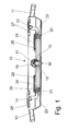
- the Indian FIG. 1 shown furniture drive 10 is a so-called double drive to adjust, for example, the backrest and the footboard of a slatted frame.
- the side rails 11, 12 are shown, which are designed according to another embodiment as a lever fitting and are either fixed or coupled via other levers with the respective furniture component to be adjusted fixed, displaceable or articulated.
- These lateral bars 11, 12 are rotatably mounted on two tubular shafts 13, 14.
- the furniture drive 10 is equipped in the form of a double drive with a single drive motor 15.
- the drive motor 15 is coupled to a Drehierereduziergetriebe 16.
- the Drehierereduziergetriebe 16 is usually a worm drive, wherein the worm 17 is either rotatably mounted on the output pin of the drive motor 15, or the output pin is formed as a worm.
- This worm 17 is in engagement with a worm wheel 18, which is equipped in the illustrated embodiment with a central internal threaded bore.
- the worm wheel 18 forms the output member of the Drehierereduziergetriebes 16.
- the output element of the electromotive furniture drive 10 forming spindle 19 is used. This spindle 19 is secured against rotation.
- the mutually facing surfaces of the end caps 20, 21 and the lever 22, 23 in the lowered position of the side rails 11, 12 also at a distance of, for example, 1 to 2 mm to each other.
- the end portions of the spindle 19 are limit switch strips 24, 25 assigned to turn off the drive motor 15 in the end positions of the side rails 11, 12.
- limit switch bars 24, 25 limit switch 26 can be used optionally in different positions.
- the limit switch strips 24, 25 are integrally formed with at least one housing part of the furniture drive 10.
- the circuit of this limit switch 26 is made so that the inner end switch 26 in the illustration switch the respective spar 11, 12 in the respective upper end position, while the leftmost in the illustration arranged limit switch 26, the motor 15 turns off when the lower end positions of Holms 11, 12 are reached and thereby take the adjustable furniture components their basic positions.
- the housing of the furniture drive 10 is provided with transverse to the spindle 19 movable closers 27, 28. These closers 27, 28 are positively inserted in dovetailed guides.
- the electromotive furniture drive 10 could also be equipped with two spindles, which can be driven by the common drive motor 15.
- a spindle with a right-hand spindle and the other spindle with a left-hand thread would each be provided at least in sections and could be designed as a one-piece molded part with the worm wheel 18. On these spindles could then be placed against rotation secured spindle nuts.
- the output member of the Drehierereduziergetriebes 16 forming worm wheel 18 could also be coupled with one or two winding drums. On each winding drum would be a flexible Tension element wound up and unwound. About a pulley arrangement, the free ends of the flexible tension elements could be connected to the shafts 13, 14. For this purpose, the ends could in turn be attached to levers or on the shafts 13, 14, a further winding shaft would be placed.
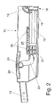
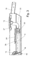
- FIGS. 2 and 3 show the left and right half of the designed as a double drive furniture drive.
- the same components are also provided with the same reference numerals.
Landscapes
- Health & Medical Sciences (AREA)
- General Health & Medical Sciences (AREA)
- Nursing (AREA)
- Power-Operated Mechanisms For Wings (AREA)
- Control Of Electric Motors In General (AREA)
- Connection Of Motors, Electrical Generators, Mechanical Devices, And The Like (AREA)
- Chair Legs, Seat Parts, And Backrests (AREA)
Applications Claiming Priority (1)
| Application Number | Priority Date | Filing Date | Title |
|---|---|---|---|
| DE200720015811 DE202007015811U1 (de) | 2007-11-13 | 2007-11-13 | Möbelantrieb |
Publications (2)
| Publication Number | Publication Date |
|---|---|
| EP2060206A2 true EP2060206A2 (fr) | 2009-05-20 |
| EP2060206A3 EP2060206A3 (fr) | 2014-09-24 |
Family
ID=40394278
Family Applications (1)
| Application Number | Title | Priority Date | Filing Date |
|---|---|---|---|
| EP08168764.2A Withdrawn EP2060206A3 (fr) | 2007-11-13 | 2008-11-10 | Entraînement pour meuble |
Country Status (3)
| Country | Link |
|---|---|
| EP (1) | EP2060206A3 (fr) |
| JP (1) | JP2009119269A (fr) |
| DE (1) | DE202007015811U1 (fr) |
Cited By (1)
| Publication number | Priority date | Publication date | Assignee | Title |
|---|---|---|---|---|
| WO2023099433A1 (fr) * | 2021-12-01 | 2023-06-08 | Hettich Franke Gmbh & Co. Kg | Mécanisme de réglage de hauteur pour une partie de support mobile d'un meuble d'assise, et meuble d'assise |
Families Citing this family (9)
| Publication number | Priority date | Publication date | Assignee | Title |
|---|---|---|---|---|
| DK2147615T3 (da) | 2008-07-22 | 2011-09-05 | Karlheinz Baumeister | Roterende drev |
| DE202008016054U1 (de) * | 2008-12-03 | 2010-04-15 | Dewert Antriebs- Und Systemtechnik Gmbh | Doppelantrieb für Möbel |
| DE202009005769U1 (de) | 2009-04-17 | 2009-06-25 | Bionical Systems Ag | Elektromotorisch verstellbare Stützeinrichtung |
| DE102009017895A1 (de) | 2009-04-17 | 2010-10-21 | Bionical Systems Ag | Elektromotorisch verstellbare Stützeinrichtung |
| AU2010248380B2 (en) | 2009-05-15 | 2013-12-19 | Nec Solution Innovators, Ltd. | Aptamer that recognizes peptide |
| EP2356923B1 (fr) * | 2010-01-19 | 2011-12-28 | Karlheinz Baumeister | Entraînement rotatif |
| DE102011086037A1 (de) * | 2011-11-09 | 2013-05-16 | Dewertokin Gmbh | Elektromotorischer Linearantrieb, insbesondere zum Verstellen von Liege- und Sitzmöbeln |
| DE202012104376U1 (de) * | 2012-11-13 | 2014-02-14 | Dewertokin Gmbh | Linearer Stellantrieb |
| CN115896431B (zh) * | 2022-11-30 | 2025-10-28 | 宁波云涂科技有限公司 | 一种雾化喷枪顶针及其加工方法 |
Citations (1)
| Publication number | Priority date | Publication date | Assignee | Title |
|---|---|---|---|---|
| WO2003055359A1 (fr) * | 2002-01-04 | 2003-07-10 | Linak A/S | Entrainement pour meuble destine a deplacer des elements d'un meuble les uns par rapport aux autres |
Family Cites Families (14)
| Publication number | Priority date | Publication date | Assignee | Title |
|---|---|---|---|---|
| DE29612493U1 (de) * | 1996-07-18 | 1996-09-12 | Dewert Antriebs- und Systemtechnik GmbH & Co KG, 32278 Kirchlengern | Elektromotorischer Möbelantrieb |
| DE29820233U1 (de) * | 1998-11-12 | 1999-06-02 | Dewert Antriebs- und Systemtechnik GmbH & Co KG, 32278 Kirchlengern | Elektromotorischer Möbelantrieb |
| DE29904356U1 (de) * | 1999-03-10 | 1999-06-10 | Franke GmbH & Co KG, 72336 Balingen | Bettrost |
| DE10046750C1 (de) * | 2000-09-21 | 2002-04-18 | Cimosys Ag Goldingen | Als Doppelantrieb ausgebildeter Möbelantrieb |
| WO2002024034A1 (fr) * | 2000-09-21 | 2002-03-28 | Cimosys Limited | Entrainement pour meubles conçu comme double entrainement |
| DE20207070U1 (de) * | 2002-05-03 | 2003-09-18 | Dewert Antriebs- und Systemtechnik GmbH & Co KG, 32278 Kirchlengern | Elektromotorische Verstelleinrichtung |
| DE20210187U1 (de) * | 2002-07-01 | 2003-11-13 | Dewert Antriebs- und Systemtechnik GmbH & Co KG, 32278 Kirchlengern | Elektromotorischer Möbelantrieb |
| DE20302139U1 (de) * | 2002-09-16 | 2003-04-24 | Dewert Antriebs- und Systemtechnik GmbH & Co KG, 32278 Kirchlengern | Elektromotorischer Möbelantrieb |
| DE10254122A1 (de) * | 2002-11-20 | 2004-06-17 | Cimosys Ag | Elektromotorischer Möbelantrieb zum Verstellen von Teilen eines Möbels relativ zueinander |
| DE20314216U1 (de) * | 2003-09-12 | 2005-01-13 | Dewert Antriebs- Und Systemtechnik Gmbh & Co Kg | Elektromotorischer Stellantrieb mit Steuereinheit für Zwischenposition |
| DE102004023243A1 (de) * | 2004-05-07 | 2005-12-01 | Dewert Antriebs- Und Systemtechnik Gmbh & Co Kg | Elektromotorischer Linearantrieb sowie ein mit dem elektromotorischen Linearantrieb ausgerüstetes Lattenrost |
| WO2005122840A1 (fr) * | 2004-06-21 | 2005-12-29 | Linak A/S | Actionneur lineaire pour lits, lits a lattes ou fauteuils |
| DE202005008336U1 (de) * | 2005-05-24 | 2006-10-05 | Cimosys Ag | Baukastensystem zur Montage motorisch verstellbarer Stützeinrichtungen für Polsterungen von Sitz- und/oder Liegemöbeln, insbesondere für Matratzen und Betten |
| US20070145806A1 (en) * | 2005-12-23 | 2007-06-28 | Robert Wilder | Linear actuator having a clutch for an airline seat |
-
2007
- 2007-11-13 DE DE200720015811 patent/DE202007015811U1/de not_active Expired - Lifetime
-
2008
- 2008-11-10 EP EP08168764.2A patent/EP2060206A3/fr not_active Withdrawn
- 2008-11-12 JP JP2008289957A patent/JP2009119269A/ja active Pending
Patent Citations (1)
| Publication number | Priority date | Publication date | Assignee | Title |
|---|---|---|---|---|
| WO2003055359A1 (fr) * | 2002-01-04 | 2003-07-10 | Linak A/S | Entrainement pour meuble destine a deplacer des elements d'un meuble les uns par rapport aux autres |
Cited By (1)
| Publication number | Priority date | Publication date | Assignee | Title |
|---|---|---|---|---|
| WO2023099433A1 (fr) * | 2021-12-01 | 2023-06-08 | Hettich Franke Gmbh & Co. Kg | Mécanisme de réglage de hauteur pour une partie de support mobile d'un meuble d'assise, et meuble d'assise |
Also Published As
| Publication number | Publication date |
|---|---|
| DE202007015811U1 (de) | 2009-03-26 |
| JP2009119269A (ja) | 2009-06-04 |
| EP2060206A3 (fr) | 2014-09-24 |
Similar Documents
| Publication | Publication Date | Title |
|---|---|---|
| EP2060206A2 (fr) | Entraînement pour meuble | |
| EP2699815B1 (fr) | Entraînement linéaire doté d'un moteur électrique | |
| DE4403574C1 (de) | Antriebsvorrichtung für ein zwischen Endstellungen verstellbares Teil eines Fahrzeuges | |
| EP0968675A1 (fr) | Entraínement pour meubles avec un électromoteur | |
| EP1190651A2 (fr) | Dispositif de réglage pour un siège ou pour un lit avec au moins une pièce pivotante par barre de torsion connectée au lit ou siège | |
| DE3540652C2 (de) | Elektrischer Schraubendreher | |
| DE202005002585U1 (de) | Elektromotorischer Linearantrieb | |
| EP2869733B1 (fr) | Dispositif de commande d'un système d'entraînement pour meuble | |
| EP1378335B1 (fr) | Mécanisme de fermeture pour une machine à mouler par injection | |
| EP3405699A1 (fr) | Actionneur comportant une chaîne semi-rigide | |
| EP0064763A2 (fr) | Commande, en particulier commande de déplacement dans un véhicule à moteur | |
| DE10200169A1 (de) | Möbelantrieb zum Verstellen von Teilen eines Möbels relativ zueinander | |
| DE102011108977B4 (de) | Aktuator, insbesondere für einenFahrzeugsitz | |
| DE2553901C2 (de) | Zentrale Verriegelungseinrichtung für Fahrzeugtüren | |
| DE102005055788A1 (de) | Betätigungseinrichtung für ein bewegliches Bauteil | |
| WO2009033939A1 (fr) | Système d'entraînement pour dispositif de réglage de véhicule automobile | |
| DE102005007205B3 (de) | Elektromotorischer Linearantrieb | |
| EP3964680A1 (fr) | Dispositif d'entraînement mécanique actionné manuellement | |
| EP2000350B1 (fr) | Mécanisme de déplacement d'un siège de véhicule automobile | |
| EP3405698A1 (fr) | Actionneur équipé d'une vis creuse | |
| EP2369958A1 (fr) | Double entraînement pour meubles | |
| EP1990492A2 (fr) | Serrure motorisée de verrouillage à plusieurs points | |
| EP1387974A1 (fr) | Commande de soupape | |
| DE102007022552B4 (de) | Möbelverstelleinrichtung | |
| DE102004049796B4 (de) | Linearantrieb |
Legal Events
| Date | Code | Title | Description |
|---|---|---|---|
| PUAI | Public reference made under article 153(3) epc to a published international application that has entered the european phase |
Free format text: ORIGINAL CODE: 0009012 |
|
| AK | Designated contracting states |
Kind code of ref document: A2 Designated state(s): AT BE BG CH CY CZ DE DK EE ES FI FR GB GR HR HU IE IS IT LI LT LU LV MC MT NL NO PL PT RO SE SI SK TR |
|
| AX | Request for extension of the european patent |
Extension state: AL BA MK RS |
|
| RIC1 | Information provided on ipc code assigned before grant |
Ipc: A47C 20/04 20060101AFI20121019BHEP Ipc: H02K 7/116 20060101ALI20121019BHEP |
|
| RAP1 | Party data changed (applicant data changed or rights of an application transferred) |
Owner name: DEWERTOKIN GMBH |
|
| PUAL | Search report despatched |
Free format text: ORIGINAL CODE: 0009013 |
|
| AK | Designated contracting states |
Kind code of ref document: A3 Designated state(s): AT BE BG CH CY CZ DE DK EE ES FI FR GB GR HR HU IE IS IT LI LT LU LV MC MT NL NO PL PT RO SE SI SK TR |
|
| AX | Request for extension of the european patent |
Extension state: AL BA MK RS |
|
| RIC1 | Information provided on ipc code assigned before grant |
Ipc: H02K 7/116 20060101ALI20140815BHEP Ipc: A47C 20/04 20060101AFI20140815BHEP |
|
| 17P | Request for examination filed |
Effective date: 20150324 |
|
| RBV | Designated contracting states (corrected) |
Designated state(s): AT BE BG CH CY CZ DE DK EE ES FI FR GB GR HR HU IE IS IT LI LT LU LV MC MT NL NO PL PT RO SE SI SK TR |
|
| AKX | Designation fees paid |
Designated state(s): AT BE BG CH CY CZ DE DK EE ES FI FR GB GR HR HU IE IS IT LI LT LU LV MC MT NL NO PL PT RO SE SI SK TR |
|
| AXX | Extension fees paid |
Extension state: BA Extension state: RS Extension state: MK Extension state: AL |
|
| 17Q | First examination report despatched |
Effective date: 20150716 |
|
| STAA | Information on the status of an ep patent application or granted ep patent |
Free format text: STATUS: THE APPLICATION IS DEEMED TO BE WITHDRAWN |
|
| 18D | Application deemed to be withdrawn |
Effective date: 20161129 |