EP2060275A1 - Système stérilisable à la vapeur - Google Patents
Système stérilisable à la vapeur Download PDFInfo
- Publication number
- EP2060275A1 EP2060275A1 EP07120581A EP07120581A EP2060275A1 EP 2060275 A1 EP2060275 A1 EP 2060275A1 EP 07120581 A EP07120581 A EP 07120581A EP 07120581 A EP07120581 A EP 07120581A EP 2060275 A1 EP2060275 A1 EP 2060275A1
- Authority
- EP
- European Patent Office
- Prior art keywords
- steam
- pump
- vacuum
- chamber
- sterilisation
- Prior art date
- Legal status (The legal status is an assumption and is not a legal conclusion. Google has not performed a legal analysis and makes no representation as to the accuracy of the status listed.)
- Granted
Links
Images



Classifications
-
- F—MECHANICAL ENGINEERING; LIGHTING; HEATING; WEAPONS; BLASTING
- F04—POSITIVE - DISPLACEMENT MACHINES FOR LIQUIDS; PUMPS FOR LIQUIDS OR ELASTIC FLUIDS
- F04C—ROTARY-PISTON, OR OSCILLATING-PISTON, POSITIVE-DISPLACEMENT MACHINES FOR LIQUIDS; ROTARY-PISTON, OR OSCILLATING-PISTON, POSITIVE-DISPLACEMENT PUMPS
- F04C18/00—Rotary-piston pumps specially adapted for elastic fluids
- F04C18/30—Rotary-piston pumps specially adapted for elastic fluids having the characteristics covered by two or more of groups F04C18/02, F04C18/08, F04C18/22, F04C18/24, F04C18/48, or having the characteristics covered by one of these groups together with some other type of movement between co-operating members
- F04C18/34—Rotary-piston pumps specially adapted for elastic fluids having the characteristics covered by two or more of groups F04C18/02, F04C18/08, F04C18/22, F04C18/24, F04C18/48, or having the characteristics covered by one of these groups together with some other type of movement between co-operating members having the movement defined in group F04C18/08 or F04C18/22 and relative reciprocation between the co-operating members
- F04C18/344—Rotary-piston pumps specially adapted for elastic fluids having the characteristics covered by two or more of groups F04C18/02, F04C18/08, F04C18/22, F04C18/24, F04C18/48, or having the characteristics covered by one of these groups together with some other type of movement between co-operating members having the movement defined in group F04C18/08 or F04C18/22 and relative reciprocation between the co-operating members with vanes reciprocating with respect to the inner member
- F04C18/3441—Rotary-piston pumps specially adapted for elastic fluids having the characteristics covered by two or more of groups F04C18/02, F04C18/08, F04C18/22, F04C18/24, F04C18/48, or having the characteristics covered by one of these groups together with some other type of movement between co-operating members having the movement defined in group F04C18/08 or F04C18/22 and relative reciprocation between the co-operating members with vanes reciprocating with respect to the inner member the inner and outer member being in contact along one line or continuous surface substantially parallel to the axis of rotation
- F04C18/3442—Rotary-piston pumps specially adapted for elastic fluids having the characteristics covered by two or more of groups F04C18/02, F04C18/08, F04C18/22, F04C18/24, F04C18/48, or having the characteristics covered by one of these groups together with some other type of movement between co-operating members having the movement defined in group F04C18/08 or F04C18/22 and relative reciprocation between the co-operating members with vanes reciprocating with respect to the inner member the inner and outer member being in contact along one line or continuous surface substantially parallel to the axis of rotation the surfaces of the inner and outer member, forming the inlet and outlet opening
-
- A—HUMAN NECESSITIES
- A61—MEDICAL OR VETERINARY SCIENCE; HYGIENE
- A61L—METHODS OR APPARATUS FOR STERILISING MATERIALS OR OBJECTS IN GENERAL; DISINFECTION, STERILISATION OR DEODORISATION OF AIR; CHEMICAL ASPECTS OF BANDAGES, DRESSINGS, ABSORBENT PADS OR SURGICAL ARTICLES; MATERIALS FOR BANDAGES, DRESSINGS, ABSORBENT PADS OR SURGICAL ARTICLES
- A61L2/00—Disinfection or sterilisation of materials or objects, in general; Accessories therefor
- A61L2/02—Disinfection or sterilisation of materials or objects, in general; Accessories therefor using physical processes
- A61L2/04—Heat
- A61L2/06—Hot gas
- A61L2/07—Steam
-
- A—HUMAN NECESSITIES
- A61—MEDICAL OR VETERINARY SCIENCE; HYGIENE
- A61L—METHODS OR APPARATUS FOR STERILISING MATERIALS OR OBJECTS IN GENERAL; DISINFECTION, STERILISATION OR DEODORISATION OF AIR; CHEMICAL ASPECTS OF BANDAGES, DRESSINGS, ABSORBENT PADS OR SURGICAL ARTICLES; MATERIALS FOR BANDAGES, DRESSINGS, ABSORBENT PADS OR SURGICAL ARTICLES
- A61L2/00—Disinfection or sterilisation of materials or objects, in general; Accessories therefor
- A61L2/02—Disinfection or sterilisation of materials or objects, in general; Accessories therefor using physical processes
- A61L2/04—Heat
- A61L2/06—Hot gas
-
- A—HUMAN NECESSITIES
- A61—MEDICAL OR VETERINARY SCIENCE; HYGIENE
- A61L—METHODS OR APPARATUS FOR STERILISING MATERIALS OR OBJECTS IN GENERAL; DISINFECTION, STERILISATION OR DEODORISATION OF AIR; CHEMICAL ASPECTS OF BANDAGES, DRESSINGS, ABSORBENT PADS OR SURGICAL ARTICLES; MATERIALS FOR BANDAGES, DRESSINGS, ABSORBENT PADS OR SURGICAL ARTICLES
- A61L2/00—Disinfection or sterilisation of materials or objects, in general; Accessories therefor
- A61L2/24—Apparatus using programmed or automatic operation
-
- F—MECHANICAL ENGINEERING; LIGHTING; HEATING; WEAPONS; BLASTING
- F04—POSITIVE - DISPLACEMENT MACHINES FOR LIQUIDS; PUMPS FOR LIQUIDS OR ELASTIC FLUIDS
- F04C—ROTARY-PISTON, OR OSCILLATING-PISTON, POSITIVE-DISPLACEMENT MACHINES FOR LIQUIDS; ROTARY-PISTON, OR OSCILLATING-PISTON, POSITIVE-DISPLACEMENT PUMPS
- F04C2220/00—Application
- F04C2220/10—Vacuum
Definitions
- Steam is the most economical medium for subjecting to the treatment of sterilisation most of the materials and components for which sterility is necessary. Naturally the essential condition for being able to adopt steam sterilisation is that the materials withstand high temperatures, over 100°C.
- steam sterilisation cycles are generally standardised to temperatures of approximately 120°C or approximately 135°C. These systems reduce the bacteria count to less than one living unit out of an initial million.
- the more advanced apparatuses have software able to control and ascertain in real time that in the sterilisation chamber the conditions have been fulfilled for a predetermined time for achieving the level of sterility of the material.
- the parameters which determine and guarantee abatement of the bacteria count are temperature, pressure, humidity and saturation of the steam as a function of time.
- the ideal shape for a pressure container is spherical or cylindrical so that the internal force deforms the structure as less as possible
- current regulations on steam sterilisation define the load module as a parallelepiped measuring 30x30x60 cm. It is therefore clear that a spherical or cylindrical chamber has a very high ratio of useful volume (real volume - module volume), requiring a greater quantity of steam (water + energy).
- Making a chamber with a parallelepiped shape the load volumes are optimised with minimum waste of space, penalising however the structural resistance.
- the external thicknesses of the chamber therefore have to be increased or reinforcements have to be attached.
- the design solution commonly used consists of welding at a specific distance reinforcement ribbing to the outside of the chamber. In the cavities which are formed steam is fed which releases thermal energy, albeit unevenly on the internal surface of the chamber. The maximum surface covered with this solution varies from 50% to 70%.
- the second purpose of the interspace is functional. By making steam circulate inside the cavities of the interspace the condensation inside the chamber reduces and drying of the load is facilitated. Steam sterilisation is based on the exchange of thermal energy of the steam with the material to be sterilised inside the chamber. When the steam enters a sterilisation chamber without external heating part of the thermal energy is used to bring the internal walls to temperature. Given that sterilisation is based on the maintaining in time of a known quantity of temperature, this constant loss of thermal energy near the walls of the chamber causes a thermal imbalance during sterilisation. The current regulations limit this imbalance to 1°C (approximately 0.7% for sterilisation at 134°C). By preheating the internal walls of the chamber, this loss of energy is reduced, improving the thermal uniformity of the internal environment, and risks of an ineffective process are avoided.
- the chamber is subjected to a negative pressure (vacuum) by means of a special pump in order to vaporise all the condensation due to the exchange of energy of the steam which has remained trapped inside the load.
- the vaporisation of the condensation water is generated also at a low temperature thanks to the vacuum applied and depends directly on the thermal energy accumulated by the load. Since vacuum is a thermal insulant, the thermal energy of the load is yielded to condensation which, vaporising, is extracted from the chamber. This means that the thermal energy is exhausted in a short time.
- the function of the preheated interspace also serves to bring new energy to the load and to the condensation in the form of thermal irradiation, improving evaporation and therefore drying of the load.
- the water contained in the load at the end of the sterilisation process encourages the germination of possible micro-organisms that are still alive. Therefore it is desirable to reduce the water in the load, in order to reduce the probability of proliferation of micro-organisms.
- the residual humidity allowed by the regulations is +1% of the initial weight.
- the authors of the present invention have developed a steam sterilisation system, more particularly an autoclave, which allows water consumption to be zeroed, without the need for connections to the water supply system, and a reduction in energy consumptions.
- the autoclave of the invention is particularly advantageous in all those situations wherein the consumptions of water are critical and/or limiting, as for example in medical structures in poor areas, with lack or shortage of water.
- the object of the present invention is therefore a steam steriliser comprising:
- the pump is also provided with means for the automatic disposal of possible steam residues present in the lubricant fluid, such that at each steam pumping cycle the separation of fluid/condensed steam in the tank takes place constantly.
- the pump may also comprise thermostat-controlled heating means inside the tank.
- the lubricant fluid to be used in the pump must have features of high specific weight, stability at high temperatures and anti-emulsifying properties.
- the lubricant fluid may be mixed, in a defined proportion, with a specific additive which confers antioxidant properties to the metal surfaces of the pump. In this way the formation of rust and incrustations is avoided.
- the materials and special elastomers are suitable for withstanding continuous pumping of the steam at a high temperature.
- the pump is also made in a hermetic version (without oil guards) with transmission of the rotary motor/pump movement via a magnetic joint.
- the benefits which are obtained by the provision of this version relate to the safety and reliability of operation of the pump. In fact the risk of leakage of the fluid due to possible breakage of the oil guards is eliminated completely; moreover the operations of maintenance are restricted to only a periodical check on the level of the lubricant and to an overhaul for cleaning and replacement of the seals in the medium-long term.
- the generator of steam is of the type with low consumption.
- the means for cooling the steam and the condensation is a cooling system which does not use mains water as an exchange fluid.
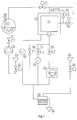
- the steam steriliser is composed of the following components:
- the control system comprises a programmable controller connected to the temperature and pressure sensors, to the solenoid valves, to the contactors, to the relays, to the position sensors, to the level sensors and connected to a touch screen interface for the management of the steriliser.
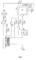
- Figure 2 represents the functional diagram of a further embodiment of the steriliser, wherein the numerals refer to components in line with those of Key 1.
- the cooling system does not use mains water as exchange fluid, not therefore requiring pipes for the feeding of water and connections.
- the general objective of the mechanical embodiment consists in the reduction in the weights and overall dimensions. Materials are therefore used which have a good mechanical strength and resistance to corrosion and which have a low specific weight, to obtain a structure able to resist a pressure of 4,500 absolute mbar, meeting all requirements of the existing directives (PED).
- the overall dimensions have been improved with a redistribution of the structural components.
- the remaining 12 + 12 cm represent the maximum limit of thickness of the walls of the chamber, the height of the interspace and the external thermal insulation. If a thickness of approximately 3 cm of heat-insulating lagging is hypothesised, the total height of the interspace must be approximately 8 cm.
- Weights are optimised with the use of materials whose specific weight is smaller than those currently used and having an equal or improved modulus of resistance, and with a reduction in the mass of the chamber by reducing the thicknesses, although resisting the test pressures as required by the PED directive.
- the block of closure/opening for access to the treatment chamber is made up of two doors in AISI 316L stainless steel connected to a counterweights balancing system and actuated by pneumatic cylinders and by two silicone seals which are dynamically thrust on the surface of the door.
- the treatment space (sterilisation chamber) is made up of a parallelepiped in AISI 316L stainless steel measuring 660x660x1000 mm. (6 sterilisation modules, EN285:2006)
- Figure 3 is a schematic representation of the pump.
- the pump 1 is provided with a stator body 2 containing an eccentric rotor 3 with bearings to facilitate its rotation and at least one blade 4, with an aspiration conduit 5, and a discharge one 6.
- the pump 1 is also provided with a lubrication circuit 7, comprising a storage tank 8 with an intake point 9 of the lubricant fluid (M) placed on its base and an aspiration chamber 10.
- the storage tank 8 can be provided at its base with a thermostat-controlled heating resistor 11 and a coalescence filter 12, able to separate the vapours of the lubricant fluid, recovering them in the same tank.
- the flow of steam traverses the filter 12 together with the non-condensable gases and with them is conveyed to the outlet 13.
- the pump 1 is provided with appropriate sealing means, for opening and closure of conduits, such as valves, diaphragms and oil guards.
- the lubricant fluid (M) is drawn through vacuum from the intake point 9 of the tank 8 towards the aspiration chamber 10, thus ensuring a constant and optimal lubrication of the rotor 3/stator 2/blades 4 assembly and of all the other components, such as valves, diaphragms, oil guards, bearings, etc., required for the proper functioning of the pump 1.
- the pump is also provided with a gas ballast device 14, placed at the base of the stator 2, for the automatic disposal of the residues of humidity present in the lubricant fluid.
- the force of cohesion of the fluid (M) with the surfaces of the mechanical elements of the pump 1 prevents the steam aspirated from the conduit 5 from scouring them, ensuring constant lubrication thereof.
- the condensation in input from the aspiration conduit 5 is pumped with the air and the steam and, together with the vapours of the lubricant fluid (M), is conveyed into the storage tank 8.
- the fluid is drawn by means of the intake point 9, due to a difference in pressure, inside the aspiration chamber 10 of the pump 1.
- the pump constantly succeeds, even after having performed repeated cycles of pumping of the steam, in reaching a high degree of vacuum in the aspiration conduit 5.
- the device 14 known as "gas ballast” allows automatic disposal of the residues of humidity present in the lubricant fluid (M).
- the feeding of air via the device 14 reduces the partial pressure of the condensable gases present in the mixture during compression. In this way their transformation into the liquid phases is avoided, facilitating their expulsion and preventing them from mixing with the lubricant fluid.
- An effective coalescence filter 12 placed at the discharge, separates the vapours of the lubricant fluid, recovering them in the bath of the tank.
- the flow of steam traverses the filter together with the non-condensable gases and with them is conveyed to the outlet 13. Any condensation that remains inside the tank is arranged floating on the lubricant liquid in the tank from where, due to the high temperature of the fluid, it is re-circulated in the form of steam and disposed through the outlet 13.
- the efficacy of the filter reduces to negligible values the consumption of lubricant fluid used, contributing to the safeguarding of the surrounding environment.
- a thermostat-controlled heating resistor 11 was inserted in the fluid storage tank 8. In this way the latent heat of evaporation is supplied, necessary for disposal of the excess condensation present on the bath.
- the seals, diaphragms, blades, oil guards, bearings, etc. are made with materials resistant to temperatures of continuous operation of at least 130°C.
- the body of the pump functions without the forced cooling system, obtaining an increase of approximately 30°C of the temperature value under normal conditions.
- Cooling in traditional pumps lubricated with mineral oil, serves to keep the working temperature low so as to avoid overheating and consequent loss of the lubricating power of the oil.
- the pump of the invention has instead to work at high temperatures, above 100°C, to prevent condensation of the aspirated steam and to reduce to a minimum the presence of residual humidity in the lubricant fluid (M).
- the lubricant fluid used Fomblin (Solvay Solexis), has high specific weight, more than double that of mineral oil, and has a very high chemical stability at high temperatures, with outstanding anti-emulsifying and antioxidant properties.
- the lubricant fluid (M) can be mixed in a defined proportion, with a specific additive which confers antioxidant properties to the metal surfaces of the pump. In this way the formation of rust and encrustations is avoided.
- the pump 1 is also made in a hermetic version (without oil guards) with transmission of the rotary motor/pump movement via a magnetic joint.
- the benefits obtained from the making of this version relate to safety and the reliability of operation of the pump. In fact the risk of leakage of the fluid due to a possible breakage of the oil guards is eliminated in full; moreover the operations of maintenance are limited to only a periodical check on the level of the lubricant and an overhaul for cleaning and replacement of the seals in the medium-long term.
- the embodiment of a steam generator with low consumption involves the use of materials with high heat conductivity (for example aluminium, for the body of the generator) and an outstanding resistance to corrosion (for example steel, for the elements for heating of the water), and also the construction of a structure with high thermal inertia.
- materials with high heat conductivity for example aluminium, for the body of the generator
- an outstanding resistance to corrosion for example steel, for the elements for heating of the water
- Traditional electric steam generators are composed of a cylindrical container in steel wherein treated water is fed by means of an external pump, and later heated by immersed electric resistors until it evaporates.
- the level of the water inside the generator is controlled by means of mechanical float level sensors or by electronic conductivity control.
- the exchange thermal energy between the electric resistors and the water is due to the contact surface of the heating elements.
- a steam generator installed for the operation of a 450 litre steriliser has a power which varies from 27 KW up to 45KW and has a volume of approximately 75 litres.
- a generator has been developed which is able to transfer as fast as possible the thermal energy of the elements for heating the water by means of a single body with high thermal inertia.
- materials such as series 6000 aluminium or copper or other materials featuring high heat conductivity can advantageously be used.
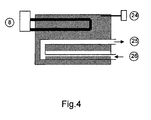
- the heating resistors and a coil for feeding water and constant removal of steam are inserted, as well as a system for the control of the temperature.
- a level control system is not required in that the water fed into the inside by means of a pump is vaporised instantaneously.
- the temperature of regulation of the body is established after a series of working tests on an optimal value for the correct and total evaporation of the water fed.
- the heating elements are made together with the body, with a scalar modular system. In this way it is possible to install a proportionally correct power also for sterilisers of different dimensions.
- FIG. 4 is a schematic representation of the steam generator.
- the cooling system does not use mains water as an exchange fluid.
- the system for cooling the discharge effluent used is usually made up of a container wherein the "hot" discharges (steam at 143°C and condensation at 100°C) is conveyed, cooled by means of water from the mains to a temperature lower than 60°C.
- These devices serve to avoid costly building work to produce discharges resistant to high temperatures, over 60°C.
- the cooling system developed avoids the use of mains water as exchange fluid.
- the heat energy of the discharges is recovered and is conveyed in the treated water which is fed into the generator and later vaporised.
- This system allows a lower consumption of electrical energy by the steam generator, since it uses water which is already preheated.
- the discharge condensation and steam bring the temperature of the treated water in the tank to approximately 60°C.
- the system of cooling lowers the temperature by means of the exchange elements.
- the system of cooling can also be made via a compromise between the various systems mentioned, with the primary objective of avoiding the need for adding discharges of any kind in the atmosphere or network. For example a system of cryopumping has been produced, combined with a system of cooling with air of reduced unit.
- This phase serves to remove the air inside the sterilisation chamber and from the material, to ensure the presence of saturated steam during sterilisation.
- the air is removed by the vacuum pump described above; the lower the pressure reached during this phase, the better the heat distribution during sterilisation.
- the autoclave is able to reach conditions of high vacuum and therefore the sequence of pulsations of steam/vacuum typical of the conditioning phase of the traditional sterilisation autoclaves (not with high vacuum) is no longer necessary.
- the steam/vacuum pulsations have been necessary to date because they encourage the extraction of the air and the penetration of steam inside the masses to be sterilised, as compensation of the insufficient degree of vacuum that can be obtained to date. As a result this phase of the process is faster, with a saving in the times of the entire sterilisation cycle.
- This phase brings the temperature of the chamber, and the load inside it, to the set one established for sterilisation.
Landscapes
- Health & Medical Sciences (AREA)
- Epidemiology (AREA)
- Life Sciences & Earth Sciences (AREA)
- Animal Behavior & Ethology (AREA)
- General Health & Medical Sciences (AREA)
- Public Health (AREA)
- Veterinary Medicine (AREA)
- Engineering & Computer Science (AREA)
- Mechanical Engineering (AREA)
- General Engineering & Computer Science (AREA)
- Apparatus For Disinfection Or Sterilisation (AREA)
- Applications Or Details Of Rotary Compressors (AREA)
Priority Applications (18)
| Application Number | Priority Date | Filing Date | Title |
|---|---|---|---|
| PL07120581T PL2060275T3 (pl) | 2007-11-13 | 2007-11-13 | Instalacja do sterylizowania parowego |
| ES07120581T ES2343906T3 (es) | 2007-11-13 | 2007-11-13 | Sistema de esterilizacion por vapor. |
| RSP-2010/0303A RS51410B (sr) | 2007-11-13 | 2007-11-13 | Sistem za sterilizaciju parom |
| EP07120581A EP2060275B1 (fr) | 2007-11-13 | 2007-11-13 | Système de stérilisation à la vapeur |
| PT07120581T PT2060275E (pt) | 2007-11-13 | 2007-11-13 | Sistema de esterilização por vapor |
| AT07120581T ATE467426T1 (de) | 2007-11-13 | 2007-11-13 | Dampfsterilisationssystem |
| DE602007006517T DE602007006517D1 (de) | 2007-11-13 | 2007-11-13 | Dampfsterilisationssystem |
| US12/265,401 US20090123341A1 (en) | 2007-11-13 | 2008-11-05 | Steam sterilizing system |
| CA2643259A CA2643259C (fr) | 2007-11-13 | 2008-11-06 | Sterilisateur a la vapeur |
| AU2008243173A AU2008243173A1 (en) | 2007-11-13 | 2008-11-07 | Steam sterilizing system |
| ZA200809560A ZA200809560B (en) | 2007-11-13 | 2008-11-10 | Steam sterilizing system |
| KR1020080111596A KR101534017B1 (ko) | 2007-11-13 | 2008-11-11 | 스팀 멸균 시스템 |
| JP2008289995A JP2009119270A (ja) | 2007-11-13 | 2008-11-12 | 水蒸気滅菌システム |
| EA200802143A EA014945B1 (ru) | 2007-11-13 | 2008-11-12 | Система паровой стерилизации |
| MX2008014526A MX2008014526A (es) | 2007-11-13 | 2008-11-13 | Sistema de esterilizacion de vapor. |
| ARP080104944A AR070760A1 (es) | 2007-11-13 | 2008-11-13 | Sistema de esterilizacion con vapor |
| CN2008101764816A CN101433728B (zh) | 2007-11-13 | 2008-11-13 | 蒸汽灭菌系统 |
| BRPI0804918-1A BRPI0804918B1 (pt) | 2007-11-13 | 2008-11-13 | Esterilizador a vapor |
Applications Claiming Priority (1)
| Application Number | Priority Date | Filing Date | Title |
|---|---|---|---|
| EP07120581A EP2060275B1 (fr) | 2007-11-13 | 2007-11-13 | Système de stérilisation à la vapeur |
Publications (2)
| Publication Number | Publication Date |
|---|---|
| EP2060275A1 true EP2060275A1 (fr) | 2009-05-20 |
| EP2060275B1 EP2060275B1 (fr) | 2010-05-12 |
Family
ID=39277957
Family Applications (1)
| Application Number | Title | Priority Date | Filing Date |
|---|---|---|---|
| EP07120581A Active EP2060275B1 (fr) | 2007-11-13 | 2007-11-13 | Système de stérilisation à la vapeur |
Country Status (18)
| Country | Link |
|---|---|
| US (1) | US20090123341A1 (fr) |
| EP (1) | EP2060275B1 (fr) |
| JP (1) | JP2009119270A (fr) |
| KR (1) | KR101534017B1 (fr) |
| CN (1) | CN101433728B (fr) |
| AR (1) | AR070760A1 (fr) |
| AT (1) | ATE467426T1 (fr) |
| AU (1) | AU2008243173A1 (fr) |
| BR (1) | BRPI0804918B1 (fr) |
| CA (1) | CA2643259C (fr) |
| DE (1) | DE602007006517D1 (fr) |
| EA (1) | EA014945B1 (fr) |
| ES (1) | ES2343906T3 (fr) |
| MX (1) | MX2008014526A (fr) |
| PL (1) | PL2060275T3 (fr) |
| PT (1) | PT2060275E (fr) |
| RS (1) | RS51410B (fr) |
| ZA (1) | ZA200809560B (fr) |
Cited By (5)
| Publication number | Priority date | Publication date | Assignee | Title |
|---|---|---|---|---|
| ITNA20090066A1 (it) * | 2009-10-27 | 2011-04-28 | Adiramef S R L | Sistema per la sterilizzazione assoluta con ciclo combinato al vapor saturo ed al gas plasma di ossigeno. |
| WO2014131827A1 (fr) * | 2013-02-28 | 2014-09-04 | Meiko Maschinenbau Gmbh & Co. Kg | Dispositif de nettoyage destiné à nettoyer des contenants à déjections humaines |
| ITMI20131023A1 (it) * | 2013-06-20 | 2014-12-21 | Absolute Up S R L | Sterilizzatrice a vapore |
| IT201900006611A1 (it) * | 2019-05-07 | 2020-11-07 | Icos Pharma S P A | Procedimento di pulizia di un apparato di trattamento di oggetti sfusi e relativo apparato |
| WO2026013607A1 (fr) | 2024-07-10 | 2026-01-15 | Cisa Production S.R.L. | Système de vide |
Families Citing this family (23)
| Publication number | Priority date | Publication date | Assignee | Title |
|---|---|---|---|---|
| WO2010130238A2 (fr) * | 2009-05-15 | 2010-11-18 | Ixetic Hückeswagen Gmbh | Pompe à vide |
| CN101879319B (zh) * | 2010-06-24 | 2013-10-09 | 美的集团股份有限公司 | 一种家用蒸汽清洁消毒设备 |
| CN102018966B (zh) * | 2010-12-27 | 2013-06-19 | 杭州优尼克消毒设备有限公司 | 一种灭菌前预处理装置及工艺 |
| CN102133411A (zh) * | 2011-03-18 | 2011-07-27 | 上海沃迪科技有限公司 | 一种灭菌装置 |
| US20140252101A1 (en) * | 2012-04-28 | 2014-09-11 | George Nicholas Kiouzellis | Automatic control of steam heating systems using remote sensors and switches utilizing thermodynamic qualities of steam with the existing system characteristics to increase heating cycle efficiency |
| CN105026758B (zh) * | 2013-01-21 | 2017-08-01 | 施特林工业咨询公司 | 泵组件和用于将充满蒸汽的腔室抽空的方法 |
| KR20150111984A (ko) * | 2013-01-30 | 2015-10-06 | 네스텍 소시에테아노님 | 식품 가공 중 원하지 않는 온도 변화들을 완화하기 위한 시스템들 및 방법들 |
| CN103330953B (zh) * | 2013-06-10 | 2015-05-20 | 威海威高海盛医用设备有限公司 | 生物安全型脉动真空灭菌器 |
| CN103394106B (zh) * | 2013-07-30 | 2015-04-08 | 山东新华医疗器械股份有限公司 | 蒸汽消毒器及消毒工艺 |
| CN103432606B (zh) * | 2013-08-12 | 2016-08-31 | 武汉合缘绿色生物股份有限公司 | 具有负压冷却装置的旋转式灭菌系统及灭菌方法 |
| BR102013030702B1 (pt) * | 2013-11-28 | 2019-12-24 | Cisabrasile Ltda | sistema de vácuo para equipamentos de esterilização sem utilização de água ilimitado ao vapor saturado |
| RU2659840C1 (ru) * | 2017-04-25 | 2018-07-04 | Федеральное государственное бюджетное образовательное учреждение высшего образования "Российский государственный университет туризма и сервиса" (ФГБОУ ВО "РГУТИС") | Стенд для исследования параметров функционирования бытовых тепловых насосов |
| UY38573A (es) | 2019-03-05 | 2020-09-30 | Grifols Worldwide Operations Ltd | Procedimiento de preparación de contenedores de productos hemoderivados |
| BE1028138B1 (nl) | 2020-03-10 | 2021-10-11 | Atlas Copco Airpower Nv | Smeermiddelrecuperatiesysteem en vacuümsysteem omvattende dergelijke smeermiddelrecuperatiesysteem |
| CN111847734A (zh) * | 2020-05-25 | 2020-10-30 | 安徽普偌森环保科技有限公司 | 一种城镇医疗污水集中处理设备 |
| KR102427908B1 (ko) | 2020-11-11 | 2022-08-03 | 주식회사 챔버 | 고압 스팀 멸균 장치 |
| CN112316162B (zh) * | 2020-11-26 | 2024-09-27 | 山东新华医疗器械股份有限公司 | 一种脉动真空灭菌器及其真空循环系统 |
| CN113476621A (zh) * | 2021-06-07 | 2021-10-08 | 湖南杰萃生物技术有限公司 | 一种植物生料的灭菌方法 |
| CN113577319B (zh) * | 2021-08-05 | 2023-02-24 | 陶陶 | 真空带式干燥机组的进料混合灭菌装置及进料灭菌方法 |
| CN113757119A (zh) * | 2021-11-09 | 2021-12-07 | 杭州智科精密机械有限公司 | 带检测功能的新能源汽车真空泵 |
| CN114313475B (zh) * | 2022-01-13 | 2024-03-29 | 湖北津药药业股份有限公司 | 一种大输液的全自动生产线 |
| CN116421761B (zh) * | 2023-03-29 | 2025-09-12 | 辽宁成大生物股份有限公司 | 一种湿热灭菌器的灭菌评价方法 |
| CN119770688A (zh) * | 2025-03-07 | 2025-04-08 | 南京鑫长江制药设备有限公司 | 一种脉动式医药灭菌柜 |
Citations (3)
| Publication number | Priority date | Publication date | Assignee | Title |
|---|---|---|---|---|
| GB1535058A (en) * | 1974-12-09 | 1978-12-06 | Gen Signal Corp | Vacuum pump with oil separator |
| DE19830706A1 (de) * | 1998-07-09 | 2000-01-13 | Knf Neuberger Gmbh | Vorrichtung zur Dampfsterilisation |
| EP1032432A2 (fr) * | 1997-11-21 | 2000-09-06 | Mmm Münchener Medizin Mechanik Gmbh | Procede de sterilisation a la vapeur et de desinfection a la vapeur et dispositif pour mettre en oeuvre ledit procede |
Family Cites Families (11)
| Publication number | Priority date | Publication date | Assignee | Title |
|---|---|---|---|---|
| US3415445A (en) * | 1966-11-21 | 1968-12-10 | Pennsalt Chemicals Corp | Industrial process and apparatus |
| RU2073526C1 (ru) * | 1993-02-04 | 1997-02-20 | Государственный научно-исследовательский институт экстремальной медицины, полевой фармации и медицинской техники | Стерилизатор |
| EP0686400A1 (fr) * | 1994-06-10 | 1995-12-13 | C. STIEFENHOFER GmbH | Stérilisateur à vapeur avec récupération de chaleur |
| US5868999A (en) * | 1996-03-19 | 1999-02-09 | Ozone Sterilization Products, Inc. | Ozone sterilizer and method for ozone sterilization |
| AU765282C (en) * | 1999-07-21 | 2004-03-25 | Ono Foods Industrial Co., Ltd. | Heating, cooking and disinfecting apparatus |
| CN2422962Y (zh) * | 2000-04-28 | 2001-03-14 | 陈梅生 | 真空高温灭菌器 |
| DE10126634A1 (de) * | 2001-05-31 | 2002-12-12 | Siemens Ag | Dampfsterilisator |
| ES2294095T3 (es) * | 2001-07-03 | 2008-04-01 | W & H STERILIZATION S.R.L. | Disposicion para sistemas de autoclave. |
| JP2003260117A (ja) * | 2002-03-08 | 2003-09-16 | Olympus Optical Co Ltd | 滅菌装置 |
| CN2915117Y (zh) * | 2006-03-16 | 2007-06-27 | 史佩敏 | 真空蒸汽灭菌器 |
| CN100431616C (zh) * | 2006-09-26 | 2008-11-12 | 中国人民解放军第三军医大学第一附属医院 | 灭菌用高纯度压力蒸汽发生装置 |
-
2007
- 2007-11-13 DE DE602007006517T patent/DE602007006517D1/de active Active
- 2007-11-13 ES ES07120581T patent/ES2343906T3/es active Active
- 2007-11-13 PL PL07120581T patent/PL2060275T3/pl unknown
- 2007-11-13 AT AT07120581T patent/ATE467426T1/de active
- 2007-11-13 RS RSP-2010/0303A patent/RS51410B/sr unknown
- 2007-11-13 PT PT07120581T patent/PT2060275E/pt unknown
- 2007-11-13 EP EP07120581A patent/EP2060275B1/fr active Active
-
2008
- 2008-11-05 US US12/265,401 patent/US20090123341A1/en not_active Abandoned
- 2008-11-06 CA CA2643259A patent/CA2643259C/fr not_active Expired - Fee Related
- 2008-11-07 AU AU2008243173A patent/AU2008243173A1/en not_active Abandoned
- 2008-11-10 ZA ZA200809560A patent/ZA200809560B/en unknown
- 2008-11-11 KR KR1020080111596A patent/KR101534017B1/ko not_active Expired - Fee Related
- 2008-11-12 EA EA200802143A patent/EA014945B1/ru not_active IP Right Cessation
- 2008-11-12 JP JP2008289995A patent/JP2009119270A/ja active Pending
- 2008-11-13 AR ARP080104944A patent/AR070760A1/es unknown
- 2008-11-13 CN CN2008101764816A patent/CN101433728B/zh not_active Expired - Fee Related
- 2008-11-13 BR BRPI0804918-1A patent/BRPI0804918B1/pt not_active IP Right Cessation
- 2008-11-13 MX MX2008014526A patent/MX2008014526A/es active IP Right Grant
Patent Citations (3)
| Publication number | Priority date | Publication date | Assignee | Title |
|---|---|---|---|---|
| GB1535058A (en) * | 1974-12-09 | 1978-12-06 | Gen Signal Corp | Vacuum pump with oil separator |
| EP1032432A2 (fr) * | 1997-11-21 | 2000-09-06 | Mmm Münchener Medizin Mechanik Gmbh | Procede de sterilisation a la vapeur et de desinfection a la vapeur et dispositif pour mettre en oeuvre ledit procede |
| DE19830706A1 (de) * | 1998-07-09 | 2000-01-13 | Knf Neuberger Gmbh | Vorrichtung zur Dampfsterilisation |
Cited By (6)
| Publication number | Priority date | Publication date | Assignee | Title |
|---|---|---|---|---|
| ITNA20090066A1 (it) * | 2009-10-27 | 2011-04-28 | Adiramef S R L | Sistema per la sterilizzazione assoluta con ciclo combinato al vapor saturo ed al gas plasma di ossigeno. |
| WO2014131827A1 (fr) * | 2013-02-28 | 2014-09-04 | Meiko Maschinenbau Gmbh & Co. Kg | Dispositif de nettoyage destiné à nettoyer des contenants à déjections humaines |
| ITMI20131023A1 (it) * | 2013-06-20 | 2014-12-21 | Absolute Up S R L | Sterilizzatrice a vapore |
| IT201900006611A1 (it) * | 2019-05-07 | 2020-11-07 | Icos Pharma S P A | Procedimento di pulizia di un apparato di trattamento di oggetti sfusi e relativo apparato |
| EP3736055A1 (fr) * | 2019-05-07 | 2020-11-11 | Icos Pharma S.p.A. | Procédé de nettoyage d'un appareil pour traiter des objets en vrac et appareil correspondant |
| WO2026013607A1 (fr) | 2024-07-10 | 2026-01-15 | Cisa Production S.R.L. | Système de vide |
Also Published As
| Publication number | Publication date |
|---|---|
| JP2009119270A (ja) | 2009-06-04 |
| US20090123341A1 (en) | 2009-05-14 |
| MX2008014526A (es) | 2009-05-26 |
| EP2060275B1 (fr) | 2010-05-12 |
| CN101433728A (zh) | 2009-05-20 |
| EA014945B1 (ru) | 2011-04-29 |
| ZA200809560B (en) | 2009-11-25 |
| BRPI0804918B1 (pt) | 2015-08-25 |
| CA2643259A1 (fr) | 2009-05-13 |
| KR20090049544A (ko) | 2009-05-18 |
| CN101433728B (zh) | 2013-05-01 |
| PL2060275T3 (pl) | 2010-10-29 |
| DE602007006517D1 (de) | 2010-06-24 |
| BRPI0804918A2 (pt) | 2010-07-27 |
| EA200802143A3 (ru) | 2009-08-28 |
| ES2343906T3 (es) | 2010-08-12 |
| EA200802143A2 (ru) | 2009-06-30 |
| KR101534017B1 (ko) | 2015-07-06 |
| ATE467426T1 (de) | 2010-05-15 |
| CA2643259C (fr) | 2016-06-07 |
| AR070760A1 (es) | 2010-05-05 |
| PT2060275E (pt) | 2010-08-04 |
| AU2008243173A1 (en) | 2009-05-28 |
| RS51410B (sr) | 2011-02-28 |
Similar Documents
| Publication | Publication Date | Title |
|---|---|---|
| EP2060275B1 (fr) | Système de stérilisation à la vapeur | |
| CN101658740B (zh) | 压力蒸汽循环液体蒸馏器 | |
| KR102231839B1 (ko) | 음식물 쓰레기를 탈수시키기 위한 처리 시스템 | |
| US20080105610A1 (en) | Pressurized Vapor Cycle Liquid Distillation | |
| EP2060790A1 (fr) | Pompe à vide poussée pour pomper de la vapeur saturée à haute température. | |
| US5265432A (en) | Oil purifying device for use with a refrigeration system | |
| CN112691395B (zh) | 一种多级浓缩的处理设备 | |
| CN115978518A (zh) | 一种高效电磁蒸汽发生器 | |
| Rodrigues et al. | Influence of water temperature in vacuum pumps used for air removal in steam sterilizer | |
| CN215403195U (zh) | 一种低温蒸发器 | |
| RU2187858C1 (ru) | Способ очистки трансформатора от электроизоляционной жидкости на основе полихлорбифенила и устройство для его осуществления | |
| CN112939126A (zh) | 一种浓缩处理方法 | |
| RU2105252C1 (ru) | Холодильная установка | |
| JP3941017B2 (ja) | 液体濃縮方法 | |
| CN111299297A (zh) | 一种病死畜禽无害化处理机的蒸气收集处理装置及方法 | |
| CN216038724U (zh) | 一种工业废水处理设备 | |
| CN219792575U (zh) | 一种真空低温蒸发器制热制冷系统 | |
| CN112604314B (zh) | 一种含油溶剂真空蒸发单元、含油溶剂回收系统及含油溶剂回收方法 | |
| CN214714382U (zh) | 一种含油溶剂真空蒸发单元及含油溶剂回收系统 | |
| CN215440347U (zh) | 一种废润滑油再生组合蒸馏装置 | |
| CN113633792B (zh) | 一种具有生物排放安全性的灭菌器排气处理装置及其工作方法 | |
| RU2285869C2 (ru) | Холодильная установка с насосно-циркуляционной системой охлаждения | |
| CN112156504A (zh) | 一种真空相变锅炉工质脱气装置及其脱气方法 | |
| JP2026001697A (ja) | 冷凍装置及び冷凍サイクルシステム | |
| CN115773488A (zh) | 一种洁净式高效蒸汽热泵机组及其控制方法 |
Legal Events
| Date | Code | Title | Description |
|---|---|---|---|
| PUAI | Public reference made under article 153(3) epc to a published international application that has entered the european phase |
Free format text: ORIGINAL CODE: 0009012 |
|
| AK | Designated contracting states |
Kind code of ref document: A1 Designated state(s): AT BE BG CH CY CZ DE DK EE ES FI FR GB GR HU IE IS IT LI LT LU LV MC MT NL PL PT RO SE SI SK TR |
|
| AX | Request for extension of the european patent |
Extension state: AL BA HR MK RS |
|
| 17P | Request for examination filed |
Effective date: 20090915 |
|
| GRAP | Despatch of communication of intention to grant a patent |
Free format text: ORIGINAL CODE: EPIDOSNIGR1 |
|
| AKX | Designation fees paid |
Designated state(s): AT BE BG CH CY CZ DE DK EE ES FI FR GB GR HU IE IS IT LI LT LU LV MC MT NL PL PT RO SE SI SK TR |
|
| AXX | Extension fees paid |
Extension state: RS Payment date: 20090915 Extension state: BA Payment date: 20090915 Extension state: MK Payment date: 20090915 |
|
| GRAS | Grant fee paid |
Free format text: ORIGINAL CODE: EPIDOSNIGR3 |
|
| GRAA | (expected) grant |
Free format text: ORIGINAL CODE: 0009210 |
|
| AK | Designated contracting states |
Kind code of ref document: B1 Designated state(s): AT BE BG CH CY CZ DE DK EE ES FI FR GB GR HU IE IS IT LI LT LU LV MC MT NL PL PT RO SE SI SK TR |
|
| AX | Request for extension of the european patent |
Extension state: BA MK RS |
|
| REG | Reference to a national code |
Ref country code: GB Ref legal event code: FG4D |
|
| REG | Reference to a national code |
Ref country code: CH Ref legal event code: EP |
|
| REG | Reference to a national code |
Ref country code: IE Ref legal event code: FG4D |
|
| REF | Corresponds to: |
Ref document number: 602007006517 Country of ref document: DE Date of ref document: 20100624 Kind code of ref document: P |
|
| REG | Reference to a national code |
Ref country code: CH Ref legal event code: NV Representative=s name: GRIFFES CONSULTING SA |
|
| REG | Reference to a national code |
Ref country code: RO Ref legal event code: EPE |
|
| REG | Reference to a national code |
Ref country code: SE Ref legal event code: TRGR |
|
| REG | Reference to a national code |
Ref country code: PT Ref legal event code: SC4A Free format text: AVAILABILITY OF NATIONAL TRANSLATION Effective date: 20100728 |
|
| REG | Reference to a national code |
Ref country code: ES Ref legal event code: FG2A Ref document number: 2343906 Country of ref document: ES Kind code of ref document: T3 |
|
| REG | Reference to a national code |
Ref country code: NL Ref legal event code: T3 |
|
| REG | Reference to a national code |
Ref country code: GR Ref legal event code: EP Ref document number: 20100401850 Country of ref document: GR |
|
| LTIE | Lt: invalidation of european patent or patent extension |
Effective date: 20100512 |
|
| PG25 | Lapsed in a contracting state [announced via postgrant information from national office to epo] |
Ref country code: LT Free format text: LAPSE BECAUSE OF FAILURE TO SUBMIT A TRANSLATION OF THE DESCRIPTION OR TO PAY THE FEE WITHIN THE PRESCRIBED TIME-LIMIT Effective date: 20100512 |
|
| REG | Reference to a national code |
Ref country code: PL Ref legal event code: T3 |
|
| PG25 | Lapsed in a contracting state [announced via postgrant information from national office to epo] |
Ref country code: SI Free format text: LAPSE BECAUSE OF FAILURE TO SUBMIT A TRANSLATION OF THE DESCRIPTION OR TO PAY THE FEE WITHIN THE PRESCRIBED TIME-LIMIT Effective date: 20100512 Ref country code: IS Free format text: LAPSE BECAUSE OF FAILURE TO SUBMIT A TRANSLATION OF THE DESCRIPTION OR TO PAY THE FEE WITHIN THE PRESCRIBED TIME-LIMIT Effective date: 20100912 Ref country code: FI Free format text: LAPSE BECAUSE OF FAILURE TO SUBMIT A TRANSLATION OF THE DESCRIPTION OR TO PAY THE FEE WITHIN THE PRESCRIBED TIME-LIMIT Effective date: 20100512 Ref country code: LV Free format text: LAPSE BECAUSE OF FAILURE TO SUBMIT A TRANSLATION OF THE DESCRIPTION OR TO PAY THE FEE WITHIN THE PRESCRIBED TIME-LIMIT Effective date: 20100512 |
|
| REG | Reference to a national code |
Ref country code: HU Ref legal event code: AG4A Ref document number: E008626 Country of ref document: HU |
|
| PG25 | Lapsed in a contracting state [announced via postgrant information from national office to epo] |
Ref country code: CY Free format text: LAPSE BECAUSE OF FAILURE TO SUBMIT A TRANSLATION OF THE DESCRIPTION OR TO PAY THE FEE WITHIN THE PRESCRIBED TIME-LIMIT Effective date: 20100609 |
|
| PG25 | Lapsed in a contracting state [announced via postgrant information from national office to epo] |
Ref country code: EE Free format text: LAPSE BECAUSE OF FAILURE TO SUBMIT A TRANSLATION OF THE DESCRIPTION OR TO PAY THE FEE WITHIN THE PRESCRIBED TIME-LIMIT Effective date: 20100512 Ref country code: DK Free format text: LAPSE BECAUSE OF FAILURE TO SUBMIT A TRANSLATION OF THE DESCRIPTION OR TO PAY THE FEE WITHIN THE PRESCRIBED TIME-LIMIT Effective date: 20100512 |
|
| PGFP | Annual fee paid to national office [announced via postgrant information from national office to epo] |
Ref country code: NL Payment date: 20101111 Year of fee payment: 4 |
|
| PG25 | Lapsed in a contracting state [announced via postgrant information from national office to epo] |
Ref country code: SK Free format text: LAPSE BECAUSE OF FAILURE TO SUBMIT A TRANSLATION OF THE DESCRIPTION OR TO PAY THE FEE WITHIN THE PRESCRIBED TIME-LIMIT Effective date: 20100512 Ref country code: CZ Free format text: LAPSE BECAUSE OF FAILURE TO SUBMIT A TRANSLATION OF THE DESCRIPTION OR TO PAY THE FEE WITHIN THE PRESCRIBED TIME-LIMIT Effective date: 20100512 |
|
| PGFP | Annual fee paid to national office [announced via postgrant information from national office to epo] |
Ref country code: BG Payment date: 20101115 Year of fee payment: 4 Ref country code: HU Payment date: 20101202 Year of fee payment: 4 Ref country code: PL Payment date: 20101028 Year of fee payment: 4 Ref country code: PT Payment date: 20101105 Year of fee payment: 4 Ref country code: RO Payment date: 20101026 Year of fee payment: 4 |
|
| PLBE | No opposition filed within time limit |
Free format text: ORIGINAL CODE: 0009261 |
|
| STAA | Information on the status of an ep patent application or granted ep patent |
Free format text: STATUS: NO OPPOSITION FILED WITHIN TIME LIMIT |
|
| PGFP | Annual fee paid to national office [announced via postgrant information from national office to epo] |
Ref country code: BE Payment date: 20101117 Year of fee payment: 4 Ref country code: GR Payment date: 20101119 Year of fee payment: 4 Ref country code: SE Payment date: 20101112 Year of fee payment: 4 |
|
| 26N | No opposition filed |
Effective date: 20110215 |
|
| REG | Reference to a national code |
Ref country code: DE Ref legal event code: R097 Ref document number: 602007006517 Country of ref document: DE Effective date: 20110214 |
|
| PG25 | Lapsed in a contracting state [announced via postgrant information from national office to epo] |
Ref country code: MC Free format text: LAPSE BECAUSE OF NON-PAYMENT OF DUE FEES Effective date: 20101130 |
|
| PGFP | Annual fee paid to national office [announced via postgrant information from national office to epo] |
Ref country code: ES Payment date: 20101124 Year of fee payment: 4 |
|
| PG25 | Lapsed in a contracting state [announced via postgrant information from national office to epo] |
Ref country code: IE Free format text: LAPSE BECAUSE OF NON-PAYMENT OF DUE FEES Effective date: 20101113 |
|
| PG25 | Lapsed in a contracting state [announced via postgrant information from national office to epo] |
Ref country code: IT Free format text: LAPSE BECAUSE OF NON-PAYMENT OF DUE FEES Effective date: 20101113 Ref country code: MT Free format text: LAPSE BECAUSE OF FAILURE TO SUBMIT A TRANSLATION OF THE DESCRIPTION OR TO PAY THE FEE WITHIN THE PRESCRIBED TIME-LIMIT Effective date: 20100512 |
|
| REG | Reference to a national code |
Ref country code: PT Ref legal event code: MM4A Free format text: LAPSE DUE TO NON-PAYMENT OF FEES Effective date: 20120514 |
|
| BERE | Be: lapsed |
Owner name: CISA S.P.A. Effective date: 20111130 |
|
| REG | Reference to a national code |
Ref country code: NL Ref legal event code: V1 Effective date: 20120601 |
|
| REG | Reference to a national code |
Ref country code: CH Ref legal event code: PL |
|
| REG | Reference to a national code |
Ref country code: SE Ref legal event code: EUG |
|
| REG | Reference to a national code |
Ref country code: GR Ref legal event code: ML Ref document number: 20100401850 Country of ref document: GR Effective date: 20120605 |
|
| PG25 | Lapsed in a contracting state [announced via postgrant information from national office to epo] |
Ref country code: LI Free format text: LAPSE BECAUSE OF NON-PAYMENT OF DUE FEES Effective date: 20111130 Ref country code: CH Free format text: LAPSE BECAUSE OF NON-PAYMENT OF DUE FEES Effective date: 20111130 Ref country code: NL Free format text: LAPSE BECAUSE OF NON-PAYMENT OF DUE FEES Effective date: 20120601 Ref country code: HU Free format text: LAPSE BECAUSE OF NON-PAYMENT OF DUE FEES Effective date: 20111114 |
|
| PG25 | Lapsed in a contracting state [announced via postgrant information from national office to epo] |
Ref country code: GR Free format text: LAPSE BECAUSE OF NON-PAYMENT OF DUE FEES Effective date: 20120605 Ref country code: RO Free format text: LAPSE BECAUSE OF NON-PAYMENT OF DUE FEES Effective date: 20111113 Ref country code: PT Free format text: LAPSE BECAUSE OF NON-PAYMENT OF DUE FEES Effective date: 20120514 Ref country code: BE Free format text: LAPSE BECAUSE OF NON-PAYMENT OF DUE FEES Effective date: 20111130 |
|
| PG25 | Lapsed in a contracting state [announced via postgrant information from national office to epo] |
Ref country code: LU Free format text: LAPSE BECAUSE OF NON-PAYMENT OF DUE FEES Effective date: 20101113 |
|
| PG25 | Lapsed in a contracting state [announced via postgrant information from national office to epo] |
Ref country code: SE Free format text: LAPSE BECAUSE OF NON-PAYMENT OF DUE FEES Effective date: 20111114 |
|
| PG25 | Lapsed in a contracting state [announced via postgrant information from national office to epo] |
Ref country code: PL Free format text: LAPSE BECAUSE OF NON-PAYMENT OF DUE FEES Effective date: 20111113 |
|
| REG | Reference to a national code |
Ref country code: ES Ref legal event code: FD2A Effective date: 20130716 |
|
| PG25 | Lapsed in a contracting state [announced via postgrant information from national office to epo] |
Ref country code: BG Free format text: LAPSE BECAUSE OF NON-PAYMENT OF DUE FEES Effective date: 20120630 Ref country code: ES Free format text: LAPSE BECAUSE OF NON-PAYMENT OF DUE FEES Effective date: 20111114 |
|
| PGFP | Annual fee paid to national office [announced via postgrant information from national office to epo] |
Ref country code: TR Payment date: 20141107 Year of fee payment: 8 |
|
| REG | Reference to a national code |
Ref country code: FR Ref legal event code: PLFP Year of fee payment: 9 |
|
| REG | Reference to a national code |
Ref country code: FR Ref legal event code: PLFP Year of fee payment: 10 |
|
| REG | Reference to a national code |
Ref country code: FR Ref legal event code: PLFP Year of fee payment: 11 |
|
| PGFP | Annual fee paid to national office [announced via postgrant information from national office to epo] |
Ref country code: GB Payment date: 20211221 Year of fee payment: 15 Ref country code: FR Payment date: 20211220 Year of fee payment: 15 Ref country code: DE Payment date: 20211210 Year of fee payment: 15 Ref country code: AT Payment date: 20211222 Year of fee payment: 15 |
|
| PGFP | Annual fee paid to national office [announced via postgrant information from national office to epo] |
Ref country code: IT Payment date: 20211130 Year of fee payment: 15 |
|
| PG25 | Lapsed in a contracting state [announced via postgrant information from national office to epo] |
Ref country code: TR Free format text: LAPSE BECAUSE OF NON-PAYMENT OF DUE FEES Effective date: 20161113 |
|
| REG | Reference to a national code |
Ref country code: DE Ref legal event code: R119 Ref document number: 602007006517 Country of ref document: DE |
|
| REG | Reference to a national code |
Ref country code: AT Ref legal event code: MM01 Ref document number: 467426 Country of ref document: AT Kind code of ref document: T Effective date: 20221113 |
|
| GBPC | Gb: european patent ceased through non-payment of renewal fee |
Effective date: 20221113 |
|
| PG25 | Lapsed in a contracting state [announced via postgrant information from national office to epo] |
Ref country code: AT Free format text: LAPSE BECAUSE OF NON-PAYMENT OF DUE FEES Effective date: 20221113 |
|
| PG25 | Lapsed in a contracting state [announced via postgrant information from national office to epo] |
Ref country code: IT Free format text: LAPSE BECAUSE OF NON-PAYMENT OF DUE FEES Effective date: 20221113 Ref country code: GB Free format text: LAPSE BECAUSE OF NON-PAYMENT OF DUE FEES Effective date: 20221113 Ref country code: DE Free format text: LAPSE BECAUSE OF NON-PAYMENT OF DUE FEES Effective date: 20230601 |
|
| PG25 | Lapsed in a contracting state [announced via postgrant information from national office to epo] |
Ref country code: FR Free format text: LAPSE BECAUSE OF NON-PAYMENT OF DUE FEES Effective date: 20221130 |