EP2060332A2 - Dispositif d'aspiration pour des matières finement dispersées - Google Patents
Dispositif d'aspiration pour des matières finement dispersées Download PDFInfo
- Publication number
- EP2060332A2 EP2060332A2 EP09003260A EP09003260A EP2060332A2 EP 2060332 A2 EP2060332 A2 EP 2060332A2 EP 09003260 A EP09003260 A EP 09003260A EP 09003260 A EP09003260 A EP 09003260A EP 2060332 A2 EP2060332 A2 EP 2060332A2
- Authority
- EP
- European Patent Office
- Prior art keywords
- suction device
- clamping
- aer
- chamber
- suction
- Prior art date
- Legal status (The legal status is an assumption and is not a legal conclusion. Google has not performed a legal analysis and makes no representation as to the accuracy of the status listed.)
- Granted
Links
- 239000000463 material Substances 0.000 title description 3
- 239000000126 substance Substances 0.000 claims abstract description 8
- 238000005192 partition Methods 0.000 claims description 8
- 230000003993 interaction Effects 0.000 claims 1
- 239000000428 dust Substances 0.000 description 6
- 239000003570 air Substances 0.000 description 4
- 239000000443 aerosol Substances 0.000 description 3
- 238000011109 contamination Methods 0.000 description 3
- 239000004743 Polypropylene Substances 0.000 description 1
- 239000012080 ambient air Substances 0.000 description 1
- 230000015572 biosynthetic process Effects 0.000 description 1
- 239000013590 bulk material Substances 0.000 description 1
- 238000004140 cleaning Methods 0.000 description 1
- 238000010276 construction Methods 0.000 description 1
- 230000000694 effects Effects 0.000 description 1
- 239000002360 explosive Substances 0.000 description 1
- 238000000605 extraction Methods 0.000 description 1
- 239000007789 gas Substances 0.000 description 1
- 239000000383 hazardous chemical Substances 0.000 description 1
- 239000003595 mist Substances 0.000 description 1
- -1 polypropylene Polymers 0.000 description 1
- 229920001155 polypropylene Polymers 0.000 description 1
- 238000000926 separation method Methods 0.000 description 1
- 231100000331 toxic Toxicity 0.000 description 1
- 230000002588 toxic effect Effects 0.000 description 1
- 239000002341 toxic gas Substances 0.000 description 1
Images


Classifications
-
- B—PERFORMING OPERATIONS; TRANSPORTING
- B08—CLEANING
- B08B—CLEANING IN GENERAL; PREVENTION OF FOULING IN GENERAL
- B08B15/00—Preventing escape of dirt or fumes from the area where they are produced; Collecting or removing dirt or fumes from that area
- B08B15/007—Fume suction nozzles arranged on a closed or semi-closed surface, e.g. on a circular, ring-shaped or rectangular surface adjacent the area where fumes are produced
Definitions
- the invention relates to a suction device for finely divided and / or gaseous substances, which is formed as a hollow annular body with a central pour opening, at least one pipe connection leads into the interior of the annular body and in the wall defining the pouring opening a plurality of suction holes is formed, wherein the bores communicate via the interior of the hollow ring body with the pipe connection.
- a suction device of the type mentioned is from the WO 03/045593 A1 known.
- This device is designed for the suction of toxic gases, but does not take into account the problem of sucking powdered substances, especially in connection with the requirements that are made in the pharmaceutical industry.
- the known device would be contaminated in use when filling powdery substances after a short time with deposits , which could hardly be removed from the device, which is usually not allowed for hygienic reasons.
- An object of the invention is to provide an improved suction device which does not have the above-mentioned disadvantages.
- the ring body has at least one upper part and a lower part, wherein the upper part and lower part held together in use by a clamping means and are separable after opening the clamping means exposing the annular body interior.
- a suction device which can be adapted to any filling situation also in size and provides the best possible protection against contamination of the environment by escaping dust and aerosols, with operating errors, such as incorrect positioning of the suction head according to the prior art z. B. can not be effectively prevented by not well trained staff.
- the cleaning is quick and easy to carry out, which is an absolute necessity in many applications, especially in pharmaceutical companies
- the pouring opening is delimited by a lower, substantially cylindrical wall section and an adjoining upper, upwardly and outwardly widened conical wall section, wherein the suction bores are formed in the conical wall section. In this way, an upwardly directed vacuum cone can be built up over the pour opening during operation.
- suction bores have a rounding at least at their outer end region facing the pouring opening.
- the air duct can be kept particularly homogeneous, if that is provided between upper part and lower part partition plate with at least one passage opening, the annular body in the assembled state, at least one lower chamber and at least one upper chamber and the at least one lower chamber and the at least one upper Chamber via at least one passage opening communicate with each other. It is also advantageous if at least one upper, inner, annular chamber and at least one lower, outer chamber are provided, the pipe socket opening into the at least one lower, outer chamber and the suction bores into the at least one upper, inner chamber.
- a further improvement is in this case characterized in that an upper, inner, annular chamber is provided, which communicates with at least one upper, outer chamber portion, and the upper, outer chamber portion communicates with at least one outer, lower chamber via a passage opening of the separation plate, or when a guide surface which leads tangentially outwards is provided at the connection between the upper, inner, annular chamber with the at least one upper, outer chamber portion ,
- the suction device In order to enable rapid disassembly and assembly of the suction device is provided in a variant of the invention that is provided at the connection between the upper, inner, annular chamber with the at least one upper, outer chamber portion, a guide surface leading tangentially outwards.
- the quick-release head has a clamping lever with a supportable against the lower surface of the lower part eccentric surface and can be brought into train with the lower end of the clamping bolt.
- each clamping bolt is cylindrical, wherein the support head is widened with respect to the cross section and the clamping bolt has at the opposite end a passing into a holding head annular groove for cooperation with the quick-release head.
- the tensioning lever has a fork-shaped end with holes in which a transverse bolt is inserted, and a standing with the clamping bolt in conjunction threaded draw bolt is screwed into a radial threaded bore of the transverse bolt.
- an advantageous variant may be characterized in that the clamping lever has a fork-shaped end with holes in which a transverse bolt is inserted, and a standing with the clamping bolt threaded draw bolt is screwed into a radial threaded bore of the transverse bolt.
- the clamping bolt is connected to the threaded pull pin via a clamping piece, the clamping bolt is mounted with its holding head in a slot of the clamping piece and the threaded pull pin is screwed into a radial threaded bore of a clamping pin, in two opposite Holes of the clamping piece is added.
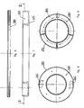
- the shape of the suction device AER corresponds to a hollow ring body, it may also be referred to as toroidal, wherein a central pour opening SOE is bounded by a wall WAN and in this wall a plurality of suction holes ASB is formed, in the present example 50 holes. More precisely, the bores are formed in an upper, upwardly and outwardly conically widened wall section KWA, which merges downward into a substantially cylindrical wall section ZWA.
- the holes ASB are in a manner to be described in more detail below about the interior of the hollow body with a pipe connection, namely a pipe socket in connection ROS in the operating state of the device via a suction line, not shown, such as hose, is connected to a suction device. Thanks to the obliquely upward bores ASB ambient air is sucked in and formed a kind of vacuum cone over the pouring spout.
- the suction holes ASB have a rounding ARU at least at their outer end pointing toward the pouring opening SOE, in the present case, however, at both end regions, by means of which a local vortex formation and thus the noise development are reduced.
- the suction device can be easily cleaned. Therefore, it can be provided that it consists of two or more parts and can be dismantled, which will be described in more detail below.
- the suction device AER consists of at least one upper part OTE and a lower part UTE, wherein the upper part and lower part are held together in the state of use by a clamping device SSM and after opening of the clamping means to expose the annular body interior are separable.
- a separating plate TRP located between the upper part OTE and lower part UTE is provided with at least one passage opening DUT.
- the top part OTE is in the Fig. 3 to 5 shown in detail, the lower part UTE in the FIGS. 7 and 9 and the partition plate TRP in the 6 and 8 ,
- TRP partition plate
- UTE has proven in practice polypropylene, but it should be clear that the skilled person depending on the application, other useful materials are available.
- the annular body of the suction device AER has at least one lower chamber UKA and at least one upper chamber OKA, the at least one lower chamber UKA and the at least one upper chamber OKA communicating with each other via at least one passage opening DUT, in the present example two stand.
- a multi-part upper, inner, annular chamber OKA and a lower, about 180 ° extending outer chamber UKA is provided, wherein the pipe socket ROS in this lower, outer chamber UKA and the suction holes ASB in the upper, inner chamber OKA lead.
- the air together with any existing dust or a gas or aerosol is thus sucked through the suction holes ASB first into the inner, upper chamber OKA and passes from here to outer sections of the chamber, wherein tangentially leading outward guide surfaces LEF (see Fig. 5 ) lead the flow. From these said chamber sections, the air through the openings DUT of the partition plate (see Fig. 8 ) down into the lower, outer chamber UKA (see Fig.
- the air flow rate is on the order of 130 m 3 / h with an outer dimension of the ring body of 480 mm.
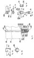
- the quick-release head SSK has a substantially U-shaped clamping piece PLC with two parallel legs SEL. In bores of the two legs a cylindrical clamping pin ZSS is added, which has a lying between the legs, the clamping pin radially passing through threaded hole GBO.
- the two legs SEL are connected at one end via a web STE, in which a slot SLI is formed.
- the clamping bolt SPB is introduced with its holding head HAK, wherein the diameter of the holding head HAK is less than the inner spacing of the legs and the slot width greater than the diameter of the clamping bolt SPB at the location of its annular groove RNT.
- the clamping piece SPS with the clamping pin ZSS lies within a slotted pressure sleeve DRH, which can be supported with an open end via an intermediate disk SEI on the lower part UTE.
- a slotted pressure sleeve DRH which can be supported with an open end via an intermediate disk SEI on the lower part UTE.
- the clamping bolt SPB with the quick release head SSK could also be used upside down. In this case, the pressure sleeve would be supported on the top OTE
- the assembly of the suction device takes place in the manner described below.
- the top OTE is placed with its top on a base, after previously z. B. two clamping bolts SPB were inserted through holes DBO. Then, the partition plate TRP is placed over it, wherein the bolts SPB pass through the associated holes DBO of the partition plate TRP. Finally, the lower part UTE is placed over it so that the free ends of the bolts SPB protrude from its underside. Then the quick release head SSK is pushed with the clamping lever SPH open so that the end of the bolt with the holding head HAK passes through the slot of the pressure sleeve DRH in the slot SLI of the clamping piece SPS. Then the clamping lever SPH is closed by tilting to its end position.
- the clamping force can be adjusted individually, since in this case the Gewindzugbolzen GZB is rotated with respect to the threaded bore GBO in the clamping pin ZSS.
- the remaining clamping bolts SPB and quick release heads SSK can be mounted.
- the dismantling of the device takes place mutatis mutandis after respective opening of the quick release heads SSK.
- a funnel in a poorly closed clamping lever of the quick release head SSK falls, are formed at the ends of the slot SLI of the clamping piece SPS two locking lugs SIN ( Fig. 10f ).
- the support head ASK of the clamping bolt SPB can of course also be designed differently than in Fig. 10
- it may be a hexagon head received in a correspondingly shaped recess of the top OTE.
- the quick release head SSK can also be simpler in construction and, for example, consist only of a spring plate with a slot which is pushed onto the end of the clamping bolt such that the slot comprises the annular groove RNT.
Landscapes
- Hooks, Suction Cups, And Attachment By Adhesive Means (AREA)
- Auxiliary Devices For Machine Tools (AREA)
- Seasonings (AREA)
- Control And Other Processes For Unpacking Of Materials (AREA)
- Manipulator (AREA)
- Cyclones (AREA)
- Disintegrating Or Milling (AREA)
- Vaporization, Distillation, Condensation, Sublimation, And Cold Traps (AREA)
- General Preparation And Processing Of Foods (AREA)
- Reciprocating Pumps (AREA)
- Air Transport Of Granular Materials (AREA)
Priority Applications (1)
| Application Number | Priority Date | Filing Date | Title |
|---|---|---|---|
| SI200730334T SI2060332T1 (sl) | 2006-05-11 | 2007-05-09 | Sesalna naprava za drobno razpršene snovi |
Applications Claiming Priority (2)
| Application Number | Priority Date | Filing Date | Title |
|---|---|---|---|
| AT0081506A AT503587B1 (de) | 2006-05-11 | 2006-05-11 | Absaugeinrichtung für fein verteilte stoffe |
| EP07450086A EP1854560A3 (fr) | 2006-05-11 | 2007-05-09 | Dispositif d'aspiration pour des matières finement dispersées |
Related Parent Applications (2)
| Application Number | Title | Priority Date | Filing Date |
|---|---|---|---|
| EP07450086.9 Division | 2007-05-09 | ||
| EP07450086A Division EP1854560A3 (fr) | 2006-05-11 | 2007-05-09 | Dispositif d'aspiration pour des matières finement dispersées |
Publications (3)
| Publication Number | Publication Date |
|---|---|
| EP2060332A2 true EP2060332A2 (fr) | 2009-05-20 |
| EP2060332A3 EP2060332A3 (fr) | 2009-08-19 |
| EP2060332B1 EP2060332B1 (fr) | 2010-07-07 |
Family
ID=38229331
Family Applications (3)
| Application Number | Title | Priority Date | Filing Date |
|---|---|---|---|
| EP09003260A Not-in-force EP2060332B1 (fr) | 2006-05-11 | 2007-05-09 | Dispositif d'aspiration pour des matières finement dispersées |
| EP09003261A Withdrawn EP2060333A3 (fr) | 2006-05-11 | 2007-05-09 | Dispositif d'aspiration pour des matières finement dispersées |
| EP07450086A Withdrawn EP1854560A3 (fr) | 2006-05-11 | 2007-05-09 | Dispositif d'aspiration pour des matières finement dispersées |
Family Applications After (2)
| Application Number | Title | Priority Date | Filing Date |
|---|---|---|---|
| EP09003261A Withdrawn EP2060333A3 (fr) | 2006-05-11 | 2007-05-09 | Dispositif d'aspiration pour des matières finement dispersées |
| EP07450086A Withdrawn EP1854560A3 (fr) | 2006-05-11 | 2007-05-09 | Dispositif d'aspiration pour des matières finement dispersées |
Country Status (5)
| Country | Link |
|---|---|
| EP (3) | EP2060332B1 (fr) |
| AT (2) | AT503587B1 (fr) |
| DE (1) | DE502007004343D1 (fr) |
| DK (1) | DK2060332T3 (fr) |
| SI (1) | SI2060332T1 (fr) |
Cited By (1)
| Publication number | Priority date | Publication date | Assignee | Title |
|---|---|---|---|---|
| CN104148353A (zh) * | 2014-07-21 | 2014-11-19 | 苏州凯枫瑞电子科技有限公司 | 纺织车间的多点检测除尘系统 |
Families Citing this family (2)
| Publication number | Priority date | Publication date | Assignee | Title |
|---|---|---|---|---|
| CN104164720A (zh) * | 2014-07-21 | 2014-11-26 | 苏州凯枫瑞电子科技有限公司 | 基于灰尘与湿度监控的智能纺织车间除尘系统 |
| CN104190683A (zh) * | 2014-07-21 | 2014-12-10 | 苏州凯枫瑞电子科技有限公司 | 纺织车间的远程清洁系统 |
Citations (1)
| Publication number | Priority date | Publication date | Assignee | Title |
|---|---|---|---|---|
| WO2003045593A1 (fr) | 2001-11-26 | 2003-06-05 | Commissariat A L'energie Atomique | Dispositif d'extraction de gaz. |
Family Cites Families (8)
| Publication number | Priority date | Publication date | Assignee | Title |
|---|---|---|---|---|
| US1981485A (en) * | 1932-04-30 | 1934-11-20 | Stokes Machine Co | Nozzle attachment for powder filling machines |
| FR774735A (fr) * | 1933-06-17 | 1934-12-12 | Cirages Francais Soc Gen Des | Procédé et appareil de remplissage d'une boite ou analogue en matière pulvérulente |
| NL281941A (fr) * | 1962-08-09 | |||
| US4071338A (en) * | 1976-01-27 | 1978-01-31 | Physical Systems, Inc. | Air exhausted mixing bowl |
| US5297739A (en) * | 1987-11-23 | 1994-03-29 | Torus Corporation | Enhanced rising device with circular array of orifices |
| US5348063A (en) * | 1993-01-04 | 1994-09-20 | Semi-Bulk Systems, Inc. | Material handling system |
| FR2729591A1 (fr) * | 1995-01-20 | 1996-07-26 | Rabier Jean Jacques | Dispositif d'aspiration pour aspirer les nuages pulverulents ou pulverises de produit |
| US6171407B1 (en) * | 1999-10-12 | 2001-01-09 | Motorola, Inc. | Ventilation fixture and method of using same |
-
2006
- 2006-05-11 AT AT0081506A patent/AT503587B1/de not_active IP Right Cessation
-
2007
- 2007-05-09 DK DK09003260.8T patent/DK2060332T3/da active
- 2007-05-09 EP EP09003260A patent/EP2060332B1/fr not_active Not-in-force
- 2007-05-09 AT AT09003260T patent/ATE473061T1/de active
- 2007-05-09 DE DE502007004343T patent/DE502007004343D1/de active Active
- 2007-05-09 SI SI200730334T patent/SI2060332T1/sl unknown
- 2007-05-09 EP EP09003261A patent/EP2060333A3/fr not_active Withdrawn
- 2007-05-09 EP EP07450086A patent/EP1854560A3/fr not_active Withdrawn
Patent Citations (1)
| Publication number | Priority date | Publication date | Assignee | Title |
|---|---|---|---|---|
| WO2003045593A1 (fr) | 2001-11-26 | 2003-06-05 | Commissariat A L'energie Atomique | Dispositif d'extraction de gaz. |
Cited By (1)
| Publication number | Priority date | Publication date | Assignee | Title |
|---|---|---|---|---|
| CN104148353A (zh) * | 2014-07-21 | 2014-11-19 | 苏州凯枫瑞电子科技有限公司 | 纺织车间的多点检测除尘系统 |
Also Published As
| Publication number | Publication date |
|---|---|
| DK2060332T3 (da) | 2010-08-09 |
| DE502007004343D1 (de) | 2010-08-19 |
| EP1854560A3 (fr) | 2008-06-11 |
| EP1854560A2 (fr) | 2007-11-14 |
| EP2060333A3 (fr) | 2009-08-19 |
| ATE473061T1 (de) | 2010-07-15 |
| EP2060332B1 (fr) | 2010-07-07 |
| AT503587B1 (de) | 2008-09-15 |
| EP2060332A3 (fr) | 2009-08-19 |
| AT503587A1 (de) | 2007-11-15 |
| SI2060332T1 (sl) | 2010-10-29 |
| EP2060333A2 (fr) | 2009-05-20 |
Similar Documents
| Publication | Publication Date | Title |
|---|---|---|
| EP0440023B1 (fr) | Système de prise d'échantillon comprenant une vanne et une unité de prélèvement | |
| EP0623527B2 (fr) | Récipient pour matériaux en vrac équipé d'une vanne d'évacuation par le fond | |
| EP2542873A1 (fr) | Dispositif pour prélever des échantillons dans un flux de poudre | |
| EP2060332B1 (fr) | Dispositif d'aspiration pour des matières finement dispersées | |
| EP3067126B1 (fr) | Dispositif de rinçage d'un récipient avec un fluide de rinçage | |
| DE2919484C2 (de) | Einrichtung zur Wandabreinigung durch Druckgas bzw. Dampf | |
| EP1871534B1 (fr) | Buse de pulverisation pour dispositif a lit fluidise | |
| EP1742725B1 (fr) | Procede et dispositif de traitement pneumatique de substances pulverulentes | |
| DE19526510A1 (de) | Automatisches Transfersystem | |
| DE3512289C2 (de) | Schüttgutsilo mit entlüfteter Misch- oder Homogenisierkammer | |
| EP3464164B1 (fr) | Système de remplissage de cuves avec récipient intermédiaire | |
| DE1913026A1 (de) | Verfahren und Vorrichtung zur Entleerung von Behaeltern fuer koerniges bzw. staubfoermiges rieselfaehiges Gut mittels Druckgas | |
| DE202005016035U1 (de) | Transfervorrichtung für die Bereitstellung von Prozessstoffen und die Befüllung von Prozessgeräten | |
| DE2634547C3 (de) | Einrichtung an einem Flüssigkeitstank, insbesondere an einem Biertank | |
| EP2112122A2 (fr) | Récipient | |
| DE102017105418B4 (de) | Vorrichtung zur Befüllung von Tanks mit Zwischenbehälter | |
| DE102017105417B4 (de) | Vorrichtung zur Befüllung von Tanks mit Zwischenbehälter | |
| DE102005012288B4 (de) | Vorrichtung zum Entleeren und nachfolgenden Befüllen eines Pulver-Behälters | |
| AT392453B (de) | Vorrichtung zur zufuehrung von inertgas in leere behaelter | |
| DE3736972A1 (de) | Verfahren und vorrichtung zum bewegen granulatartiger hilfsmittel zur behandlung von zahnersatz | |
| DE20304787U1 (de) | Pneumatischer Probenehmer | |
| DE102017105419A1 (de) | Vorrichtung zur Befüllung von Tanks mit Zwischenbehälter | |
| DE202004003650U1 (de) | Entleervorrichtung | |
| DE9207725U1 (de) | Probenheber | |
| DE202007006924U1 (de) | Saugfördereinrichtung |
Legal Events
| Date | Code | Title | Description |
|---|---|---|---|
| PUAI | Public reference made under article 153(3) epc to a published international application that has entered the european phase |
Free format text: ORIGINAL CODE: 0009012 |
|
| AC | Divisional application: reference to earlier application |
Ref document number: 1854560 Country of ref document: EP Kind code of ref document: P |
|
| AK | Designated contracting states |
Kind code of ref document: A2 Designated state(s): AT BE BG CH CY CZ DE DK EE ES FI FR GB GR HU IE IS IT LI LT LU LV MC MT NL PL PT RO SE SI SK TR |
|
| AX | Request for extension of the european patent |
Extension state: AL BA HR MK RS |
|
| PUAL | Search report despatched |
Free format text: ORIGINAL CODE: 0009013 |
|
| AK | Designated contracting states |
Kind code of ref document: A3 Designated state(s): AT BE BG CH CY CZ DE DK EE ES FI FR GB GR HU IE IS IT LI LT LU LV MC MT NL PL PT RO SE SI SK TR |
|
| AX | Request for extension of the european patent |
Extension state: AL BA HR MK RS |
|
| RIC1 | Information provided on ipc code assigned before grant |
Ipc: B08B 15/00 20060101AFI20090331BHEP Ipc: B65B 1/28 20060101ALN20090714BHEP |
|
| 17P | Request for examination filed |
Effective date: 20090808 |
|
| 17Q | First examination report despatched |
Effective date: 20091030 |
|
| GRAP | Despatch of communication of intention to grant a patent |
Free format text: ORIGINAL CODE: EPIDOSNIGR1 |
|
| AKX | Designation fees paid |
Designated state(s): AT BE BG CH CY CZ DE DK EE ES FI FR GB GR HU IE IS IT LI LT LU LV MC MT NL PL PT RO SE SI SK TR |
|
| GRAS | Grant fee paid |
Free format text: ORIGINAL CODE: EPIDOSNIGR3 |
|
| GRAA | (expected) grant |
Free format text: ORIGINAL CODE: 0009210 |
|
| AC | Divisional application: reference to earlier application |
Ref document number: 1854560 Country of ref document: EP Kind code of ref document: P |
|
| AK | Designated contracting states |
Kind code of ref document: B1 Designated state(s): AT BE BG CH CY CZ DE DK EE ES FI FR GB GR HU IE IS IT LI LT LU LV MC MT NL PL PT RO SE SI SK TR |
|
| REG | Reference to a national code |
Ref country code: GB Ref legal event code: FG4D Free format text: NOT ENGLISH |
|
| REG | Reference to a national code |
Ref country code: CH Ref legal event code: EP |
|
| REG | Reference to a national code |
Ref country code: CH Ref legal event code: NV Representative=s name: HANS RUDOLF GACHNANG PATENTANWALT |
|
| REG | Reference to a national code |
Ref country code: DK Ref legal event code: T3 |
|
| REG | Reference to a national code |
Ref country code: IE Ref legal event code: FG4D |
|
| REF | Corresponds to: |
Ref document number: 502007004343 Country of ref document: DE Date of ref document: 20100819 Kind code of ref document: P |
|
| REG | Reference to a national code |
Ref country code: SE Ref legal event code: TRGR |
|
| REG | Reference to a national code |
Ref country code: NL Ref legal event code: T3 |
|
| REG | Reference to a national code |
Ref country code: SE Ref legal event code: RPOT |
|
| LTIE | Lt: invalidation of european patent or patent extension |
Effective date: 20100707 |
|
| PG25 | Lapsed in a contracting state [announced via postgrant information from national office to epo] |
Ref country code: LT Free format text: LAPSE BECAUSE OF FAILURE TO SUBMIT A TRANSLATION OF THE DESCRIPTION OR TO PAY THE FEE WITHIN THE PRESCRIBED TIME-LIMIT Effective date: 20100707 Ref country code: FI Free format text: LAPSE BECAUSE OF FAILURE TO SUBMIT A TRANSLATION OF THE DESCRIPTION OR TO PAY THE FEE WITHIN THE PRESCRIBED TIME-LIMIT Effective date: 20100707 |
|
| REG | Reference to a national code |
Ref country code: IE Ref legal event code: FD4D |
|
| PG25 | Lapsed in a contracting state [announced via postgrant information from national office to epo] |
Ref country code: PT Free format text: LAPSE BECAUSE OF FAILURE TO SUBMIT A TRANSLATION OF THE DESCRIPTION OR TO PAY THE FEE WITHIN THE PRESCRIBED TIME-LIMIT Effective date: 20101108 Ref country code: BG Free format text: LAPSE BECAUSE OF FAILURE TO SUBMIT A TRANSLATION OF THE DESCRIPTION OR TO PAY THE FEE WITHIN THE PRESCRIBED TIME-LIMIT Effective date: 20101007 Ref country code: CY Free format text: LAPSE BECAUSE OF FAILURE TO SUBMIT A TRANSLATION OF THE DESCRIPTION OR TO PAY THE FEE WITHIN THE PRESCRIBED TIME-LIMIT Effective date: 20100707 Ref country code: IS Free format text: LAPSE BECAUSE OF FAILURE TO SUBMIT A TRANSLATION OF THE DESCRIPTION OR TO PAY THE FEE WITHIN THE PRESCRIBED TIME-LIMIT Effective date: 20101107 Ref country code: PL Free format text: LAPSE BECAUSE OF FAILURE TO SUBMIT A TRANSLATION OF THE DESCRIPTION OR TO PAY THE FEE WITHIN THE PRESCRIBED TIME-LIMIT Effective date: 20100707 |
|
| PG25 | Lapsed in a contracting state [announced via postgrant information from national office to epo] |
Ref country code: GR Free format text: LAPSE BECAUSE OF FAILURE TO SUBMIT A TRANSLATION OF THE DESCRIPTION OR TO PAY THE FEE WITHIN THE PRESCRIBED TIME-LIMIT Effective date: 20101008 Ref country code: LV Free format text: LAPSE BECAUSE OF FAILURE TO SUBMIT A TRANSLATION OF THE DESCRIPTION OR TO PAY THE FEE WITHIN THE PRESCRIBED TIME-LIMIT Effective date: 20100707 |
|
| PG25 | Lapsed in a contracting state [announced via postgrant information from national office to epo] |
Ref country code: IE Free format text: LAPSE BECAUSE OF FAILURE TO SUBMIT A TRANSLATION OF THE DESCRIPTION OR TO PAY THE FEE WITHIN THE PRESCRIBED TIME-LIMIT Effective date: 20100707 |
|
| PLBE | No opposition filed within time limit |
Free format text: ORIGINAL CODE: 0009261 |
|
| STAA | Information on the status of an ep patent application or granted ep patent |
Free format text: STATUS: NO OPPOSITION FILED WITHIN TIME LIMIT |
|
| PG25 | Lapsed in a contracting state [announced via postgrant information from national office to epo] |
Ref country code: IT Free format text: LAPSE BECAUSE OF FAILURE TO SUBMIT A TRANSLATION OF THE DESCRIPTION OR TO PAY THE FEE WITHIN THE PRESCRIBED TIME-LIMIT Effective date: 20100707 Ref country code: EE Free format text: LAPSE BECAUSE OF FAILURE TO SUBMIT A TRANSLATION OF THE DESCRIPTION OR TO PAY THE FEE WITHIN THE PRESCRIBED TIME-LIMIT Effective date: 20100707 Ref country code: SK Free format text: LAPSE BECAUSE OF FAILURE TO SUBMIT A TRANSLATION OF THE DESCRIPTION OR TO PAY THE FEE WITHIN THE PRESCRIBED TIME-LIMIT Effective date: 20100707 Ref country code: RO Free format text: LAPSE BECAUSE OF FAILURE TO SUBMIT A TRANSLATION OF THE DESCRIPTION OR TO PAY THE FEE WITHIN THE PRESCRIBED TIME-LIMIT Effective date: 20100707 |
|
| 26N | No opposition filed |
Effective date: 20110408 |
|
| PG25 | Lapsed in a contracting state [announced via postgrant information from national office to epo] |
Ref country code: ES Free format text: LAPSE BECAUSE OF FAILURE TO SUBMIT A TRANSLATION OF THE DESCRIPTION OR TO PAY THE FEE WITHIN THE PRESCRIBED TIME-LIMIT Effective date: 20101018 |
|
| REG | Reference to a national code |
Ref country code: DE Ref legal event code: R097 Ref document number: 502007004343 Country of ref document: DE Effective date: 20110408 |
|
| PGFP | Annual fee paid to national office [announced via postgrant information from national office to epo] |
Ref country code: FR Payment date: 20110603 Year of fee payment: 5 Ref country code: SE Payment date: 20110523 Year of fee payment: 5 Ref country code: CZ Payment date: 20110429 Year of fee payment: 5 |
|
| PGFP | Annual fee paid to national office [announced via postgrant information from national office to epo] |
Ref country code: BE Payment date: 20110525 Year of fee payment: 5 Ref country code: DK Payment date: 20110525 Year of fee payment: 5 Ref country code: SI Payment date: 20110503 Year of fee payment: 5 Ref country code: GB Payment date: 20110523 Year of fee payment: 5 Ref country code: NL Payment date: 20110524 Year of fee payment: 5 |
|
| PG25 | Lapsed in a contracting state [announced via postgrant information from national office to epo] |
Ref country code: MC Free format text: LAPSE BECAUSE OF NON-PAYMENT OF DUE FEES Effective date: 20110531 Ref country code: MT Free format text: LAPSE BECAUSE OF FAILURE TO SUBMIT A TRANSLATION OF THE DESCRIPTION OR TO PAY THE FEE WITHIN THE PRESCRIBED TIME-LIMIT Effective date: 20100707 |
|
| REG | Reference to a national code |
Ref country code: DE Ref legal event code: R082 Ref document number: 502007004343 Country of ref document: DE Representative=s name: KUHNEN & WACKER PATENT- UND RECHTSANWALTSBUERO, DE |
|
| BERE | Be: lapsed |
Owner name: ZETA HOLDING GMBH Effective date: 20120531 |
|
| REG | Reference to a national code |
Ref country code: NL Ref legal event code: V1 Effective date: 20121201 |
|
| REG | Reference to a national code |
Ref country code: SE Ref legal event code: EUG |
|
| REG | Reference to a national code |
Ref country code: DK Ref legal event code: EBP |
|
| GBPC | Gb: european patent ceased through non-payment of renewal fee |
Effective date: 20120509 |
|
| PG25 | Lapsed in a contracting state [announced via postgrant information from national office to epo] |
Ref country code: CZ Free format text: LAPSE BECAUSE OF NON-PAYMENT OF DUE FEES Effective date: 20120509 |
|
| PG25 | Lapsed in a contracting state [announced via postgrant information from national office to epo] |
Ref country code: BE Free format text: LAPSE BECAUSE OF NON-PAYMENT OF DUE FEES Effective date: 20120531 Ref country code: SI Free format text: LAPSE BECAUSE OF NON-PAYMENT OF DUE FEES Effective date: 20120510 Ref country code: SE Free format text: LAPSE BECAUSE OF NON-PAYMENT OF DUE FEES Effective date: 20120510 |
|
| REG | Reference to a national code |
Ref country code: SI Ref legal event code: KO00 Effective date: 20130108 |
|
| REG | Reference to a national code |
Ref country code: FR Ref legal event code: ST Effective date: 20130131 |
|
| PG25 | Lapsed in a contracting state [announced via postgrant information from national office to epo] |
Ref country code: NL Free format text: LAPSE BECAUSE OF NON-PAYMENT OF DUE FEES Effective date: 20121201 |
|
| PG25 | Lapsed in a contracting state [announced via postgrant information from national office to epo] |
Ref country code: FR Free format text: LAPSE BECAUSE OF NON-PAYMENT OF DUE FEES Effective date: 20120531 Ref country code: DK Free format text: LAPSE BECAUSE OF NON-PAYMENT OF DUE FEES Effective date: 20120531 Ref country code: GB Free format text: LAPSE BECAUSE OF NON-PAYMENT OF DUE FEES Effective date: 20120509 |
|
| PG25 | Lapsed in a contracting state [announced via postgrant information from national office to epo] |
Ref country code: LU Free format text: LAPSE BECAUSE OF NON-PAYMENT OF DUE FEES Effective date: 20110509 |
|
| PG25 | Lapsed in a contracting state [announced via postgrant information from national office to epo] |
Ref country code: TR Free format text: LAPSE BECAUSE OF FAILURE TO SUBMIT A TRANSLATION OF THE DESCRIPTION OR TO PAY THE FEE WITHIN THE PRESCRIBED TIME-LIMIT Effective date: 20100707 |
|
| PG25 | Lapsed in a contracting state [announced via postgrant information from national office to epo] |
Ref country code: HU Free format text: LAPSE BECAUSE OF FAILURE TO SUBMIT A TRANSLATION OF THE DESCRIPTION OR TO PAY THE FEE WITHIN THE PRESCRIBED TIME-LIMIT Effective date: 20100707 |
|
| REG | Reference to a national code |
Ref country code: CH Ref legal event code: NV Representative=s name: GACHNANG AG PATENTANWAELTE, CH |
|
| PGFP | Annual fee paid to national office [announced via postgrant information from national office to epo] |
Ref country code: DE Payment date: 20190522 Year of fee payment: 13 |
|
| PGFP | Annual fee paid to national office [announced via postgrant information from national office to epo] |
Ref country code: CH Payment date: 20190523 Year of fee payment: 13 |
|
| PGFP | Annual fee paid to national office [announced via postgrant information from national office to epo] |
Ref country code: AT Payment date: 20190509 Year of fee payment: 13 |
|
| REG | Reference to a national code |
Ref country code: DE Ref legal event code: R119 Ref document number: 502007004343 Country of ref document: DE |
|
| REG | Reference to a national code |
Ref country code: AT Ref legal event code: MM01 Ref document number: 473061 Country of ref document: AT Kind code of ref document: T Effective date: 20200509 |
|
| PG25 | Lapsed in a contracting state [announced via postgrant information from national office to epo] |
Ref country code: AT Free format text: LAPSE BECAUSE OF NON-PAYMENT OF DUE FEES Effective date: 20200509 Ref country code: CH Free format text: LAPSE BECAUSE OF NON-PAYMENT OF DUE FEES Effective date: 20200531 Ref country code: LI Free format text: LAPSE BECAUSE OF NON-PAYMENT OF DUE FEES Effective date: 20200531 |
|
| PG25 | Lapsed in a contracting state [announced via postgrant information from national office to epo] |
Ref country code: DE Free format text: LAPSE BECAUSE OF NON-PAYMENT OF DUE FEES Effective date: 20201201 |