EP2060347A1 - Inserts pour séparer ou rainurer et leurs procédés de fabrication - Google Patents
Inserts pour séparer ou rainurer et leurs procédés de fabrication Download PDFInfo
- Publication number
- EP2060347A1 EP2060347A1 EP08446508A EP08446508A EP2060347A1 EP 2060347 A1 EP2060347 A1 EP 2060347A1 EP 08446508 A EP08446508 A EP 08446508A EP 08446508 A EP08446508 A EP 08446508A EP 2060347 A1 EP2060347 A1 EP 2060347A1
- Authority
- EP
- European Patent Office
- Prior art keywords
- insert
- coating
- cutting tool
- blasted
- inserts
- Prior art date
- Legal status (The legal status is an assumption and is not a legal conclusion. Google has not performed a legal analysis and makes no representation as to the accuracy of the status listed.)
- Withdrawn
Links
- 238000004519 manufacturing process Methods 0.000 title claims description 5
- 238000005520 cutting process Methods 0.000 claims abstract description 22
- 238000000576 coating method Methods 0.000 claims description 33
- 239000011248 coating agent Substances 0.000 claims description 32
- 238000005422 blasting Methods 0.000 claims description 12
- 238000000034 method Methods 0.000 claims description 8
- PNEYBMLMFCGWSK-UHFFFAOYSA-N aluminium oxide Inorganic materials [O-2].[O-2].[O-2].[Al+3].[Al+3] PNEYBMLMFCGWSK-UHFFFAOYSA-N 0.000 description 5
- 229910052593 corundum Inorganic materials 0.000 description 5
- 229910001845 yogo sapphire Inorganic materials 0.000 description 5
- 239000007921 spray Substances 0.000 description 4
- 239000002002 slurry Substances 0.000 description 3
- XLYOFNOQVPJJNP-UHFFFAOYSA-N water Substances O XLYOFNOQVPJJNP-UHFFFAOYSA-N 0.000 description 3
- 239000000203 mixture Substances 0.000 description 2
- ATJFFYVFTNAWJD-UHFFFAOYSA-N Tin Chemical compound [Sn] ATJFFYVFTNAWJD-UHFFFAOYSA-N 0.000 description 1
- 239000002184 metal Substances 0.000 description 1
- 229910052751 metal Inorganic materials 0.000 description 1
- 238000005245 sintering Methods 0.000 description 1
Images
Classifications
-
- B—PERFORMING OPERATIONS; TRANSPORTING
- B23—MACHINE TOOLS; METAL-WORKING NOT OTHERWISE PROVIDED FOR
- B23B—TURNING; BORING
- B23B27/00—Tools for turning or boring machines; Tools of a similar kind in general; Accessories therefor
- B23B27/02—Cutting tools with straight main part and cutting edge at an angle
-
- B—PERFORMING OPERATIONS; TRANSPORTING
- B23—MACHINE TOOLS; METAL-WORKING NOT OTHERWISE PROVIDED FOR
- B23B—TURNING; BORING
- B23B27/00—Tools for turning or boring machines; Tools of a similar kind in general; Accessories therefor
- B23B27/04—Cutting-off tools
- B23B27/045—Cutting-off tools with chip-breaking arrangements
-
- B—PERFORMING OPERATIONS; TRANSPORTING
- B23—MACHINE TOOLS; METAL-WORKING NOT OTHERWISE PROVIDED FOR
- B23B—TURNING; BORING
- B23B27/00—Tools for turning or boring machines; Tools of a similar kind in general; Accessories therefor
- B23B27/14—Cutting tools of which the bits or tips or cutting inserts are of special material
- B23B27/141—Specially shaped plate-like cutting inserts, i.e. length greater or equal to width, width greater than or equal to thickness
- B23B27/145—Specially shaped plate-like cutting inserts, i.e. length greater or equal to width, width greater than or equal to thickness characterised by having a special shape
-
- B—PERFORMING OPERATIONS; TRANSPORTING
- B23—MACHINE TOOLS; METAL-WORKING NOT OTHERWISE PROVIDED FOR
- B23B—TURNING; BORING
- B23B27/00—Tools for turning or boring machines; Tools of a similar kind in general; Accessories therefor
- B23B27/14—Cutting tools of which the bits or tips or cutting inserts are of special material
-
- B—PERFORMING OPERATIONS; TRANSPORTING
- B23—MACHINE TOOLS; METAL-WORKING NOT OTHERWISE PROVIDED FOR
- B23B—TURNING; BORING
- B23B51/00—Tools for drilling machines
-
- B—PERFORMING OPERATIONS; TRANSPORTING
- B23—MACHINE TOOLS; METAL-WORKING NOT OTHERWISE PROVIDED FOR
- B23C—MILLING
- B23C5/00—Milling-cutters
- B23C5/16—Milling-cutters characterised by physical features other than shape
-
- C—CHEMISTRY; METALLURGY
- C23—COATING METALLIC MATERIAL; COATING MATERIAL WITH METALLIC MATERIAL; CHEMICAL SURFACE TREATMENT; DIFFUSION TREATMENT OF METALLIC MATERIAL; COATING BY VACUUM EVAPORATION, BY SPUTTERING, BY ION IMPLANTATION OR BY CHEMICAL VAPOUR DEPOSITION, IN GENERAL; INHIBITING CORROSION OF METALLIC MATERIAL OR INCRUSTATION IN GENERAL
- C23C—COATING METALLIC MATERIAL; COATING MATERIAL WITH METALLIC MATERIAL; SURFACE TREATMENT OF METALLIC MATERIAL BY DIFFUSION INTO THE SURFACE, BY CHEMICAL CONVERSION OR SUBSTITUTION; COATING BY VACUUM EVAPORATION, BY SPUTTERING, BY ION IMPLANTATION OR BY CHEMICAL VAPOUR DEPOSITION, IN GENERAL
- C23C16/00—Chemical coating by decomposition of gaseous compounds, without leaving reaction products of surface material in the coating, i.e. chemical vapour deposition [CVD] processes
- C23C16/56—After-treatment
-
- C—CHEMISTRY; METALLURGY
- C23—COATING METALLIC MATERIAL; COATING MATERIAL WITH METALLIC MATERIAL; CHEMICAL SURFACE TREATMENT; DIFFUSION TREATMENT OF METALLIC MATERIAL; COATING BY VACUUM EVAPORATION, BY SPUTTERING, BY ION IMPLANTATION OR BY CHEMICAL VAPOUR DEPOSITION, IN GENERAL; INHIBITING CORROSION OF METALLIC MATERIAL OR INCRUSTATION IN GENERAL
- C23C—COATING METALLIC MATERIAL; COATING MATERIAL WITH METALLIC MATERIAL; SURFACE TREATMENT OF METALLIC MATERIAL BY DIFFUSION INTO THE SURFACE, BY CHEMICAL CONVERSION OR SUBSTITUTION; COATING BY VACUUM EVAPORATION, BY SPUTTERING, BY ION IMPLANTATION OR BY CHEMICAL VAPOUR DEPOSITION, IN GENERAL
- C23C30/00—Coating with metallic material characterised only by the composition of the metallic material, i.e. not characterised by the coating process
- C23C30/005—Coating with metallic material characterised only by the composition of the metallic material, i.e. not characterised by the coating process on hard metal substrates
-
- B—PERFORMING OPERATIONS; TRANSPORTING
- B23—MACHINE TOOLS; METAL-WORKING NOT OTHERWISE PROVIDED FOR
- B23B—TURNING; BORING
- B23B2200/00—Details of cutting inserts
- B23B2200/16—Supporting or bottom surfaces
- B23B2200/162—Supporting or bottom surfaces curved
-
- B—PERFORMING OPERATIONS; TRANSPORTING
- B23—MACHINE TOOLS; METAL-WORKING NOT OTHERWISE PROVIDED FOR
- B23B—TURNING; BORING
- B23B2228/00—Properties of materials of tools or workpieces, materials of tools or workpieces applied in a specific manner
- B23B2228/10—Coatings
-
- B—PERFORMING OPERATIONS; TRANSPORTING
- B23—MACHINE TOOLS; METAL-WORKING NOT OTHERWISE PROVIDED FOR
- B23B—TURNING; BORING
- B23B2228/00—Properties of materials of tools or workpieces, materials of tools or workpieces applied in a specific manner
- B23B2228/10—Coatings
- B23B2228/105—Coatings with specified thickness
-
- Y—GENERAL TAGGING OF NEW TECHNOLOGICAL DEVELOPMENTS; GENERAL TAGGING OF CROSS-SECTIONAL TECHNOLOGIES SPANNING OVER SEVERAL SECTIONS OF THE IPC; TECHNICAL SUBJECTS COVERED BY FORMER USPC CROSS-REFERENCE ART COLLECTIONS [XRACs] AND DIGESTS
- Y10—TECHNICAL SUBJECTS COVERED BY FORMER USPC
- Y10T—TECHNICAL SUBJECTS COVERED BY FORMER US CLASSIFICATION
- Y10T407/00—Cutters, for shaping
- Y10T407/22—Cutters, for shaping including holder having seat for inserted tool
- Y10T407/2272—Cutters, for shaping including holder having seat for inserted tool with separate means to fasten tool to holder
- Y10T407/2282—Cutters, for shaping including holder having seat for inserted tool with separate means to fasten tool to holder including tool holding clamp and clamp actuator
- Y10T407/2284—Wedge clamp element
-
- Y—GENERAL TAGGING OF NEW TECHNOLOGICAL DEVELOPMENTS; GENERAL TAGGING OF CROSS-SECTIONAL TECHNOLOGIES SPANNING OVER SEVERAL SECTIONS OF THE IPC; TECHNICAL SUBJECTS COVERED BY FORMER USPC CROSS-REFERENCE ART COLLECTIONS [XRACs] AND DIGESTS
- Y10—TECHNICAL SUBJECTS COVERED BY FORMER USPC
- Y10T—TECHNICAL SUBJECTS COVERED BY FORMER US CLASSIFICATION
- Y10T407/00—Cutters, for shaping
- Y10T407/26—Cutters, for shaping comprising cutting edge bonded to tool shank
Definitions
- the present invention relates to cutting tool inserts particularly for parting or grooving with improved properties and method of making the same.
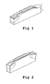
- Inserts for parting and grooving have an elongated shape. They can have a cutting edge in only one end, Fig 1 , or in both ends, Fig 2 . They are single sided with a rake face with chip breakers to ensure effective chip removal particularly in parting operations where the space is often restricted.
- the bottom surface generally has a shape to ensure good stability of the insert in the holder. Generally, the bottom surface is slightly concave to ensure that the inserts essentially are in contact with the insert seat of the holder at its both ends.
- Inserts for parting and grooving generally have a length of more than 15 mm and up to 35 mm, a width of 1-12 mm and a height of 5-10 mm. They are generally provided with coatings deposited by CVD, MTCVD or PVD as known in the art.
- US 5,477,754 discloses a metal cutting insert made by sintering an insert body and coating the sintered insert body with a conventional coating. Subsequently, a supporting surface of the insert is ground smooth while removing the coating therefrom. The supporting surface of the insert is thereby formed by an uncoated, smoothly ground surface.
- EP 1864731 A1 discloses an indexable insert wherein the residual stress in a coating on the rake face is lower than the residual stress in the bearing surface.
- EP 1862240 A1 discloses an indexable insert wherein the coating on a seating face is removed completely or originally not formed thereon.
- Fig 1 shows a parting and grooving insert with one cutting edge
- Fig 2 shows a parting and grooving insert with two cutting edges.
- the present invention relates to a cutting tool insert with an elongated shape with a rake face and an opposite bottom surface, both with a coating, the insert has a length, L, width, W, and height, H, all in mm, such that L>W+H and the bottom surface of the insert is blasted.
- the cutting tool insert is particularly suitable for parting and grooving.
- the room temperature hardness of the cutting tool insert is suitably >1500 HV3.
- the length L is measured along the bottom surface, W and H in the middle of the insert. Both the rake face and the blasted bottom surface have a coating.
- the coating of the bottom surface has suitably a residual stress P(b) being less than the residual stress in the coating on the rake face P(r).
- the residual stress in the coating of the bottom surface is compressive, i.e. P(b) ⁇ 0.
- the bottom side of the insert suitably has a concave shape so that the gap occurring between the bottom surface and a flat surface on which the inserts rests, measured at the middle of the insert, is > 0.01 mm, but ⁇ 0.1 mm, preferably ⁇ 0.05 mm.
- the insert is preferably provided with a CVD and/or an MTCVD coating.
- the total thickness of the coating on non-blasted coated areas is suitably >4 ⁇ m, preferably >8 ⁇ m.
- the rake face can be blasted for improved performance.
- the blasted bottom surface preferably has a remaining coating with a total thickness of preferably > 1 ⁇ m, most preferably > 3 ⁇ m.
- the invention also relates to a method of making a cutting tool insert with a coating and having an elongated shape with a rake face and an opposite bottom surface, wherein the bottom surface is blasted and the insert has a length, L, width, W, and height, H, all in mm, such that L>W+H.
- the length L is measured along the bottom surface, W and H in the middle of the insert.
- the insert is provided with a CVD and/or an MTCVD coating.
- the total thickness of the coating on non-blasted coated areas is suitably >4 ⁇ m, preferably >8 ⁇ m.
- the bottom surface of the inserts are after the coating subjected to a blasting operation, preferably wet blasting.
- a blasting operation preferably wet blasting.
- the rake face is also subjected to a blasting operation.
- the blasting is made with a slurry comprising Al 2 O 3 in water.
- the blasting operation is made with a slurry comprising F150 grits (FEPA-standard) of Al 2 O 3 in water at an air pressure of 2.2-2.6 bar for about 10-20 sec/insert.
- the spray guns are placed about 100 mm from the inserts with a 90° spray angle.
- the coating of the bottom surface preferably remains to a significant extent after the blasting operation, so that the total coating thickness after the blasting operation is preferably > 1 ⁇ m, most preferably > 3 ⁇ m.
- the insert is particularly suitable for parting and grooving.
- the invention also relates to use of the cutting tool insert according to the invention for parting and grooving operations.
- the wet blasting operation was performed with a slurry consisting of F150 grits (FEPA-standard) of Al 2 O 3 in water at an air pressure of 2.4 bar for about 15 sec/insert.
- the spray guns were placed about 100 mm from the inserts with a 90° spray angle.
- Example 1 was repeated with 10 inserts N123J2-0600-RO with a composition of 6 wt-% Co and rest WC with an average grain size of about 1 ⁇ m and a hardness at room temperature of 1750 HV3 with a length of 25 mm, a width of 4 mm and a thickness of 6 mm and a coating consisting of 2.5 ⁇ m MTCVD-Ti(C,N)+ 1.5 ⁇ m Al 2 O 3 + 0.5 ⁇ m TiN.
Landscapes
- Chemical & Material Sciences (AREA)
- Engineering & Computer Science (AREA)
- Mechanical Engineering (AREA)
- Chemical Kinetics & Catalysis (AREA)
- Materials Engineering (AREA)
- Metallurgy (AREA)
- Organic Chemistry (AREA)
- General Chemical & Material Sciences (AREA)
- Cutting Tools, Boring Holders, And Turrets (AREA)
- Chemical Vapour Deposition (AREA)
Applications Claiming Priority (1)
| Application Number | Priority Date | Filing Date | Title |
|---|---|---|---|
| SE0702232A SE0702232L (sv) | 2007-10-05 | 2007-10-05 | Skär för avstickning eller spårstickning och tillverkningssätt |
Publications (1)
| Publication Number | Publication Date |
|---|---|
| EP2060347A1 true EP2060347A1 (fr) | 2009-05-20 |
Family
ID=40467320
Family Applications (1)
| Application Number | Title | Priority Date | Filing Date |
|---|---|---|---|
| EP08446508A Withdrawn EP2060347A1 (fr) | 2007-10-05 | 2008-09-11 | Inserts pour séparer ou rainurer et leurs procédés de fabrication |
Country Status (6)
| Country | Link |
|---|---|
| US (1) | US20090092453A1 (fr) |
| EP (1) | EP2060347A1 (fr) |
| JP (1) | JP5203877B2 (fr) |
| KR (1) | KR101521299B1 (fr) |
| CN (1) | CN101480728B (fr) |
| SE (1) | SE0702232L (fr) |
Families Citing this family (6)
| Publication number | Priority date | Publication date | Assignee | Title |
|---|---|---|---|---|
| USD616003S1 (en) * | 2009-02-02 | 2010-05-18 | Sumitomo Electric Hardmetal Corp. | Indexable insert for a grooving tool |
| JP5698833B2 (ja) * | 2011-02-28 | 2015-04-08 | 京セラ株式会社 | 切削インサートおよび切削工具、並びにそれらを用いた切削加工物の製造方法 |
| JP5279099B1 (ja) | 2012-03-14 | 2013-09-04 | 住友電工ハードメタル株式会社 | 切削工具 |
| EP3023178B1 (fr) * | 2014-11-24 | 2022-05-11 | Sandvik Intellectual Property AB | Procédé de meulage d'un insert de rainurage/séparation et insert de rainurage/séparation |
| US12465981B2 (en) * | 2022-09-07 | 2025-11-11 | Iscar, Ltd. | Cemented carbide cutting insert for parting metal workpieces |
| CN119566749B (zh) * | 2024-12-27 | 2025-09-23 | 马鞍山市恒利达机械刀片有限公司 | 一种纸箱开槽刀生产工艺 |
Citations (5)
| Publication number | Priority date | Publication date | Assignee | Title |
|---|---|---|---|---|
| US5477754A (en) | 1993-08-30 | 1995-12-26 | Carboloy Inc. | Metal cutting inserts and method of making |
| EP0775544A1 (fr) * | 1995-11-23 | 1997-05-28 | Sandvik Aktiebolag | Plaquette de coupe pour le rainurage et pour l'élargissement des rainures |
| WO2006103899A1 (fr) * | 2005-03-25 | 2006-10-05 | Sumitomo Electric Hardmetal Corp. | Pointe de remplacement de bord de coupeur |
| WO2006112221A1 (fr) * | 2005-03-30 | 2006-10-26 | Sumitomo Electric Hardmetal Corp. | Pointe de cutter de remplacement de bord |
| EP1793014A1 (fr) | 2005-12-02 | 2007-06-06 | Mitsubishi Materials Corporation | Plaquette de coupe revêtue et procédé pour sa fabrication |
Family Cites Families (10)
| Publication number | Priority date | Publication date | Assignee | Title |
|---|---|---|---|---|
| SE466689B (sv) * | 1990-07-19 | 1992-03-23 | Sandvik Ab | Skaer foer profil- och spaarsvarvning |
| SE500722C2 (sv) * | 1993-01-27 | 1994-08-15 | Sandvik Ab | Skär med vriden spånyta |
| US5511911A (en) * | 1994-07-05 | 1996-04-30 | Valenite Inc. | Cutting insert |
| SE512094C2 (sv) * | 1998-05-22 | 2000-01-24 | Sandvik Ab | Skär för spårstickning |
| SE514872C2 (sv) * | 1998-09-09 | 2001-05-07 | Sandvik Ab | Skär för spårsvarvning |
| SE526110C2 (sv) * | 2002-06-25 | 2005-07-05 | Seco Tools Ab | Skär för spånavskiljande bearbetning med negativ grundform där släppningsytan ansluter till spånbrytaren |
| US7455918B2 (en) * | 2004-03-12 | 2008-11-25 | Kennametal Inc. | Alumina coating, coated product and method of making the same |
| SE528696C2 (sv) * | 2005-02-25 | 2007-01-23 | Sandvik Intellectual Property | CVD-belagt skär av hårdmetall, cermet eller keramik och sätt att tillverka detsamma |
| JP2006326755A (ja) * | 2005-05-26 | 2006-12-07 | Kyocera Corp | スローアウェイチップおよびそれを備える転削用工具 |
| US7665933B2 (en) * | 2007-03-30 | 2010-02-23 | Mitsubishi Materials Corporation | Cutting insert |
-
2007
- 2007-10-05 SE SE0702232A patent/SE0702232L/xx not_active Application Discontinuation
-
2008
- 2008-09-11 EP EP08446508A patent/EP2060347A1/fr not_active Withdrawn
- 2008-10-02 KR KR1020080097067A patent/KR101521299B1/ko not_active Expired - Fee Related
- 2008-10-03 US US12/245,323 patent/US20090092453A1/en not_active Abandoned
- 2008-10-03 JP JP2008258955A patent/JP5203877B2/ja not_active Expired - Fee Related
- 2008-10-06 CN CN200810168977.9A patent/CN101480728B/zh not_active Expired - Fee Related
Patent Citations (7)
| Publication number | Priority date | Publication date | Assignee | Title |
|---|---|---|---|---|
| US5477754A (en) | 1993-08-30 | 1995-12-26 | Carboloy Inc. | Metal cutting inserts and method of making |
| EP0775544A1 (fr) * | 1995-11-23 | 1997-05-28 | Sandvik Aktiebolag | Plaquette de coupe pour le rainurage et pour l'élargissement des rainures |
| WO2006103899A1 (fr) * | 2005-03-25 | 2006-10-05 | Sumitomo Electric Hardmetal Corp. | Pointe de remplacement de bord de coupeur |
| EP1862240A1 (fr) * | 2005-03-25 | 2007-12-05 | Sumitomo Electric Hardmetal Corp. | Pointe de remplacement de bord de coupeur |
| WO2006112221A1 (fr) * | 2005-03-30 | 2006-10-26 | Sumitomo Electric Hardmetal Corp. | Pointe de cutter de remplacement de bord |
| EP1864731A1 (fr) | 2005-03-30 | 2007-12-12 | Sumitomo Electric Hardmetal Corp. | Pointe de cutter de remplacement de bord |
| EP1793014A1 (fr) | 2005-12-02 | 2007-06-06 | Mitsubishi Materials Corporation | Plaquette de coupe revêtue et procédé pour sa fabrication |
Also Published As
| Publication number | Publication date |
|---|---|
| SE0702232L (sv) | 2009-04-06 |
| JP5203877B2 (ja) | 2013-06-05 |
| JP2009090459A (ja) | 2009-04-30 |
| CN101480728B (zh) | 2015-07-08 |
| KR101521299B1 (ko) | 2015-05-18 |
| KR20090035445A (ko) | 2009-04-09 |
| US20090092453A1 (en) | 2009-04-09 |
| CN101480728A (zh) | 2009-07-15 |
Similar Documents
| Publication | Publication Date | Title |
|---|---|---|
| EP2060347A1 (fr) | Inserts pour séparer ou rainurer et leurs procédés de fabrication | |
| EP1893786B1 (fr) | Procede de fabrication d'outils de coupe pour metaux | |
| EP3392379B1 (fr) | Outil de coupe recouvert avec une couche en alpha-alumina | |
| EP2425028B1 (fr) | Outils en carbure cémenté | |
| EP3369831A1 (fr) | Comprimé frité et son procédé de production | |
| EP2484807B1 (fr) | Outil de découpe à revêtement de surface doté d'une couche de revêtement en dur ayant une excellente résistance à la fragmentation et résistance à la fracturation | |
| EP3603857A1 (fr) | Outil de coupe de carbure cémenté à revêtement de diamant | |
| EP2036997A1 (fr) | Inserts d'outils de découpe à carbure cimentée revêtue | |
| EP3392380B1 (fr) | Outil de coupe revêtu | |
| EP1741505B1 (fr) | Outil de compact fritté de nitrure de bore cubique revêtu superficiellement et procédé de fabrication dudit outil | |
| EP2826578B1 (fr) | Outil de coupe | |
| KR101757489B1 (ko) | 내칩핑성이 우수한 표면 피복 절삭 공구 | |
| EP3067133A9 (fr) | Outil de coupe plaqué | |
| EP3456858B1 (fr) | Outil de coupe recouvert | |
| EP3498406B1 (fr) | Outil de coupe revêtu en surface à excellente résistance à l'écaillage et au décollage induits par l'adhérence | |
| EP3437772A1 (fr) | Outil de coupe revêtu en surface | |
| KR101802161B1 (ko) | 볼 엔드밀 및 그 제조 방법 | |
| EP3199276A1 (fr) | Outil de coupe à corps fritté composite | |
| JP5062541B2 (ja) | 刃先交換型切削工具 | |
| JP2003155538A (ja) | 超硬合金 | |
| JP2011218481A (ja) | 炭窒化チタン基サーメット製切削インサートおよびその製造方法 | |
| EP4098770A1 (fr) | Outil de coupe revêtu | |
| KR20170054768A (ko) | 단조강용 절삭공구 인써트 | |
| JPH07197265A (ja) | 表面被覆高強度超硬合金 | |
| CN116348227A (zh) | 金属陶瓷制刀片以及具备其的切削刀具 |
Legal Events
| Date | Code | Title | Description |
|---|---|---|---|
| PUAI | Public reference made under article 153(3) epc to a published international application that has entered the european phase |
Free format text: ORIGINAL CODE: 0009012 |
|
| 17P | Request for examination filed |
Effective date: 20080911 |
|
| AK | Designated contracting states |
Kind code of ref document: A1 Designated state(s): AT BE BG CH CY CZ DE DK EE ES FI FR GB GR HR HU IE IS IT LI LT LU LV MC MT NL NO PL PT RO SE SI SK TR |
|
| AX | Request for extension of the european patent |
Extension state: AL BA MK RS |
|
| 17Q | First examination report despatched |
Effective date: 20090625 |
|
| AKX | Designation fees paid |
Designated state(s): AT BE BG CH CY CZ DE DK EE ES FI FR GB GR HR HU IE IS IT LI LT LU LV MC MT NL NO PL PT RO SE SI SK TR |
|
| GRAP | Despatch of communication of intention to grant a patent |
Free format text: ORIGINAL CODE: EPIDOSNIGR1 |
|
| INTG | Intention to grant announced |
Effective date: 20191011 |
|
| STAA | Information on the status of an ep patent application or granted ep patent |
Free format text: STATUS: THE APPLICATION IS DEEMED TO BE WITHDRAWN |
|
| 18D | Application deemed to be withdrawn |
Effective date: 20200222 |