EP2060355A2 - Stone saw blade - Google Patents
Stone saw blade Download PDFInfo
- Publication number
- EP2060355A2 EP2060355A2 EP08167962A EP08167962A EP2060355A2 EP 2060355 A2 EP2060355 A2 EP 2060355A2 EP 08167962 A EP08167962 A EP 08167962A EP 08167962 A EP08167962 A EP 08167962A EP 2060355 A2 EP2060355 A2 EP 2060355A2
- Authority
- EP
- European Patent Office
- Prior art keywords
- saw blade
- teeth
- layer
- shaped
- blade according
- Prior art date
- Legal status (The legal status is an assumption and is not a legal conclusion. Google has not performed a legal analysis and makes no representation as to the accuracy of the status listed.)
- Granted
Links
Images


Classifications
-
- B—PERFORMING OPERATIONS; TRANSPORTING
- B28—WORKING CEMENT, CLAY, OR STONE
- B28D—WORKING STONE OR STONE-LIKE MATERIALS
- B28D1/00—Working stone or stone-like materials, e.g. brick, concrete or glass, not provided for elsewhere; Machines, devices, tools therefor
- B28D1/02—Working stone or stone-like materials, e.g. brick, concrete or glass, not provided for elsewhere; Machines, devices, tools therefor by sawing
- B28D1/12—Saw-blades or saw-discs specially adapted for working stone
- B28D1/127—Straight, i.e. flat, saw blades; strap saw blades
Definitions
- the invention relates to a saw blade with a band-shaped base body and unrestricted teeth with geometrically determined cutting edges, the teeth having molded bodies made of hard metal connected to the base body.
- the saw blade has a band-shaped body, so it is designed as a saw blade.
- the band-shaped base body has seats which are intended to receive shaped bodies made of hard metal. In general, these seats are made by milling the band-shaped body.
- the shaped bodies made of hard metal are produced as separate elements and permanently connected via the seats with the band-shaped base body.
- the shaped bodies of hard metal have geometrically determined cutting edges and thus form the teeth of the saw blade.
- a saw blade is from the German patent application DE 42 00 423 A1 known.
- the saw blade is designed and intended for machining metallic materials. It has a base body with unrestricted teeth with cutting edges, which are provided in repetitive cycles.
- the teeth may consist of the moldings connected to the body made of hard metal.
- Each cycle consists of at least one tooth group consisting of at least three teeth with height and width graduation.
- the teeth may be from tooth to tooth decreasing height and thereby increasing width. All teeth are formed symmetrically to a longitudinal center plane through the body.
- the teeth have geometrically determined cutting edges, ie each tooth has a geometrically determined shape with rake angle, clearance angle, etc.
- the effective cutting or cutting portions of all teeth are each formed by a kinking cutting edge whose inner portion is approximately perpendicular to the longitudinal center plane and connect to the outwardly in a symmetrical arrangement to the base towards inclined chamfers.
- the cutting edge thus has corners both in the region of the kinking cutting edge and at the transition between chamfer and flank.
- the cutting edges on each tooth can be changed in shape by increasing the number of breakpoints.
- the number of teeth in the cycle is at least 2.
- the teeth may consist of the moldings connected to the body made of hard metal.
- the two teeth have a height and a width grading and form a first group of teeth.
- an effective cutting edge is formed in the form of a kinking line.
- the teeth of the second group of teeth are identical.
- the teeth of the second group of teeth represent the teeth with the largest width and the lowest height.
- the teeth of the first group of teeth and the second group of teeth can be arranged alternately.
- the invention has for its object to provide a saw blade, which provides a high cutting performance without large loss of material, flexible for the production of workpieces with different dimensions and is suitable for sawing stone.
- the shaped articles for sawing stone thus have a support made of hard metal and a layer forming the cutting edge, wherein the layer has a hardness of at least 5,000 HK.
- wire saws are known in which a circulating cable is used, which is covered with cylindrical segments, wherein the segments are coated with diamond.
- Such wire saws provide a low cutting performance, can be used only with relatively low feed and work in stone a relatively wide cutting channel, so that in such a separation work, a relatively large loss of material occurs.
- the producible cuts are rarely straight and provide a relatively large roughness on the cut surface.
- horizontal sawing saws are used for sawing stone, which are designed and arranged in their basic structure in itself, as is known in gate saws for wood.
- the saw blades are diamond-strewn, so there are no geometrically determined cutting edges.
- the disadvantage of such gang saws is determined by the low flexibility and the slice thickness predetermined by the setting.
- a tool for milling grooves and folds is from the European patent application EP 0 590 408 A1 known. This document thus shows and describes a milling cutter. An indication of the formation of a saw blade does not contain this document.
- a saw blade is from the European patent application EP 0 715 919 A1 known. This document shows a positive connection of the use of the saw blade via a clamping or plug connection with the base body.
- the inserts can have a surface hardness of at least 1200 HV 30.
- a drill is from the German patent application DE 196 52 208 A1 known. This document relates to a drill, in particular for drilling boreholes in hard material, such as Stone. An indication of the formation of a saw blade does not contain this document.
- the invention relates to a saw blade with a band-shaped base body and unrestricted teeth with geometrically determined cutting edges, the teeth having molded bodies made of hard metal connected to the base body.
- the shaped bodies have a hard metal carrier and a layer forming the cutting edge for sawing stone, the layer having a hardness of at least 5,000 HK. So it is a stone saw blade.
- the new layer is therefore substantially harder than the carrier of the shaped body of the hard metal.
- the shaped bodies form the teeth of the saw blade and have a geometrically determined shape with a cutting edge, cutting edge, rake angle, clearance angle, etc. It is sufficient if the layer on the shaped bodies made of hard metal is dimensioned comparatively thin. Important is the extremely high hardness, which is achieved only by a few materials.
- the layer may consist of polycrystalline diamond (PCD) or of cubic boron nitride (CBN). Such materials are not used in saw blades.
- the layer thus has a hardness of at least 5,000 HK (Knoop hardness, see also DIN EN ISO 4545), HK - HV (Vickers hardness) being valid for small loads.
- the layer may be provided on the surface of the carrier of the molded body facing forwards in the direction of travel of the strip.
- the layer forms a rake surface with which the material to be removed and the removed material at least partially come into contact. This includes the cutting edge of the rake face.
- Bending cutting edges are therefore preferably not used and corners or sharp Abknickabil in the cutting edge are omitted. This may relate in particular to the transition between the cutting edge and the back surface but also to the transition to the flank surfaces of the tooth.
- the round shape avoids corners. It has a rounded shape, which can be formed from adjoining elbows, even with different radii. In a special form, the round cutting edge can be circular.
- the shaped body of the hard metal carrier and the layer of high hardness can be defined positively held on the band-shaped body in a milled seat defined. This refers at least to both the radial and the tangential direction.
- the permanent connection between the moldings made of hard metal and the band-shaped body can be done by common types of connection, such as welding, soldering and the like.
- the geometrically determined cutting edges for the new saw blade for cutting stone can in themselves have all the features and advantages of saw blades for cutting metallic materials from the patent applications DE 42 00 423 A1 and or DE 199 63 396 A1 the applicant are known.
- Each cycle should have at least one tooth group of at least three teeth, with a height grading and a width graduation, wherein the height gradation may decrease from tooth to tooth, and the tooth width may also increase from tooth to tooth.
- a plurality of tooth groups to be intermittently nested on one base body, but at least the teeth of one tooth group should have rounded cutting edges.
- Another group of teeth may also have rounded cutting edges, but only teeth of identical geometric shape in the group.
- the teeth formed by the shaped bodies can have a negative rake angle, in particular approximately between -25 ° and 0 °.
- the clearance angle can be 0 ° to 15 °.
- Such a clearance angle refers to the roof surface of a tooth and / or on the formation of the flanks.
- the teeth formed by the moldings have a positive rake angle, but then with a negative protective bevel of about 0 ° to -25 °. Also, it is advantageously achieved a hammering fragmentation of the rock material during sawing.
- the rake surface may have a hard material coating on the layer of each shaped body.
- Aluminum titanium nitride, titanium aluminum carbonitride, chromium nitride or the like are particularly suitable for this purpose.
- the coating can also be applied as a multilayer structure. It should usually extend over the rake face and also over the cutting edge and part of the flanks on each molding.
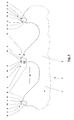
- This in Fig. 1 partially illustrated example new saw blade 1 has a band-shaped base body 2, which has a rectangular cross section in a known manner.
- the one side of the main body 2 shown carries teeth 3.
- the teeth 3 are unrestricted and preferably formed and arranged symmetrically to the longitudinal center plane 14 of the base body 2.
- the teeth 3 have a greater width than the main body. 2
- the teeth 3 are formed or formed by shaped bodies 4.
- Each shaped body 4 consists for the most part of a carrier 21 made of hard metal and has on one side or surface a layer 5 which consists of a material which is harder than the hard metal of the carrier 21 of the shaped body 4.
- the hardness of the layer 5, which is permanently bonded to the hard metal of the carrier 21 of the molded body 4, is at least 5,000 HK (Knoop hardness, see DIN EN ISO 4545). Suitable materials which exhibit such exceptional hardness are in particular polycrystalline diamond (PCD) or cubic boron nitride (CBN).
- the moldings 4 with the layers 5 are inserted into seats 6.
- the moldings 4 are permanently connected to the seats 6 with the material of the base body 2, for example by welding or soldering.
- the seats 6 are shaped so that each shaped body 4 is placed and held positively in two directions extending at least approximately at right angles to each other.
- the placement of the molded body 4 is carried out so that the layers 5 point in the direction of tape travel 7.
- Fig. 1 It can be seen that the shaped bodies 4, which form the teeth 3, are arranged with a negative rake angle 8.
- the rake angle 8 of all teeth 3 may be formed coincident. But it is also possible that the negative rake angle 8 vary from tooth 3 to tooth 3, so that in this way groups of teeth from z. B. three consecutive teeth 3 are formed, with the negative rake angle repeat 8 at the respective teeth 3 in each group. Negative rake angles 8, in particular between -25 ° and 0 °, are used.
- the teeth 3 can also be arranged with variable pitch.
- the teeth 3 can also be arranged in a height and / or a width graduation.
- Each tooth 3 has on the running in the direction of tape 7 forward facing free surface of the layer 5, a clamping surface 9, which merges at its upper portion in a cutting edge 10 and ends in this cutting edge 10.
- the upper portions of the rake surface 9 and the cutting edge 10 together form a respective cutting edge 11.
- the forming the teeth 3 moldings 4 are arranged with a clearance angle 12, so that there is a back rake surface on each tooth 3.
- Fig. 2 shows the relative design of three teeth 3 in their mutual projection against the tape running direction 7 in the region of the cutting 11. It is a tooth 3 1 recognizable, the counter to the strip running direction 7, a second tooth 3 2 follows, in turn, from a tooth 3 3 opposite the tape running direction 7 is followed. It can be seen that a group of teeth is preferably formed from at least three teeth 3 1 , 3 2 , 3 3 . This group is repeated in cycles. Each cycle has at least one group, ie three consecutive teeth 3. However, other forms of teeth 3, groups and cycles are possible.
- the tooth 3 1 has a rake surface 9 1 , which merges at its upper end into a cutting edge 10 1 .
- the cutting edge 10 is formed and arranged in a circular arc and goes to form each corner on the right and left in each case a flank 13 via.
- the flanks 13 and the associated flank angles coincide on all teeth 3 1 , 3 2 and 3 3 and coincide in the projection.
- the following tooth 3 2 has a cutting edge 10 2 .
- the shaping reveals that the cutting edge 10 2 is composed of a series of radii so that overall the rounded shape shown results.
- the cutting edge 10 2 In the central region, that is, following the longitudinal center plane 14, the cutting edge 10 2 has a straight piece 15 2 , in which the radius is therefore infinitely large.
- a respective elbow 16 2 At this straight piece 15 2 is followed by a respective elbow 16 2 , which has a finite radius.
- Each elbow 16 2 finally goes into another elbow 17 2 over.
- the transition between the elbows 16 2 and 17 2 is preferably carried out with a common tangent.
- the elbow 17 2 runs into the flank 13 almost without a break point.
- the third tooth 3 3 in the tooth group has a rounded cutting edge 10 3rd
- the cutting edge 10 3 is also composed here of a straight piece 15 3 and two elbows 16 3 and 17 3 together.
- the elbow 17 3 is arranged and is determined by a radius selected so that it enters tangentially into the flank 13.
- the transition point is slightly below the point at which the tooth 3 3 has its greatest width.
- At least one of the teeth 3 1 , 3 2 and 3 3 has such a shape as described with reference to the tooth 3 3 .
- Fig. 2 is also a height and width gradation of the teeth 3 1 , 3 2 and 3 3 recognizable.
- the tooth 3 1 is the tooth with the largest height and smallest width.
- the tooth 3 3 is the tooth with the lowest height and largest width.
- the tooth 3 2 lies in between.
- the order of the teeth 3 1 , 3 2 and 3 3 in the direction of belt 7 is not mandatory.
- the teeth 3 1 , 3 2 and 3 3 3 may have the same or different rake angle 8.
- the clearance angle 12 at the back of the teeth can also vary.
- Each tooth 3 1 , 3 2 and 3 3 3 preferably operates only with the region of its cutting edge 10, in accordance with the projection Fig. 2 survives freely. In this way, strips of material are eliminated in the cutting channel, as is already the case in the prior art described above. The clearing out of the material strips However, it does not spanwise, but more by hammering material fragmentation by the individual strip-shaped areas of the rock material are smashed and smashed in the cutting
- the molded body 4 has the carrier 21 made of hard metal, which carries on one side the layer 5 of PCD or CBN.
- the layer 5 is thinner, generally substantially thinner, than the carrier 21 of the shaped body 4.
- the shaped body 4 forms with the free surface of the layer 5, the rake face 9, which merges at its upper end in the cutting edge 10, which, as Fig. 4 shows, is formed here arcuate.
- the molded body 4 has a recess 18 and a channel whose width corresponds to the thickness of the band-shaped base body 2. Taking into account the design and arrangement of the seats 6 in conjunction with the recess 18 is thus recognizable that each shaped body 4 is defined in all three spatial directions positively secured to the base body 2.
- Fig. 5 shows a further embodiment of the saw blade 1 with its base body 2 and three teeth 3 1 , 3 2 and 3 3 in the teeth group. It is understood that the number of teeth 3 in the group of teeth may also be greater or less than three.
- the teeth 3 1 , 3 2 and 3 3 are arranged here with a positive rake angle 19.
- the rake angle 19 of the individual teeth 3 1 , 3 2 and 3 3 can be designed to match or even varying. The same applies to the division.
- the protective bevel 20 extends within the layer 5.
- the protective bevel 20 also results in a negative angle in the region of the cutting edge 10, so that even with this embodiment, the intended hammering and shattering effect of the cutting 11 on the rock material is also possible.
- Areas of the rake surface 9 and / or the protective bevel 20 including the cutting edge 10 of the layer 5 may be provided with a hard coating 22. This is for clarity only on the tooth 3 3 in Fig. 5 shown.
- the hard material coating 22 may also extend over part of the flanks 13 of the teeth 3.
- the hard material coating 22 may in particular consist of aluminum titanium nitride, titanium aluminum carbonitride or chromium nitride.
Landscapes
- Engineering & Computer Science (AREA)
- Mining & Mineral Resources (AREA)
- Mechanical Engineering (AREA)
- Processing Of Stones Or Stones Resemblance Materials (AREA)
Abstract
Ein Sägeblatt (1) zum Sägen von Stein weist einen bandförmigen Grundkörper (2) und ungeschränkte Zähne (3) mit geometrisch bestimmten Schneiden (11) auf, wobei die Zähne (3) mit dem Grundkörper (2) verbundene Formkörper (4) aus Hartmetall aufweisen. Die Formkörper (4) weisen zum Sägen von Stein einen Träger (21) aus Hartmetall und eine die Schneide (11) bildende Schicht (5) auf, wobei die Schicht (5) eine Härte von mindestens 5.000 HK besitzt.A saw blade (1) for sawing stone has a band-shaped basic body (2) and unrestricted teeth (3) with geometrically determined cutting edges (11), wherein the teeth (3) are bonded to the basic body (2) shaped bodies (4) made of hard metal exhibit. The shaped bodies (4) have a carrier (21) made of hard metal for sawing stone and a layer (5) forming the cutting edge (11), wherein the layer (5) has a hardness of at least 5,000 HK.
Description
Die Erfindung betrifft ein Sägeblatt mit einem bandförmigen Grundkörper und ungeschränkten Zähnen mit geometrisch bestimmten Schneiden, wobei die Zähne mit dem Grundkörper verbundene Formkörper aus Hartmetall aufweisen.The invention relates to a saw blade with a band-shaped base body and unrestricted teeth with geometrically determined cutting edges, the teeth having molded bodies made of hard metal connected to the base body.
Das Sägeblatt besitzt einen bandförmigen Grundkörper, ist also als Sägeband ausgebildet. Der bandförmige Grundkörper besitzt Sitze, die zur Aufnahme von Formkörpern aus Hartmetall bestimmt sind. In der Regel werden diese Sitze durch Fräsen des bandförmigen Grundkörpers hergestellt. Die Formkörper aus Hartmetall werden als separate Elemente hergestellt und über die Sitze dauerhaft mit dem bandförmigen Grundkörper verbunden. Die Formkörper aus Hartmetall besitzen geometrisch bestimmte Schneiden und bilden damit die Zähne des Sägeblatts.The saw blade has a band-shaped body, so it is designed as a saw blade. The band-shaped base body has seats which are intended to receive shaped bodies made of hard metal. In general, these seats are made by milling the band-shaped body. The shaped bodies made of hard metal are produced as separate elements and permanently connected via the seats with the band-shaped base body. The shaped bodies of hard metal have geometrically determined cutting edges and thus form the teeth of the saw blade.
Ein Sägeblatt ist aus der deutschen Patentanmeldung
Ein weiteres Sägeblatt ist auch aus der deutschen Patentanmeldung
Der Erfindung liegt die Aufgabe zugrunde, ein Sägeblatt bereitzustellen, welches eine hohe Zerspanungsleistung ohne großen Materialverlust erbringt, zur Erzeugung von Werkstücken mit unterschiedlichen Abmessungen flexibel einsetzbar und zum Sägen von Stein geeignet ist.The invention has for its object to provide a saw blade, which provides a high cutting performance without large loss of material, flexible for the production of workpieces with different dimensions and is suitable for sawing stone.
Erfindungsgemäß wird die Aufgabe durch ein Sägeblatt mit den Merkmalen des Patentanspruchs 1 gelöst.According to the invention, the object is achieved by a saw blade having the features of
Die Formkörper zum Sägen von Stein weisen also einen Träger aus Hartmetall und eine die Schneide bildende Schicht auf, wobei die Schicht eine Härte von mindestens 5.000 HK besitzt.The shaped articles for sawing stone thus have a support made of hard metal and a layer forming the cutting edge, wherein the layer has a hardness of at least 5,000 HK.
Es ist auch allgemein bekannt, dass zum Trennen von Stein, insbesondere Granit, Sandstein, Marmor und dergleichen, auch Sägeelemente eingesetzt werden, die keine geometrisch bestimmten Schneiden aufweisen. So sind beispielsweise Seilsägen bekannt, bei denen ein umlaufendes Seil eingesetzt wird, welches mit zylinderförmigen Segmenten besetzt ist, wobei die Segmente mit Diamant beschichtet sind. Solche Seilsägen erbringen eine geringe Schnittleistung, können nur mit vergleichsweise geringem Vorschub eingesetzt werden und arbeiten im Stein einen relativ breiten Schnittkanal aus, so dass bei einer solchen Trennarbeit ein relativ großer Materialverlust eintritt. Die erzeugbaren Schnitte sind selten gerade und erbringen an der Schnittfläche eine relativ große Rautiefe.It is also well known that for the separation of stone, in particular granite, sandstone, marble and the like, and sawing elements are used which have no geometrically determined cutting. For example, wire saws are known in which a circulating cable is used, which is covered with cylindrical segments, wherein the segments are coated with diamond. Such wire saws provide a low cutting performance, can be used only with relatively low feed and work in stone a relatively wide cutting channel, so that in such a separation work, a relatively large loss of material occurs. The producible cuts are rarely straight and provide a relatively large roughness on the cut surface.
Es ist weiterhin allgemein bekannt, dass zum Trennen von Stein auch Trennscheiben mit relativ großem Durchmesser eingesetzt werden, die zwar vorteilhaft eine hohe Schnittleistung erbringen, jedoch nachteilig einen entsprechend breiten Schnittkanal im Stein ausarbeiten.It is also well known that for separating stone and cutting discs are used with a relatively large diameter, which advantageously provide a high cutting performance, but disadvantageously work out a correspondingly wide cutting channel in the stone.
Es ist auch allgemein bekannt, dass zum Sägen von Stein horizontale Gattersägen eingesetzt werden, die in ihrem grundsätzlichen Aufbau an sich so ausgebildet und angeordnet sind, wie dies bei Gattersägen für Holz bekannt ist. Die Sägeblätter sind hier jedoch diamantbestreut, so dass keine geometrisch bestimmten Schneiden vorliegen. Der Nachteil solcher Gattersägen ist in der geringen Flexibilität und der durch die Einstellung vorgegebenen Scheibendicke festgelegt.It is also well known that horizontal sawing saws are used for sawing stone, which are designed and arranged in their basic structure in itself, as is known in gate saws for wood. However, the saw blades are diamond-strewn, so there are no geometrically determined cutting edges. The disadvantage of such gang saws is determined by the low flexibility and the slice thickness predetermined by the setting.
Ein Werkzeug zum Fräsen von Nuten und Falzen ist aus der europäischen Patentanmeldung
Ein Sägeblatt ist aus der europäischen Patentanmeldung
Ein Bohrer ist aus der deutschen Patentanmeldung
Die Erfindung betrifft ein Sägeblatt mit einem bandförmigen Grundkörper und ungeschränkten Zähnen mit geometrisch bestimmten Schneiden, wobei die Zähne mit dem Grundkörper verbundene Formkörper aus Hartmetall aufweisen. Die Formkörper weisen zum Sägen von Stein einen Träger aus Hartmetall und eine die Schneide bildende Schicht auf, wobei die Schicht eine Härte von mindestens 5.000 HK besitzt. Es handelt sich also um ein Steinsägeblatt.The invention relates to a saw blade with a band-shaped base body and unrestricted teeth with geometrically determined cutting edges, the teeth having molded bodies made of hard metal connected to the base body. The shaped bodies have a hard metal carrier and a layer forming the cutting edge for sawing stone, the layer having a hardness of at least 5,000 HK. So it is a stone saw blade.
Unter spanend arbeitenden Trennverfahren mit einer Schneide mit geometrisch bestimmter Schneidenform sind dabei in dieser Anmeldung im Sinne der DIN 8580 Drehen, Bohren, Fräsen, Hobeln, Räumen, Sägen und Feilen zu verstehen. Als spanend arbeitende Trennverfahren mit einer Schneide mit geometrisch unbestimmter Schneidenform sind u. a. Schleifen, Honen und Läppen anzusehen.Under cutting working separation process with a cutting edge with geometrically defined cutting shape are in this application within the meaning of DIN 8580 turning, drilling, milling, planing, broaching, sawing and filing to understand. As a cutting working separation process with a cutting edge with geometrically indefinite cutting edge u. a. To look at grinding, honing and lapping.
Die neue Schicht ist also wesentlich härter als der Träger des Formkörpers aus dem Hartmetall. Die Formkörper bilden die Zähne des Sägeblatts und besitzen eine geometrisch bestimmte Form mit Schneide, Schneidkante, Spanwinkel, Freiwinkel, usw. Es reicht aus, wenn die Schicht auf den Formkörpern aus Hartmetall vergleichsweise dünn bemessen ist. Wichtig ist die extrem hohe Härte, die nur von wenigen Werkstoffen erreicht wird. Die Schicht kann insbesondere aus polykristallinem Diamant (PKD) oder auch aus kubischem Bornitrid (CBN) bestehen. Derartige Materialien werden bisher bei Sägeblättern nicht eingesetzt. Die Schicht besitzt also eine Härte von mindestens 5.000 HK (Knoophärte; vgl. auch DIN EN ISO 4545), wobei für kleine Lasten HK - HV (Vickershärte) gilt.The new layer is therefore substantially harder than the carrier of the shaped body of the hard metal. The shaped bodies form the teeth of the saw blade and have a geometrically determined shape with a cutting edge, cutting edge, rake angle, clearance angle, etc. It is sufficient if the layer on the shaped bodies made of hard metal is dimensioned comparatively thin. Important is the extremely high hardness, which is achieved only by a few materials. In particular, the layer may consist of polycrystalline diamond (PCD) or of cubic boron nitride (CBN). Such materials are not used in saw blades. The layer thus has a hardness of at least 5,000 HK (Knoop hardness, see also DIN EN ISO 4545), HK - HV (Vickers hardness) being valid for small loads.
Die Schicht kann auf der in Bandlaufrichtung nach vorn weisenden Fläche des Trägers des Formkörpers vorgesehen sein. Die Schicht bildet eine Spanfläche, mit der das abzutragende und das abgetragene Material zumindest teilweise in Verbindung kommen. Dies schließt die Schneidkante der Spanfläche mit ein. Der Einsatz dieser Schicht mit extrem großer Härte führt in Verbindung mit der Ausbildung des Trägers beim Sägen von Stein dazu, dass nicht so sehr eine schneidende Abnahme von Spänen eintritt, sondern eher ein Schlag- oder Hämmereffekt, bei dem kleinste Bereiche des Steins zertrümmert und insoweit abgetragen werden. Die Schicht schützt dabei den Träger des Formkörpers und damit den Zahn vor Verschleiß.The layer may be provided on the surface of the carrier of the molded body facing forwards in the direction of travel of the strip. The layer forms a rake surface with which the material to be removed and the removed material at least partially come into contact. This includes the cutting edge of the rake face. The use of this layer of extremely high hardness, in conjunction with the formation of the carrier when sawing stone, results in not so much a cutting decrease of chips but rather a hammering or hammering effect. at the smallest areas of the stone smashed and so far removed. The layer protects the wearer of the molding and thus the tooth from wear.
Vorteilhaft weist zumindest der mit dem Stein in Kontakt kommende Teil der Spanfläche der Schicht in Ansicht an mindestens einem Zahn einer Zahngruppe, vorzugsweise an allen Zähnen des Sägeblattes, entgegen der Bandlaufrichtung eine runde oder abgerundete Schneidkante auf. Abknickende Schneidkanten, wie sie im Stand der Technik bekannt sind, werden somit vorzugsweise nicht eingesetzt und Ecken oder spitze Abknickpunkte im Bereich der Schneidkante kommen in Fortfall. Dies kann sich insbesondere auf den Übergang zwischen Schneidkante und Rückenfreifläche aber auch auf den Übergang zu den Flankenflächen des Zahns beziehen. Die runde Form vermeidet Ecken. Sie weist eine abgerundete Gestalt auf, die aus aneinander anschließenden Bogenstücken, auch mit unterschiedlichen Radien, gebildet sein kann. In einer Sonderform kann die runde Schneidkante kreisförmig ausgebildet sein.Advantageously, at least the coming into contact with the stone part of the rake surface of the layer in view of at least one tooth of a group of teeth, preferably on all teeth of the saw blade, against the tape running direction on a round or rounded cutting edge. Bending cutting edges, as they are known in the art, are therefore preferably not used and corners or sharp Abknickpunkte in the cutting edge are omitted. This may relate in particular to the transition between the cutting edge and the back surface but also to the transition to the flank surfaces of the tooth. The round shape avoids corners. It has a rounded shape, which can be formed from adjoining elbows, even with different radii. In a special form, the round cutting edge can be circular.
Der Formkörper aus dem Träger aus Hartmetall und der Schicht mit der hohen Härte kann am bandförmigen Grundkörper in einem gefrästen Sitz definiert formschlüssig gehalten sein. Dies bezieht sich zumindest sowohl auf die radiale wie auch auf die tangentiale Richtung. Die dauerhafte Verbindung zwischen den Formkörpern aus Hartmetall und dem bandförmigen Grundkörper kann durch gängige Verbindungsarten, wie Schweißen, Löten und dergleichen, erfolgen.The shaped body of the hard metal carrier and the layer of high hardness can be defined positively held on the band-shaped body in a milled seat defined. This refers at least to both the radial and the tangential direction. The permanent connection between the moldings made of hard metal and the band-shaped body can be done by common types of connection, such as welding, soldering and the like.
Die geometrisch bestimmten Schneiden für das neue Sägeblatt zum Trennen von Stein können an sich alle Merkmale und Vorteile aufweisen, die bei Sägeblättern zum Trennen metallischer Werkstoffe aus den Patentanmeldungen
Die von den Formkörpern gebildeten Zähne können einen negativen Spanwinkel, insbesondere etwa zwischen -25° und 0°, aufweisen. Der Freiwinkel kann 0° bis 15° betragen. Ein solcher Freiwinkel bezieht sich auf die Dachfläche eines Zahns und/oder auf die Ausbildung der Flanken.The teeth formed by the shaped bodies can have a negative rake angle, in particular approximately between -25 ° and 0 °. The clearance angle can be 0 ° to 15 °. Such a clearance angle refers to the roof surface of a tooth and / or on the formation of the flanks.
Es ist aber auch möglich, dass die von den Formkörpern gebildeten Zähne einen positiven Spanwinkel, dann jedoch mit einer negativen Schutzfase von etwa 0° bis -25°, aufweisen. Auch damit wird vorteilhaft eine hämmernde Zertrümmerung des Gesteinsmaterials beim Sägen erreicht.But it is also possible that the teeth formed by the moldings have a positive rake angle, but then with a negative protective bevel of about 0 ° to -25 °. Also, it is advantageously achieved a hammering fragmentation of the rock material during sawing.
Die Spanfläche kann der Schicht jedes Formkörpers eine Hartstoffbeschichtung aufweisen. Hierzu eignen sich insbesondere Aluminiumtitannitrid, Titanaluminiumkarbonitrid, Chromnitrid oder dergleichen. Die Beschichtung kann auch als Mehrlagenschichtaufbau aufgebracht sein. Sie sollte sich in der Regel über die Spanfläche und auch über die Schneidkante und einen Teil der Flanken an jedem Formkörper erstrecken.The rake surface may have a hard material coating on the layer of each shaped body. Aluminum titanium nitride, titanium aluminum carbonitride, chromium nitride or the like are particularly suitable for this purpose. The coating can also be applied as a multilayer structure. It should usually extend over the rake face and also over the cutting edge and part of the flanks on each molding.
Vorteilhafte Weiterbildungen der Erfindung ergeben sich aus den Patentansprüchen, der Beschreibung und den Zeichnungen. Die in der Beschreibungseinleitung genannten Vorteile von Merkmalen und von Kombinationen mehrerer Merkmale sind lediglich beispielhaft und können alternativ oder kumulativ zur Wirkung kommen, ohne dass die Vorteile zwingend von erfindungsgemäßen Ausführungsformen erzielt werden müssen. Weitere Merkmale sind den Zeichnungen - insbesondere den dargestellten Geometrien und den relativen Abmessungen mehrerer Bauteile zueinander sowie deren relativer Anordnung und Wirkverbindung - zu entnehmen. Die Kombination von Merkmalen unterschiedlicher Ausführungsformen der Erfindung oder von Merkmalen unterschiedlicher Patentansprüche ist ebenfalls abweichend von den gewählten Rückbeziehungen der Patentansprüche möglich und wird hiermit angeregt. Dies betrifft auch solche Merkmale, die in separaten Zeichnungen dargestellt sind oder bei deren Beschreibung genannt werden. Diese Merkmale können auch mit Merkmalen unterschiedlicher Patentansprüche kombiniert werden. Ebenso können in den Patentansprüchen aufgeführte Merkmale für weitere Ausführungsformen der Erfindung entfallen.Advantageous developments of the invention will become apparent from the claims, the description and the drawings. The advantages of features and combinations of several features mentioned in the introduction to the description are merely exemplary and may be effective as an alternative or cumulatively without the advantages necessarily being achieved by embodiments according to the invention. Further features are the drawings - in particular the illustrated geometries and the relative dimensions of several components to each other and their relative arrangement and operative connection - refer. The combination of features of different embodiments of the invention or of features of different claims is also possible deviating from the chosen relationships of the claims and is hereby stimulated. This also applies to those features which are shown in separate drawings or are mentioned in their description. These features can also be combined with features of different claims. Likewise, in the claims listed features for further embodiments of the invention can be omitted.
Im Folgenden wird die Erfindung anhand in den Figuren dargestellter bevorzugter Ausführungsbeispiele weiter erläutert und beschrieben.
- Fig. 1
- zeigt eine erste beispielhafte Ausführungsform des neuen Sägeblatts in einer Seitenansicht.
- Fig. 2
- zeigt eine Ansicht der Spitzenbereiche der Zähne entgegen der Bandlaufrichtung.
- Fig. 3
- zeigt eine Seitenansicht eines einen Zahn mitbildenden Formkörpers.
- Fig. 4
- zeigt eine Vorderansicht des Formkörpers gemäß
Fig. 3 . - Fig. 5
- zeigt eine zweite beispielhafte Ausführungsform des neuen Sägeblatts in einer Seitenansicht.
- Fig. 1
- shows a first exemplary embodiment of the new saw blade in a side view.
- Fig. 2
- shows a view of the tip portions of the teeth against the tape running direction.
- Fig. 3
- shows a side view of a tooth co-forming shaped body.
- Fig. 4
- shows a front view of the molding according to
Fig. 3 , - Fig. 5
- shows a second exemplary embodiment of the new saw blade in a side view.
Das in
Die Zähne 3 werden von Formkörpern 4 gebildet bzw. mitgebildet. Jeder Formkörper 4 besteht zu seinem größeren Teil aus einem Träger 21 aus Hartmetall und weist auf einer Seite oder Fläche eine Schicht 5 auf, die aus einem Material besteht, welches härter als das Hartmetall des Trägers 21 des Formkörpers 4 ist. Die Härte der Schicht 5, die dauerhaft mit dem Hartmetall des Trägers 21 des Formkörpers 4 verbunden ist, beträgt mindestens 5.000 HK (Knoophärte; vgl. DIN EN ISO 4545). Geeignete Materialien, die eine solche außergewöhnliche Härte aufweisen, sind insbesondere polykristalliner Diamant (PKD) oder kubischer Bornitrid (CBN).The
Die Formkörper 4 mit den Schichten 5 sind in Sitze 6 eingesetzt. Die Sitze 6 sowie die übrige Formgebung des bandförmigen Grundkörpers 2 auf der Seite, auf der die Zähne 3 angebracht werden, erfolgt vorzugsweise durch Fräsen. Die Formkörper 4 werden an den Sitzen 6 mit dem Material des Grundkörpers 2 dauerhaft verbunden, beispielsweise durch Schweißen oder Löten. Die Sitze 6 sind so ausgeformt, dass jeder Formkörper 4 in zwei zumindest etwa rechtwinklig zueinander verlaufenden Richtungen formschlüssig aufgesetzt und gehalten ist. Das Aufsetzen der Formkörper 4 erfolgt so, dass die Schichten 5 in Bandlaufrichtung 7 weisen.The
Aus
Aus
Es ist erkennbar, dass der Zahn 31 eine Spanfläche 91 aufweist, die an ihrem oberen Ende in eine Schneidkante 101 übergeht. Die Schneidkante 10, ist kreisbogenförmig ausgebildet und angeordnet und geht unter Bildung je einer Ecke rechts und links in je eine Flanke 13 über. Die Flanken 13 und die zugehörigen Flankenwinkel stimmen an allen Zähnen 31, 32 und 33 überein und fallen in der Projektion zusammen.It can be seen that the tooth 3 1 has a
Auch der folgende Zahn 32 besitzt eine Schneidkante 102. Die Formgebung lässt erkennen, dass die Schneidkante 102 aus einer Reihe von Radien zusammengesetzt ist, so dass sich insgesamt die dargestellte abgerundete Form ergibt. Im Mittelbereich, also im Anschluss an die Längsmittelebene 14, besitzt die Schneidkante 102 ein gerades Stück 152, in welchem der Radius also unendlich groß ist. An dieses gerade Stück 152 schließt sich jeweils ein Bogenstück 162 an, welches einen endlichen Radius besitzt. Jedes Bogenstück 162 geht schließlich in ein weiteres Bogenstück 172 über. Der Übergang zwischen den Bogenstücken 162 und 172 erfolgt vorzugsweise mit gemeinsamer Tangente. Das Bogenstück 172 läuft in die Flanke 13 fast ohne Knickpunkt ein.The following
Auch der dritte Zahn 33 in der Zahngruppe besitzt eine abgerundete Schneidkante 103. Die Schneidkante 103 setzt sich auch hier aus einem geraden Stück 153 und zwei Bogenstücken 163 und 173 zusammen. Das Bogenstück 173 ist so angeordnet und wird von einem so ausgewählten Radius bestimmt, dass es tangential in die Flanke 13 einläuft. Der Übergangspunkt liegt etwas unterhalb der Stelle, an der der Zahn 33 seine größte Breite aufweist. Mindestens einer der Zähne 31, 32 und 33 besitzt eine solche Formgebung, wie sie anhand des Zahns 33 beschrieben wurde. Es ist jedoch auch möglich, sämtliche Zähne 3 in der Zahngruppe in dieser Weise zu gestalten, um Knickpunkte an den Übergängen zu den Flanken 13 zu vermeiden.Also, the
Aus
In den
Bereiche der Spanfläche 9 und/oder der Schutzfase 20 einschließlich der Schneidkante 10 der Schicht 5 können mit einer Hartstoffbeschichtung 22 versehen sein. Dies ist der Klarheit wegen nur an dem Zahn 33 in
- 11
- Sägeblattsawblade
- 22
- Grundkörperbody
- 33
- Zahntooth
- 44
- Formkörpermoldings
- 55
- Schichtlayer
- 66
- SitzSeat
- 77
- BandlaufrichtungTape direction
- 88th
- negativer Spanwinkelnegative rake angle
- 99
- Spanflächeclamping surface
- 1010
- Schneidkantecutting edge
- 1111
- Schneidecutting edge
- 1212
- Freiwinkelclearance angle
- 1313
- Flankeflank
- 1414
- LängsmittelebeneLongitudinal center plane
- 1515
- gerades Stückstraight piece
- 1616
- Bogenstückelbow
- 1717
- Bogenstückelbow
- 1818
- Ausnehmungrecess
- 1919
- positiver Spanwinkelpositive rake angle
- 2020
- SchutzfaseProtective chamfer
- 2121
- Trägercarrier
- 2222
- HartstoffbeschichtungHard Coating
Claims (11)
Priority Applications (2)
| Application Number | Priority Date | Filing Date | Title |
|---|---|---|---|
| PL08167962T PL2060355T3 (en) | 2007-11-15 | 2008-10-30 | Stone saw blade |
| SI200831174T SI2060355T1 (en) | 2007-11-15 | 2008-10-30 | Stone saw blade |
Applications Claiming Priority (1)
| Application Number | Priority Date | Filing Date | Title |
|---|---|---|---|
| DE102007054601A DE102007054601A1 (en) | 2007-11-15 | 2007-11-15 | Saw blade with a basic body and teeth with cutting edges |
Publications (3)
| Publication Number | Publication Date |
|---|---|
| EP2060355A2 true EP2060355A2 (en) | 2009-05-20 |
| EP2060355A3 EP2060355A3 (en) | 2011-06-22 |
| EP2060355B1 EP2060355B1 (en) | 2014-01-08 |
Family
ID=40348071
Family Applications (1)
| Application Number | Title | Priority Date | Filing Date |
|---|---|---|---|
| EP08167962.3A Active EP2060355B1 (en) | 2007-11-15 | 2008-10-30 | Stone saw blade |
Country Status (8)
| Country | Link |
|---|---|
| US (1) | US20090126712A1 (en) |
| EP (1) | EP2060355B1 (en) |
| JP (1) | JP5582695B2 (en) |
| CA (1) | CA2643830C (en) |
| DE (1) | DE102007054601A1 (en) |
| ES (1) | ES2450748T3 (en) |
| PL (1) | PL2060355T3 (en) |
| SI (1) | SI2060355T1 (en) |
Cited By (3)
| Publication number | Priority date | Publication date | Assignee | Title |
|---|---|---|---|---|
| EP2520389A1 (en) * | 2011-05-06 | 2012-11-07 | WIKUS-Sägenfabrik Wilhelm H. Kullmann GmbH & Co. KG. | Saw blade for sawing hollow profiles and form profiles |
| EP2060356B1 (en) * | 2007-11-15 | 2017-06-21 | WIKUS-Sägenfabrik Wilhelm H. Kullmann GmbH & Co. KG | Saw blade with a carrier and teeth with cutting edges |
| EP4041482A4 (en) * | 2019-10-10 | 2023-12-06 | The M.K. Morse Company | METHOD FOR COATING TEETH OF A CUTTING TOOL |
Families Citing this family (17)
| Publication number | Priority date | Publication date | Assignee | Title |
|---|---|---|---|---|
| DE102010006267B4 (en) * | 2010-01-30 | 2014-03-06 | GFE - Gesellschaft für Fertigungstechnik und Entwicklung Schmalkalden e.V. | Adhesion-resistant multilayer coating system and method for its production |
| DE102010012032B4 (en) * | 2010-03-19 | 2015-10-08 | GFE Gesellschaft für Fertigungstechnik u. Entwicklung Schmalkalden e.V. | Multi-layer coating system on PCD materials |
| US10189099B2 (en) | 2010-04-22 | 2019-01-29 | Milwaukee Electric Tool Corporation | Saw Blade |
| EP3187292B1 (en) | 2010-04-22 | 2021-02-17 | Milwaukee Electric Tool Corporation | Saw blade |
| USD841417S1 (en) | 2011-04-22 | 2019-02-26 | Milwaukee Electric Tool Corporation | Saw blade |
| CN102328356A (en) * | 2011-06-20 | 2012-01-25 | 镇江市港南电子有限公司 | Main roller for silicon wafer cutting |
| JP6339764B2 (en) * | 2013-02-25 | 2018-06-06 | 兼房株式会社 | Circular saw |
| FR3007311B1 (en) * | 2013-06-19 | 2015-12-11 | Mecachrome France | DEVICE AND METHOD FOR CUTTING PARTS OF METAL OR COMPOSITE MATERIAL AND PARTS OBTAINED THEREFROM. |
| US20160158858A1 (en) * | 2014-12-08 | 2016-06-09 | Irwin Industrial Tool Company | Recip blade |
| US10814414B2 (en) | 2015-11-02 | 2020-10-27 | Milwaukee Electric Tool Corporation | Saw blade |
| EP3305448B1 (en) | 2016-09-23 | 2020-11-04 | Milwaukee Electric Tool Corporation | Hole saw arbor assembly |
| EP3354385B1 (en) | 2017-01-06 | 2020-05-27 | Milwaukee Electric Tool Corporation | Hole saw |
| CN120921474A (en) | 2017-05-16 | 2025-11-11 | 米沃奇电动工具公司 | Saw blade |
| CN114985838A (en) | 2017-05-18 | 2022-09-02 | 米沃奇电动工具公司 | Saw blade and method for manufacturing the same |
| USD973733S1 (en) | 2017-08-15 | 2022-12-27 | Milwaukee Electric Tool Corporation | Hole saw |
| JP7097242B2 (en) * | 2018-06-25 | 2022-07-07 | 株式会社アマダ | Saw blade |
| US20240042535A1 (en) * | 2022-08-05 | 2024-02-08 | Black & Decker Inc. | Reciprocating Saw Blade |
Citations (5)
| Publication number | Priority date | Publication date | Assignee | Title |
|---|---|---|---|---|
| DE4200423A1 (en) | 1992-01-10 | 1993-07-15 | Kullmann Wikus Saegenfab | SAW BLADE |
| EP0590408A1 (en) | 1992-09-29 | 1994-04-06 | Ledermann GmbH | Tool for milling mortises and slots |
| EP0715919A1 (en) | 1994-12-05 | 1996-06-12 | KAMPMANN GmbH | Method and saw blade for sawing steel workpieces |
| DE19652208A1 (en) | 1995-12-20 | 1997-06-26 | Amic Ind Ltd | Drill bit for drilling anchoring points in rock |
| DE19963396A1 (en) | 1999-12-28 | 2001-07-19 | Kullmann Wikus Saegenfab | Saw blade with a basic body and unrestricted teeth |
Family Cites Families (26)
| Publication number | Priority date | Publication date | Assignee | Title |
|---|---|---|---|---|
| US3169435A (en) * | 1962-02-12 | 1965-02-16 | Oliver Machinery Co | Saw for ferrous materials |
| DE3049018A1 (en) * | 1980-12-24 | 1982-07-22 | Gerd Höptner | "BANDSAW BLADE FITTED WITH HARD METAL PLATES" |
| JPS63110318U (en) * | 1987-01-12 | 1988-07-15 | ||
| JPH0379219A (en) * | 1989-08-17 | 1991-04-04 | Nachi Fujikoshi Corp | Hack saw |
| US5226404A (en) * | 1989-09-22 | 1993-07-13 | Mitsubishi Metal Corporation | Cutting apparatus |
| US4971022A (en) * | 1990-04-23 | 1990-11-20 | Blount, Inc. | Cutting chain for aggregate materials |
| US5136783A (en) * | 1991-05-23 | 1992-08-11 | Blount, Inc. | Chain saw sprocket |
| US5314854A (en) * | 1992-11-12 | 1994-05-24 | Uop | Stable, high-yield reforming catalyst |
| US5477763A (en) * | 1993-01-12 | 1995-12-26 | Wikus-Sagenfabrik, Wilhelm H. Kullmann | Saw blade |
| DE4423434C2 (en) * | 1994-07-05 | 2001-10-18 | Roehm Gmbh | Saw blade with convex sawtooth flanks |
| US5671725A (en) * | 1995-09-29 | 1997-09-30 | Dishaw; Robert J. | Brick and block wall repair device |
| US5833021A (en) * | 1996-03-12 | 1998-11-10 | Smith International, Inc. | Surface enhanced polycrystalline diamond composite cutters |
| SE510831C2 (en) * | 1997-01-29 | 1999-06-28 | Bjoern Berglund | Saw elements and ways of manufacturing the same |
| JP4164708B2 (en) * | 1997-03-25 | 2008-10-15 | 兼房株式会社 | Circular saw |
| US6119571A (en) * | 1998-04-10 | 2000-09-19 | Sandvik Aktiebolag | Sawblade having unequal spacing between identical tooth groups |
| JP2000042807A (en) * | 1998-05-22 | 2000-02-15 | Sumitomo Electric Ind Ltd | Precision cutting tools |
| DE19854113C2 (en) * | 1998-11-24 | 2003-08-28 | Friedrich Neher | Milling tool for processing stone or stone-like materials |
| JP2000176736A (en) * | 1998-12-17 | 2000-06-27 | Tenryu Saw Mfg Co Ltd | Rotary saw |
| EP1210218A1 (en) * | 1999-09-11 | 2002-06-05 | Handschuh & Scheider GmbH | Saw blade and method for producing a saw blade |
| JP4148732B2 (en) * | 2002-09-02 | 2008-09-10 | 有限会社岩▲崎▼目立加工所 | Tip saw |
| US7131365B2 (en) * | 2003-09-16 | 2006-11-07 | Irwin Industrial Tool Company | Multi-chip facet cutting saw blade and related method |
| DE102004010781B4 (en) * | 2004-03-05 | 2014-09-04 | Dolmar Gmbh | Concrete saw chain and method of making a saw chain |
| US20060010696A1 (en) * | 2004-07-19 | 2006-01-19 | Critelli James M | Hand tool with cutting blade having cutting surfaces with wear-enhancing coating thereon |
| US20070215138A1 (en) * | 2004-09-13 | 2007-09-20 | Blount, Inc. | Electric concrete cutting chain saw |
| JP2006289558A (en) * | 2005-04-12 | 2006-10-26 | Tenryu Saw Mfg Co Ltd | Disc cutter |
| DE102006001816B4 (en) * | 2006-01-13 | 2008-05-08 | WIKUS-Sägenfabrik Wilhelm H. Kullmann GmbH & Co. KG | Saw blade with a base body and teeth with a cutting edge with a wear protection layer |
-
2007
- 2007-11-15 DE DE102007054601A patent/DE102007054601A1/en not_active Withdrawn
-
2008
- 2008-10-30 ES ES08167962.3T patent/ES2450748T3/en active Active
- 2008-10-30 SI SI200831174T patent/SI2060355T1/en unknown
- 2008-10-30 PL PL08167962T patent/PL2060355T3/en unknown
- 2008-10-30 EP EP08167962.3A patent/EP2060355B1/en active Active
- 2008-11-13 US US12/269,983 patent/US20090126712A1/en not_active Abandoned
- 2008-11-13 CA CA2643830A patent/CA2643830C/en active Active
- 2008-11-17 JP JP2008293764A patent/JP5582695B2/en not_active Expired - Fee Related
Patent Citations (5)
| Publication number | Priority date | Publication date | Assignee | Title |
|---|---|---|---|---|
| DE4200423A1 (en) | 1992-01-10 | 1993-07-15 | Kullmann Wikus Saegenfab | SAW BLADE |
| EP0590408A1 (en) | 1992-09-29 | 1994-04-06 | Ledermann GmbH | Tool for milling mortises and slots |
| EP0715919A1 (en) | 1994-12-05 | 1996-06-12 | KAMPMANN GmbH | Method and saw blade for sawing steel workpieces |
| DE19652208A1 (en) | 1995-12-20 | 1997-06-26 | Amic Ind Ltd | Drill bit for drilling anchoring points in rock |
| DE19963396A1 (en) | 1999-12-28 | 2001-07-19 | Kullmann Wikus Saegenfab | Saw blade with a basic body and unrestricted teeth |
Cited By (4)
| Publication number | Priority date | Publication date | Assignee | Title |
|---|---|---|---|---|
| EP2060356B1 (en) * | 2007-11-15 | 2017-06-21 | WIKUS-Sägenfabrik Wilhelm H. Kullmann GmbH & Co. KG | Saw blade with a carrier and teeth with cutting edges |
| EP2520389A1 (en) * | 2011-05-06 | 2012-11-07 | WIKUS-Sägenfabrik Wilhelm H. Kullmann GmbH & Co. KG. | Saw blade for sawing hollow profiles and form profiles |
| US9162299B2 (en) | 2011-05-06 | 2015-10-20 | Wikus-Saegenfabrik Wilhelm H. Kullmann Gmbh & Co. Kg | Saw blade for sawing hollow profiles and form profiles |
| EP4041482A4 (en) * | 2019-10-10 | 2023-12-06 | The M.K. Morse Company | METHOD FOR COATING TEETH OF A CUTTING TOOL |
Also Published As
| Publication number | Publication date |
|---|---|
| CA2643830A1 (en) | 2009-05-15 |
| JP2009119869A (en) | 2009-06-04 |
| EP2060355A3 (en) | 2011-06-22 |
| US20090126712A1 (en) | 2009-05-21 |
| PL2060355T3 (en) | 2014-08-29 |
| DE102007054601A1 (en) | 2009-05-20 |
| SI2060355T1 (en) | 2014-06-30 |
| CA2643830C (en) | 2013-07-16 |
| ES2450748T3 (en) | 2014-03-25 |
| EP2060355B1 (en) | 2014-01-08 |
| JP5582695B2 (en) | 2014-09-03 |
Similar Documents
| Publication | Publication Date | Title |
|---|---|---|
| EP2060355B1 (en) | Stone saw blade | |
| EP2520389B1 (en) | Saw blade for sawing hollow profiles and form profiles | |
| EP2060356B1 (en) | Saw blade with a carrier and teeth with cutting edges | |
| DE4324411B4 (en) | Saw blade for metal cutting | |
| DE3307170C2 (en) | Saw blade and process for its manufacture | |
| EP1839792B1 (en) | Saw blade with a carrier and teeth with cutting edges | |
| EP2484471B1 (en) | Machining tool | |
| EP3075480B1 (en) | Circular saw blade with group toothing | |
| DE102006001816B4 (en) | Saw blade with a base body and teeth with a cutting edge with a wear protection layer | |
| AT500866B1 (en) | BAND SAW BLADE FOR METALS | |
| EP1894655B1 (en) | Milling tool for chip removing machining of workpieces | |
| EP3356073A1 (en) | Saw blade having a chip-splitting tooth | |
| DE102018118959B3 (en) | cutting wheel | |
| DE102019117799B4 (en) | Cutting tool with asymmetrical teeth with cutting particles | |
| DE3109176C2 (en) | Cutting insert for peeling or shaft turning | |
| AT500864B1 (en) | INSERTION PLATE FOR ISO CLAMP HOLDER | |
| EP3993939B1 (en) | Strip-shaped cutting tool with buffer particles and manufacturing process | |
| WO2018050271A2 (en) | Tool cutting body, tool and method for the production thereof | |
| DE7109760U (en) | EQUIPMENT PART MADE OF TUNGSTEN CARBIDE OR CERAMIC HARD CUTTING MATERIAL FOR A CHIP BREAKER | |
| EP3354388B1 (en) | Chipping tool | |
| DE102006028974B4 (en) | Drechsel saw blade | |
| WO2025242665A1 (en) | Carrier tool with a wear protection element | |
| DE202007007663U1 (en) | Bar blade for use as cutting tool, has active part with main open surface defining main cutting edge, which is operative during cutting process, and cubic-crystal boron nitride segment formed and arranged in receiving area | |
| DE10215875A1 (en) | Corner cutter, for shaping workpiece, has cutting plates to give main and secondary cutting edges, with structured sawteeth to give quiet working and accurate shaping of right-angled shoulders or grooves and the like | |
| DD244715A1 (en) | CUTTING TOOL WITH BLADE CUTTING PART |
Legal Events
| Date | Code | Title | Description |
|---|---|---|---|
| PUAI | Public reference made under article 153(3) epc to a published international application that has entered the european phase |
Free format text: ORIGINAL CODE: 0009012 |
|
| AK | Designated contracting states |
Kind code of ref document: A2 Designated state(s): AT BE BG CH CY CZ DE DK EE ES FI FR GB GR HR HU IE IS IT LI LT LU LV MC MT NL NO PL PT RO SE SI SK TR |
|
| AX | Request for extension of the european patent |
Extension state: AL BA MK RS |
|
| RIN1 | Information on inventor provided before grant (corrected) |
Inventor name: KULLMANN, JOERG H., DR. Inventor name: KWANKA, WERNER, DR. |
|
| RIN1 | Information on inventor provided before grant (corrected) |
Inventor name: KWANKA, WERNER, DR. Inventor name: KULLMANN, JOERG H., DR. |
|
| PUAL | Search report despatched |
Free format text: ORIGINAL CODE: 0009013 |
|
| AK | Designated contracting states |
Kind code of ref document: A3 Designated state(s): AT BE BG CH CY CZ DE DK EE ES FI FR GB GR HR HU IE IS IT LI LT LU LV MC MT NL NO PL PT RO SE SI SK TR |
|
| AX | Request for extension of the european patent |
Extension state: AL BA MK RS |
|
| 17P | Request for examination filed |
Effective date: 20111208 |
|
| AKX | Designation fees paid |
Designated state(s): AT BE BG CH CY CZ DE DK EE ES FI FR GB GR HR HU IE IS IT LI LT LU LV MC MT NL NO PL PT RO SE SI SK TR |
|
| 17Q | First examination report despatched |
Effective date: 20120327 |
|
| RAP1 | Party data changed (applicant data changed or rights of an application transferred) |
Owner name: WIKUS-SAEGENFABRIK WILHELM H. KULLMANN GMBH & CO. |
|
| GRAP | Despatch of communication of intention to grant a patent |
Free format text: ORIGINAL CODE: EPIDOSNIGR1 |
|
| INTG | Intention to grant announced |
Effective date: 20130423 |
|
| GRAS | Grant fee paid |
Free format text: ORIGINAL CODE: EPIDOSNIGR3 |
|
| GRAP | Despatch of communication of intention to grant a patent |
Free format text: ORIGINAL CODE: EPIDOSNIGR1 |
|
| INTG | Intention to grant announced |
Effective date: 20130718 |
|
| GRAA | (expected) grant |
Free format text: ORIGINAL CODE: 0009210 |
|
| AK | Designated contracting states |
Kind code of ref document: B1 Designated state(s): AT BE BG CH CY CZ DE DK EE ES FI FR GB GR HR HU IE IS IT LI LT LU LV MC MT NL NO PL PT RO SE SI SK TR |
|
| REG | Reference to a national code |
Ref country code: GB Ref legal event code: FG4D Free format text: NOT ENGLISH |
|
| REG | Reference to a national code |
Ref country code: CH Ref legal event code: EP |
|
| REG | Reference to a national code |
Ref country code: IE Ref legal event code: FG4D Free format text: LANGUAGE OF EP DOCUMENT: GERMAN |
|
| REG | Reference to a national code |
Ref country code: AT Ref legal event code: REF Ref document number: 648378 Country of ref document: AT Kind code of ref document: T Effective date: 20140215 |
|
| REG | Reference to a national code |
Ref country code: DE Ref legal event code: R096 Ref document number: 502008011185 Country of ref document: DE Effective date: 20140220 |
|
| REG | Reference to a national code |
Ref country code: NL Ref legal event code: T3 |
|
| REG | Reference to a national code |
Ref country code: ES Ref legal event code: FG2A Ref document number: 2450748 Country of ref document: ES Kind code of ref document: T3 Effective date: 20140325 |
|
| REG | Reference to a national code |
Ref country code: SE Ref legal event code: TRGR |
|
| REG | Reference to a national code |
Ref country code: CH Ref legal event code: NV Representative=s name: RIEDERER HASLER AND PARTNER PATENTANWAELTE AG, LI |
|
| REG | Reference to a national code |
Ref country code: NO Ref legal event code: T2 Effective date: 20140108 |
|
| REG | Reference to a national code |
Ref country code: LT Ref legal event code: MG4D |
|
| PG25 | Lapsed in a contracting state [announced via postgrant information from national office to epo] |
Ref country code: IS Free format text: LAPSE BECAUSE OF FAILURE TO SUBMIT A TRANSLATION OF THE DESCRIPTION OR TO PAY THE FEE WITHIN THE PRESCRIBED TIME-LIMIT Effective date: 20140508 Ref country code: LT Free format text: LAPSE BECAUSE OF FAILURE TO SUBMIT A TRANSLATION OF THE DESCRIPTION OR TO PAY THE FEE WITHIN THE PRESCRIBED TIME-LIMIT Effective date: 20140108 |
|
| REG | Reference to a national code |
Ref country code: SK Ref legal event code: T3 Ref document number: E 16207 Country of ref document: SK |
|
| PG25 | Lapsed in a contracting state [announced via postgrant information from national office to epo] |
Ref country code: PT Free format text: LAPSE BECAUSE OF FAILURE TO SUBMIT A TRANSLATION OF THE DESCRIPTION OR TO PAY THE FEE WITHIN THE PRESCRIBED TIME-LIMIT Effective date: 20140508 Ref country code: CY Free format text: LAPSE BECAUSE OF FAILURE TO SUBMIT A TRANSLATION OF THE DESCRIPTION OR TO PAY THE FEE WITHIN THE PRESCRIBED TIME-LIMIT Effective date: 20140108 |
|
| REG | Reference to a national code |
Ref country code: PL Ref legal event code: T3 |
|
| PG25 | Lapsed in a contracting state [announced via postgrant information from national office to epo] |
Ref country code: HR Free format text: LAPSE BECAUSE OF FAILURE TO SUBMIT A TRANSLATION OF THE DESCRIPTION OR TO PAY THE FEE WITHIN THE PRESCRIBED TIME-LIMIT Effective date: 20140108 Ref country code: LV Free format text: LAPSE BECAUSE OF FAILURE TO SUBMIT A TRANSLATION OF THE DESCRIPTION OR TO PAY THE FEE WITHIN THE PRESCRIBED TIME-LIMIT Effective date: 20140108 |
|
| REG | Reference to a national code |
Ref country code: DE Ref legal event code: R097 Ref document number: 502008011185 Country of ref document: DE |
|
| PG25 | Lapsed in a contracting state [announced via postgrant information from national office to epo] |
Ref country code: DK Free format text: LAPSE BECAUSE OF FAILURE TO SUBMIT A TRANSLATION OF THE DESCRIPTION OR TO PAY THE FEE WITHIN THE PRESCRIBED TIME-LIMIT Effective date: 20140108 Ref country code: EE Free format text: LAPSE BECAUSE OF FAILURE TO SUBMIT A TRANSLATION OF THE DESCRIPTION OR TO PAY THE FEE WITHIN THE PRESCRIBED TIME-LIMIT Effective date: 20140108 Ref country code: RO Free format text: LAPSE BECAUSE OF FAILURE TO SUBMIT A TRANSLATION OF THE DESCRIPTION OR TO PAY THE FEE WITHIN THE PRESCRIBED TIME-LIMIT Effective date: 20140108 |
|
| PLBE | No opposition filed within time limit |
Free format text: ORIGINAL CODE: 0009261 |
|
| STAA | Information on the status of an ep patent application or granted ep patent |
Free format text: STATUS: NO OPPOSITION FILED WITHIN TIME LIMIT |
|
| 26N | No opposition filed |
Effective date: 20141009 |
|
| REG | Reference to a national code |
Ref country code: DE Ref legal event code: R097 Ref document number: 502008011185 Country of ref document: DE Effective date: 20141009 |
|
| REG | Reference to a national code |
Ref country code: HU Ref legal event code: AG4A Ref document number: E021759 Country of ref document: HU |
|
| PG25 | Lapsed in a contracting state [announced via postgrant information from national office to epo] |
Ref country code: LU Free format text: LAPSE BECAUSE OF FAILURE TO SUBMIT A TRANSLATION OF THE DESCRIPTION OR TO PAY THE FEE WITHIN THE PRESCRIBED TIME-LIMIT Effective date: 20141030 Ref country code: MC Free format text: LAPSE BECAUSE OF FAILURE TO SUBMIT A TRANSLATION OF THE DESCRIPTION OR TO PAY THE FEE WITHIN THE PRESCRIBED TIME-LIMIT Effective date: 20140108 |
|
| REG | Reference to a national code |
Ref country code: IE Ref legal event code: MM4A |
|
| REG | Reference to a national code |
Ref country code: FR Ref legal event code: PLFP Year of fee payment: 8 |
|
| PG25 | Lapsed in a contracting state [announced via postgrant information from national office to epo] |
Ref country code: IE Free format text: LAPSE BECAUSE OF NON-PAYMENT OF DUE FEES Effective date: 20141030 |
|
| PG25 | Lapsed in a contracting state [announced via postgrant information from national office to epo] |
Ref country code: BG Free format text: LAPSE BECAUSE OF FAILURE TO SUBMIT A TRANSLATION OF THE DESCRIPTION OR TO PAY THE FEE WITHIN THE PRESCRIBED TIME-LIMIT Effective date: 20140108 |
|
| PG25 | Lapsed in a contracting state [announced via postgrant information from national office to epo] |
Ref country code: GR Free format text: LAPSE BECAUSE OF FAILURE TO SUBMIT A TRANSLATION OF THE DESCRIPTION OR TO PAY THE FEE WITHIN THE PRESCRIBED TIME-LIMIT Effective date: 20140409 |
|
| PG25 | Lapsed in a contracting state [announced via postgrant information from national office to epo] |
Ref country code: TR Free format text: LAPSE BECAUSE OF FAILURE TO SUBMIT A TRANSLATION OF THE DESCRIPTION OR TO PAY THE FEE WITHIN THE PRESCRIBED TIME-LIMIT Effective date: 20140108 Ref country code: MT Free format text: LAPSE BECAUSE OF FAILURE TO SUBMIT A TRANSLATION OF THE DESCRIPTION OR TO PAY THE FEE WITHIN THE PRESCRIBED TIME-LIMIT Effective date: 20140108 |
|
| REG | Reference to a national code |
Ref country code: FR Ref legal event code: PLFP Year of fee payment: 9 |
|
| REG | Reference to a national code |
Ref country code: FR Ref legal event code: PLFP Year of fee payment: 10 |
|
| REG | Reference to a national code |
Ref country code: FR Ref legal event code: PLFP Year of fee payment: 11 |
|
| PGFP | Annual fee paid to national office [announced via postgrant information from national office to epo] |
Ref country code: NL Payment date: 20221021 Year of fee payment: 15 Ref country code: FR Payment date: 20221020 Year of fee payment: 15 |
|
| PGFP | Annual fee paid to national office [announced via postgrant information from national office to epo] |
Ref country code: SK Payment date: 20221017 Year of fee payment: 15 Ref country code: SE Payment date: 20221020 Year of fee payment: 15 Ref country code: NO Payment date: 20221020 Year of fee payment: 15 Ref country code: IT Payment date: 20221031 Year of fee payment: 15 Ref country code: GB Payment date: 20221024 Year of fee payment: 15 Ref country code: FI Payment date: 20221018 Year of fee payment: 15 Ref country code: ES Payment date: 20221118 Year of fee payment: 15 Ref country code: DE Payment date: 20220727 Year of fee payment: 15 Ref country code: CZ Payment date: 20221018 Year of fee payment: 15 Ref country code: AT Payment date: 20221018 Year of fee payment: 15 |
|
| PGFP | Annual fee paid to national office [announced via postgrant information from national office to epo] |
Ref country code: SI Payment date: 20221017 Year of fee payment: 15 Ref country code: PL Payment date: 20221017 Year of fee payment: 15 Ref country code: HU Payment date: 20221017 Year of fee payment: 15 Ref country code: CH Payment date: 20221027 Year of fee payment: 15 Ref country code: BE Payment date: 20221020 Year of fee payment: 15 |
|
| P01 | Opt-out of the competence of the unified patent court (upc) registered |
Effective date: 20230529 |
|
| REG | Reference to a national code |
Ref country code: DE Ref legal event code: R231 Ref document number: 502008011185 Country of ref document: DE |
|
| PG25 | Lapsed in a contracting state [announced via postgrant information from national office to epo] |
Ref country code: DE Free format text: LAPSE BECAUSE OF THE APPLICANT RENOUNCES Effective date: 20230901 |
|
| REG | Reference to a national code |
Ref country code: SE Ref legal event code: EUG |
|
| REG | Reference to a national code |
Ref country code: CH Ref legal event code: PL |
|
| REG | Reference to a national code |
Ref country code: NL Ref legal event code: MM Effective date: 20231101 |
|
| REG | Reference to a national code |
Ref country code: AT Ref legal event code: MM01 Ref document number: 648378 Country of ref document: AT Kind code of ref document: T Effective date: 20231030 |
|
| REG | Reference to a national code |
Ref country code: BE Ref legal event code: MM Effective date: 20231031 |
|
| REG | Reference to a national code |
Ref country code: SK Ref legal event code: MM4A Ref document number: E 16207 Country of ref document: SK Effective date: 20231030 |
|
| GBPC | Gb: european patent ceased through non-payment of renewal fee |
Effective date: 20231030 |
|
| PG25 | Lapsed in a contracting state [announced via postgrant information from national office to epo] |
Ref country code: GB Free format text: LAPSE BECAUSE OF NON-PAYMENT OF DUE FEES Effective date: 20231030 |
|
| PG25 | Lapsed in a contracting state [announced via postgrant information from national office to epo] |
Ref country code: CH Free format text: LAPSE BECAUSE OF NON-PAYMENT OF DUE FEES Effective date: 20231031 Ref country code: NL Free format text: LAPSE BECAUSE OF NON-PAYMENT OF DUE FEES Effective date: 20231101 |
|
| PG25 | Lapsed in a contracting state [announced via postgrant information from national office to epo] |
Ref country code: AT Free format text: LAPSE BECAUSE OF NON-PAYMENT OF DUE FEES Effective date: 20231030 Ref country code: CZ Free format text: LAPSE BECAUSE OF NON-PAYMENT OF DUE FEES Effective date: 20231030 |
|
| PG25 | Lapsed in a contracting state [announced via postgrant information from national office to epo] |
Ref country code: SK Free format text: LAPSE BECAUSE OF NON-PAYMENT OF DUE FEES Effective date: 20231030 |
|
| PG25 | Lapsed in a contracting state [announced via postgrant information from national office to epo] |
Ref country code: SK Free format text: LAPSE BECAUSE OF NON-PAYMENT OF DUE FEES Effective date: 20231030 Ref country code: NO Free format text: LAPSE BECAUSE OF NON-PAYMENT OF DUE FEES Effective date: 20231031 Ref country code: NL Free format text: LAPSE BECAUSE OF NON-PAYMENT OF DUE FEES Effective date: 20231101 Ref country code: GB Free format text: LAPSE BECAUSE OF NON-PAYMENT OF DUE FEES Effective date: 20231030 Ref country code: FR Free format text: LAPSE BECAUSE OF NON-PAYMENT OF DUE FEES Effective date: 20231031 Ref country code: FI Free format text: LAPSE BECAUSE OF NON-PAYMENT OF DUE FEES Effective date: 20231030 Ref country code: CZ Free format text: LAPSE BECAUSE OF NON-PAYMENT OF DUE FEES Effective date: 20231030 Ref country code: CH Free format text: LAPSE BECAUSE OF NON-PAYMENT OF DUE FEES Effective date: 20231031 Ref country code: AT Free format text: LAPSE BECAUSE OF NON-PAYMENT OF DUE FEES Effective date: 20231030 Ref country code: SI Free format text: LAPSE BECAUSE OF NON-PAYMENT OF DUE FEES Effective date: 20231031 |
|
| PG25 | Lapsed in a contracting state [announced via postgrant information from national office to epo] |
Ref country code: SE Free format text: LAPSE BECAUSE OF NON-PAYMENT OF DUE FEES Effective date: 20231031 Ref country code: HU Free format text: LAPSE BECAUSE OF NON-PAYMENT OF DUE FEES Effective date: 20231031 Ref country code: BE Free format text: LAPSE BECAUSE OF NON-PAYMENT OF DUE FEES Effective date: 20231031 |
|
| REG | Reference to a national code |
Ref country code: SI Ref legal event code: KO00 Effective date: 20240718 |
|
| PG25 | Lapsed in a contracting state [announced via postgrant information from national office to epo] |
Ref country code: IT Free format text: LAPSE BECAUSE OF NON-PAYMENT OF DUE FEES Effective date: 20231030 |
|
| REG | Reference to a national code |
Ref country code: ES Ref legal event code: FD2A Effective date: 20241216 |
|
| PG25 | Lapsed in a contracting state [announced via postgrant information from national office to epo] |
Ref country code: IT Free format text: LAPSE BECAUSE OF NON-PAYMENT OF DUE FEES Effective date: 20231030 |
|
| PG25 | Lapsed in a contracting state [announced via postgrant information from national office to epo] |
Ref country code: ES Free format text: LAPSE BECAUSE OF NON-PAYMENT OF DUE FEES Effective date: 20231031 |
|
| PG25 | Lapsed in a contracting state [announced via postgrant information from national office to epo] |
Ref country code: ES Free format text: LAPSE BECAUSE OF NON-PAYMENT OF DUE FEES Effective date: 20231031 |
|
| PG25 | Lapsed in a contracting state [announced via postgrant information from national office to epo] |
Ref country code: PL Free format text: LAPSE BECAUSE OF NON-PAYMENT OF DUE FEES Effective date: 20231030 |