EP2060373B1 - Raboteuse à main - Google Patents
Raboteuse à main Download PDFInfo
- Publication number
- EP2060373B1 EP2060373B1 EP08168808.7A EP08168808A EP2060373B1 EP 2060373 B1 EP2060373 B1 EP 2060373B1 EP 08168808 A EP08168808 A EP 08168808A EP 2060373 B1 EP2060373 B1 EP 2060373B1
- Authority
- EP
- European Patent Office
- Prior art keywords
- blade
- plane
- bushing
- lever cap
- pivot
- Prior art date
- Legal status (The legal status is an assumption and is not a legal conclusion. Google has not performed a legal analysis and makes no representation as to the accuracy of the status listed.)
- Not-in-force
Links
- 239000003381 stabilizer Substances 0.000 claims description 14
- 210000003813 thumb Anatomy 0.000 claims description 9
- 230000007246 mechanism Effects 0.000 claims description 4
- 239000002023 wood Substances 0.000 description 8
- 238000012986 modification Methods 0.000 description 3
- 230000004048 modification Effects 0.000 description 3
- 230000009471 action Effects 0.000 description 2
- 238000010276 construction Methods 0.000 description 2
- 230000004075 alteration Effects 0.000 description 1
- 230000000712 assembly Effects 0.000 description 1
- 238000000429 assembly Methods 0.000 description 1
- 238000005266 casting Methods 0.000 description 1
- 230000001747 exhibiting effect Effects 0.000 description 1
- 238000009499 grossing Methods 0.000 description 1
- 238000000926 separation method Methods 0.000 description 1
- 238000006467 substitution reaction Methods 0.000 description 1
Images

Classifications
-
- B—PERFORMING OPERATIONS; TRANSPORTING
- B27—WORKING OR PRESERVING WOOD OR SIMILAR MATERIAL; NAILING OR STAPLING MACHINES IN GENERAL
- B27G—ACCESSORY MACHINES OR APPARATUS FOR WORKING WOOD OR SIMILAR MATERIALS; TOOLS FOR WORKING WOOD OR SIMILAR MATERIALS; SAFETY DEVICES FOR WOOD WORKING MACHINES OR TOOLS
- B27G17/00—Manually-operated tools
- B27G17/02—Hand planes
Definitions
- the present invention relates to a plane according to the preamble of claim 1.
- a plane is disclosed by document DE 3 605 894 .
- the present invention generally relates to woodworking planes.
- Woodworking planes have long been used to smooth the wood surface of a work piece. Such planes work when a woodworker pushes or pulls the plane across the wood surface. This allows a sharp blade of the plane to engage the wood surface and shear off a thin layer of wood, thereby smoothing the wood surface.
- the plane usually includes a plane body or blade holder, and a plane blade slightly protruding through an opening in the bottom surface of the plane body.
- the plane blade may occasionally need to be adjusted, either longitudinally to control a cutting or planing depth, or angularly to adjust an angle of the blade relative to a bottom surface of the plane body (the cutting edge is typically maintained desirably along a line that is parallel to the bottom surface of the plane).
- the present invention provides a plane with an improved construction for enabling longitudinal and lateral adjustment of the plane blade.
- the plane comprises a plane body, an angled support structure, a plane blade, a blade adjuster, and a lateral stabilizer.
- the plane body has an opening positioned in a bottom surface of the plane body.
- the angled support structure is carried by the plane body thereon.
- the plane blade is supported by the angled support structure and has an edge positionable to protrude from the opening.
- the blade adjuster is operatively connected with the plane blade.
- the blade adjuster can longitudinally move the blade so as to control a distance that the edge of the blade protrudes through the opening.
- the blade adjuster can also laterally move the blade so as to control an angle of the edge of the blade relative to the bottom surface of the plane body.
- the lateral stabilizer is constructed and arranged to inhibit a lateral movement of the blade while permitting a longitudinal movement of the blade.
- FIG. 1 illustrates a cross-sectional view of a plane 200 in accordance with an embodiment of the invention.
- the plane 200 shown in FIG. 1 is a bench plane.
- the plane 200 comprises a plane body 210, an angled support structure 220, a plane blade 230, a blade adjuster 240, and a lateral stabilizer 250.
- the plane body 210 sometimes called a "sole,” has an opening 212 positioned in a bottom surface 214 of the plane body 210.
- the angled support structure 220 sometimes called a "frog,” is carried by the plane body 210 in either an integral or a detachable manner.
- the plane blade 230 may be placed against and therefore supported by an upper surface 231 of the angled support structure 220.
- the plane blade 230 has a cutting or planing edge 232 slightly protruding from the opening 212 to engage with the wood surface of a work piece.
- the blade adjuster 240 is operatively connected with the plane blade 230. Through a screwing or turning movement of knob 246, the blade adjuster 240 can longitudinally move and/or position the plane blade 230 so as to control a distance that the edge 232 of the plane blade 230 protrudes through the opening 212. This distance basically determines how deep the edge 232 of the plane blade 230 protrudes into the wood surface of the work piece and how thick the sheared-off wood tissue would be.
- the blade adjuster 240 can also pivotally move (about axis 266, shown in FIG.
- the plane 200 may also comprises a hand knob 260 and a tote 270.
- the hand knob 260 serves as a handle on the front of the plane body 210.
- the tote 270 serves as a handle on the rear of the plane body 210.
- the angled support structure 220 or the frog is a wedge shaped casting integrally and permanently attached to the plane body 210.
- the plane 200 further comprises a blade securing mechanism 280 for securing the blade 230 to the angled support structure 220.
- the blade securing mechanism 280 comprises a chip breaker 282, a lever cap 284 and a thumb set screw 286.
- the lower end 283 of chip breaker 282 generically functions to separate and remove the chips and shavings dislodged by the action of the plane blade 230 upon the work piece. The separation is performed by the action of an inclined surface 235 of the chip breaker 282 firmly secured at a position proximal to the edge 232 of the plane blade.
- the chip breaker 282 is firmly secured on top of the blade 230 via a blade screw 288.
- the blade screw 288 engages a thread 278 cut in the body of the chip breaker 282 such that the bottom surface of the chip breaker and the top surface of the plane blade 230 mutually engage in close surface contact exhibiting strong friction forces that effectively inhibit or prevent any relative movement between the blade 230 and the chip breaker 282 when the pressure caused by tightening of the blade screw 288 is applied.
- the lever cap 284 is positioned on top of the chip breaker 282 in such manner to provide additional support and tension to the chip breaker 282 and plane blade 230 assembly in the proximity of the edge 232 of the plane blade.
- the thumb set screw 286 has a threaded shaft 299 that is threadedly engaged in a threaded hole 279 bored through the lever cap 284 for sandwiching the chip breaker 282, and plane blade 230 assembly to the angled support structure 220.
- the thumb set screw 286 functions to adjust a friction force applied to the chip breaker 282 wherein a magnitude of the friction force determines how much rotational force must be applied to rotate knob 246 for making longitudinal depth adjustment to blade 230.
- set screw 286 is also referred to as a blade tensioner.
- the lever cap 284 is firmly attached to the angled support structure 220 and secured by tightening of a lever cap screw 244, which has a narrowed diameter threaded portion 450 received by a threaded bore 378 in the support structure 220.
- a tip end 289 of the thumb set screw 286 presses against the chip breaker 282 and, therefore, the blade 230 is additionally secured in its position by the frictional engagement between the bottom surface 233 of the plane blade 230 and the upper surface 231 of the angled support surface 220, as previously adjusted by the woodworker longitudinally and/or laterally.
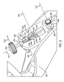
- FIG. 2 illustrates a perspective view of the blade adjuster assembly 240 in relation the angled support structure 220 in accordance with an embodiment of the invention.
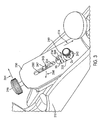
- FIG. 3 illustrates a perspective view of the plane blade 230 with the first engagement slot 234 and the second engagement slot 236 in accordance with an embodiment of the invention.
- the blade adjuster 240 may be considered to comprise structure that longitudinally moves the blade to control the distance that the blade extends through the opening 212 and that laterally moves the blade to control an angle of the edge of the blade relative to the bottom surface 214 of the plane body 210.
- the blade adjuster 240 comprises a threaded adjustment rod 241 having the adjustment knob 246 connected to upper end thereof, pivot bushing 242, lateral adjustment bushing 243, and lever cap pivot assembly 249.
- the angled support structure 220 comprises a recess or opening 222 in the upper surface 231 of the angled support structure 220.
- the recess 222 can receive several components of the blade adjuster assembly 240, for example, the threaded adjustment rod 241, the pivot bushing 242, and the lateral adjustment bushing 243.
- the recess 222 contains therein a shaped receptacle 223 for receiving therein a rearward portion 443 of the pivot bushing 242.
- the pivot bushing 242 has enlarged disk shaped upper portion 345 that has a threaded bore 346 therethrough (see FIG. 1 ), and a rearward projecting cylindrical shaped portion 443.
- the receptacle 223 has an enlarged upper disk shaped recess portion 445 to receive upper portion 345, and a cylindrical recess portion 444 to receive rearward portion 443.
- the threaded adjustment rod 241 is generally positioned underneath the plane blade 230 (as shown in FIGs. 1 and 3 ) for adjusting the distance that the edge 232 of the plane blade 230 protrudes from the opening 212 on the bottom surface 214 of the plane body 210.
- the lateral adjustment bushing 243 and the adjustment knob 246 are generally located on the opposite end of the threaded adjustment rod 241.
- the threaded adjustment rod 241 incorporates two threaded sections.
- the upper threaded section 342, closer to the adjustment knob 246 of the rod 241, is threaded with a right-handed helicity thread disposed to engage the corresponding threaded bore 346 in the pivot bushing 242.
- the lower threaded section 344 closer to the distal end of the adjustment rod 241 opposite from the adjustment knob 246, is threaded with a left hand helicity thread disposed to engage an appropriate threaded hole 348 in the lateral adjustment bushing 243.
- the longitudinal adjustment is accomplished by rotating the adjustment knob 246 on one end of the threaded adjustment rod 241 around the axis 347. Rotation of the adjustment knob 246 in a clockwise direction (as observed from the adjustment knob end of the threaded adjustment rod 241) will cause the threaded adjustment rod 241 to travel in the longitudinal direction 262 through the pivot bushing 242 toward the opening 212, and at the same time, pushing the lateral adjustment bushing 243 in the same direction.
- the pivot bushing 242 can not translate in longitudinal direction 262 with respect to the recess 222 or receptacle 223, and can receive the threaded adjustment rod 241 through a threaded channel or a threaded rod bore 346 inside the pivot bushing 242.
- the threaded adjustment rod 241 comprises only one threaded section threaded with a right-handed helicity thread disposed to engage the corresponding threaded bore 346 in the pivot bushing 242.
- the lateral adjustment bushing 243 is connected closer to the distal end of the adjustment rod 241 opposite from the adjustment knob 246, using a connector that allows for free rotation of the threaded adjustment rod 241 relative to the lateral adjustment bushing 243, but not any relative translation of the bushing 243 along the rod 241.
- the translation of the rod 241 caused by the rotation of the knob 246 will transport the bushing 243 in the desired direction along the axis 347.
- the threaded adjustment rod 241 includes only one threaded section, threaded with a left-handed helicity thread, disposed to engage an appropriate threaded hole 348 in the lateral adjustment bushing 243, while the threaded adjustment rod is arranged to include a connector that allows for free rotation of the threaded adjustment rod 241 relative to the pivot bushing 242, but not any relative translation of the pivot bushing 242 along the rod 241. In such embodiment, the rotation of the knob 246 will transport the lateral adjustment bushing 243 in the desired direction along the axis 347.
- the blade 230 also comprises the first engagement slot 234 and the second engagement slot 236 as shown in FIG. 3 .
- the lateral adjustment bushing 243 further comprises an engagement pin portion 247 positioned on top of a blade engagement cylinder portion 343.
- the cylinder portion 343 has a cylindrical surface 349 positioned within and engaging with the first engagement slot 234 in the plane blade 230 in such way that the edges 380 of the first engagement slot 234 that engages the cylindrical surface 349 can rotate around a cylindrical axis 370 experiencing negligible intensity of frictional forces.
- the engagement pin 247 is disposed to fit a corresponding opening 382 in the body of the chip breaker 282 which allows for rotation of the engagement pin 247 around the cylindrical axis 370, but not any perceptible relative translational motion generally in the longitudinal direction 262 between the engagement pin 247 and the chip breaker 282 and plane blade 230 assembly.
- the lever cap pivot assembly 249 comprises lever cap screw 244 and lever cap bushing 245.
- Screw 244 has threads 450 positioned to engage the threaded bore 378 drilled and threaded in the support structure 220 such that when the lever cap screw 244 is inserted in the threaded bore 378, the axis of symmetry of the entire lever cap pivot assembly provides a stable axis of rotation for the plane blade 230.
- the lever cap pivot assembly 249 is placed within and engages with the second engagement slot 236 on the plane blade 230. As shown in FIG. 3 , the portion of the lever cap screw 244 which protrudes through the second engagement slot 236 generally has a diameter (D1), which is narrower than a width (W1) of the second engagement slot 236 of the plane blade 230.
- the lever cap bushing 245 is positioned around the lever cap screw 244 to fill the gap caused by the difference between D1 and W1.
- the lever cap bushing 245 comprises an outer cylindrical surface 355 in contact with the edges 360 of the second engagement slot 236 in such manner that the plane blade 230 can rotate around an axis 272 through screw 244 experiencing negligible frictional force. Therefore, due to the engagement function served by the lever cap bushing 245, a second axis 272 is provided for the plane blade 230 pivot around. It is noted, however, that the diameter (D1) of the protruding portion of the lever cap screw 244 need not be narrower than the width (W1) of the second engagement slot 236.
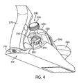
- FIG. 4 illustrates a perspective view of the plane with the lateral stabilizer 250 in accordance with an embodiment of the invention.
- the lateral stabilizer 250 inhibits a lateral movement of the plane blade 230 while still permitting a longitudinal movement of the plane blade 230.
- the lateral stabilizer 250 comprises a lock screw assembly 252 with a shaft 371 fixedly connected to a knob 372, and threaded in at one opposite end to the thread inside of cylindrical portion 443 of pivot bushing 242.
- the pivot bushing 242 is accessible through an opening in the bottom surface 226 of the angled support structure 220.
- the knob 246 and its associated rod 241 cannot be pivoted about axis 266, which prevents lateral (or arcuate) movement of lateral adjustment bushing 243 and hence prevents pivoting movement of the blade 230 and chip breaker 282 about pivot assembly 249.
- longitudinal movement of the plane blade 230 may be still permitted if the thumb set screw 286 and the lever cap screw 244 are left in positions which do not apply pressure on the chip breaker 282 - plane blade 230 assembly, sufficient to result in friction forces that prohibit the longitudinal movement of the plane blade 230.
- using the lateral stabilizer 250 can avoid or inhibit lateral movement of the plane blade 230 when the lock screw assembly 252 is tightened. In this way, longitudinal adjustment of the plane blade 230 can be made separately and independently from the lateral adjustment.
- the woodworker who intends to use the plane 200 needs only to rotate the adjustment knob 246 of the threaded adjustment rod 241 around the axis 347. This rotation will cause controlled longitudinal motion of chip breaker 282 - plane blade 230 assembly sufficient to achieve the desired longitudinal adjustments, while the tightened lateral stabilizer 250 prevents lateral blade edge movement.
- the woodworker may want to release, at least in part, the pressure on the chip breaker 282 - plane blade 230 assembly, most conveniently by appropriate relaxation of the tension applied to the thumb set screw 286, before the required or desired longitudinal adjustments of the depth of protrusion of the plane blade edge 232 through the opening 212, in order to allow for sufficiently smooth longitudinal motion of chip breaker 282 - plane blade 230 assemblies driven by the rotation of the adjustment knob 246.
- the woodworker When the woodworker desires or requires adjustments that include modifications of the angle of the edge 232 of the plane blade 230 with respect to the bottom surface of the plane body 210, the woodworker releases tension on the lateral stabilizer 250 by loosening lock screw assembly 252 to allow for rotation of the pivot bushing 242 around the axis 266. Specifically, counter-clockwise movement of the knob 372 loosens the threaded engagement between shaft 371 and pivot bushing 242 to relieve frictional engagement between pivot bushing rear surface 391 and a butting surface of the support structure 220.
- the plane blade 230 can pivot around the axis 272 of the lever cap screw 244. Consequently, a lower portion of the plane blade 230, carrying the edge 232, can simultaneously move laterally in a direction 274 and rotate with respect to the axis 272. In this way, the woodworker can adjust the angle or tilt of the edge 232 of the plane blade 230 relative to the bottom surface 214 of the plane body 210.
- the woodworker needs only to apply tension on the lock screw assembly 252 and lock the pivot bushing 242 preventing any further rotation or pivoting lateral motion. Any subsequent longitudinal adjustment can be performed, as disclosed above, without further need to repeat lateral adjustments iteratively.
- thumb set screw 286 and lateral stabilizer 250 can both be sufficiently loose to facilitate both longitudinal and lateral adjustment of the blade 230.
Landscapes
- Life Sciences & Earth Sciences (AREA)
- Engineering & Computer Science (AREA)
- Mechanical Engineering (AREA)
- Wood Science & Technology (AREA)
- Forests & Forestry (AREA)
- Harvester Elements (AREA)
- Milling, Drilling, And Turning Of Wood (AREA)
- Breakers (AREA)
- Hinges (AREA)
- Dry Shavers And Clippers (AREA)
Claims (9)
- Rabot (200) comprenant :un corps de rabot (210) ayant une ouverture positionnée dans une surface de fond du corps de rabot ;une structure de support inclinée (220) portée par le corps de rabot (210) ;une lame (230) supportée par la structure de support inclinée (220), la lame (230) ayant un bord (232) pouvant être positionné pour dépasser de l'ouverture ;un régleur de lame (240) comprenant une molette (246) reliée à une tige de réglage filetée (241), le régleur de lame (240) étant relié de façon opérationnelle à la lame (230) et qui(i) déplace longitudinalement la lame (230) de façon à commander une distance de laquelle le bord de la lame dépasse à travers l'ouverture ; et(ii) déplace latéralement la lame de façon à commander un angle du bord de la lame par rapport à la surface de fond du corps de rabot ;une douille pivot (242) agencée pour recevoir par filetage la tige de réglage (241) ; etun stabilisateur latéral (250) caractérisé en ce que le rabot (200) comprend : un ensemble formant vis de verrouillage (252) couplé à la douille pivot (242), l'ensemble formant vis de verrouillage (252) étant agencé pour tirer la douille pivot (242) contre la structure de support inclinée quand elle est serrée et pour empêcher la rotation de la douille pivot (242) et inhiber ainsi un mouvement latéral de la lame tout en permettant un mouvement longitudinal de la lame.
- Rabot selon la revendication 1, comprenant en outre un tendeur de lame (286) qui applique une force réglable à la lame (230) pour régler une quantité de force qui doit être appliquée au régleur de lame pour réaliser le mouvement longitudinal de la lame.
- Rabot selon la revendication 2, comprenant en outre un coin (284) qui applique une force à la lame à proximité d'un bord rabotant de la lame.
- Rabot selon la revendication 3, dans lequel le tendeur de lame comprend une vis de serrage (286) en prise par filetage avec le coin (284).
- Rabot selon la revendication 4, comprenant en outre un brise-copeaux (282) fixé à la lame.
- Rabot selon la revendication 5, dans lequel la vis de serrage (286) applique la force de mise en tension de lame au brise-copeaux (282).
- Rabot selon l'une quelconque des revendications 1 à 6, dans lequel le rabot (200) est un rabot d'établi comprenant un mécanisme de fixation de lame pour fixer la lame à la structure de support inclinée, et le mécanisme de fixation comprend :un brise-copeaux (282) fixé à la lame ;un coin (284) positionné sur le dessus du brise-copeaux (282) ; etune vis à serrage à main (286) en prise par filetage avec un trou fileté du coin (284) et appliquant une force au brise-copeaux.
- Rabot selon l'une quelconque des revendications 1 à 7, dans lequel la lame (230) comprend une première fente de mise en prise (234) et une seconde fente de mise en prise (236) et le régleur de lame comprend :une tige de réglage filetée (241) positionnée au-dessous de la lame pour le réglage, par l'intermédiaire d'une molette de réglage, de la distance de laquelle le bord de la lame dépasse de l'ouverture ;une douille pivot (242) pour recevoir de manière pivotante la tige de réglage filetée à travers un alésage de tige ; etune douille de réglage latéral (243) reliée de manière opérationnelle à la tige de réglage filetée (241) et disposée à l'intérieur de la première fente de mise en prise (230) dans la lame ;un ensemble formant pivot de coin disposé à l'intérieur de la seconde fente de mise en prise ; etdans lequel lorsque la tige de réglage filetée est pivotée autour de la douille pivot lors de la mise en action de la molette de réglage, la douille de réglage latéral actionne la lame par l'intermédiaire de la première fente de mise en prise, et l'ensemble formant pivot de coin fournit un contact de pivot sur lequel la lame pivote afin de régler l'angle du bord de la lame par rapport à la surface de fond du corps de rabot.
- Rabot selon la revendication 7, dans lequel l'ensemble formant pivot de coin comprend :une vis de coin dans laquelle un diamètre de la vis de coin est plus étroit qu'une largeur de la seconde fente de mise en prise de la lame ; etune douille de coin positionnée autour de la vis de coin pour fournir le contact de pivot à la seconde fente de mise en prise de la lame.
Applications Claiming Priority (1)
| Application Number | Priority Date | Filing Date | Title |
|---|---|---|---|
| US11/984,061 US7937842B2 (en) | 2007-11-13 | 2007-11-13 | Plane blade adjustment improvement |
Publications (3)
| Publication Number | Publication Date |
|---|---|
| EP2060373A2 EP2060373A2 (fr) | 2009-05-20 |
| EP2060373A3 EP2060373A3 (fr) | 2011-11-02 |
| EP2060373B1 true EP2060373B1 (fr) | 2013-04-24 |
Family
ID=40352178
Family Applications (1)
| Application Number | Title | Priority Date | Filing Date |
|---|---|---|---|
| EP08168808.7A Not-in-force EP2060373B1 (fr) | 2007-11-13 | 2008-11-11 | Raboteuse à main |
Country Status (3)
| Country | Link |
|---|---|
| US (2) | US7937842B2 (fr) |
| EP (1) | EP2060373B1 (fr) |
| CA (1) | CA2644275C (fr) |
Families Citing this family (4)
| Publication number | Priority date | Publication date | Assignee | Title |
|---|---|---|---|---|
| US7937842B2 (en) * | 2007-11-13 | 2011-05-10 | Stanley Black & Decker, Inc. | Plane blade adjustment improvement |
| US8607463B1 (en) * | 2011-02-21 | 2013-12-17 | Ricky W. Stokes | Woodworking plane using utility knife |
| US9743793B1 (en) * | 2017-03-03 | 2017-08-29 | Camelia Maria Soran | Adjustable peeling utensil |
| CN107160504A (zh) * | 2017-05-18 | 2017-09-15 | 张家港市瑞寅精密机械有限公司 | 一种木工刨及其锻造生产工艺 |
Family Cites Families (44)
| Publication number | Priority date | Publication date | Assignee | Title |
|---|---|---|---|---|
| US423424A (en) | 1890-03-11 | Bench-plane | ||
| US749827A (en) * | 1904-01-19 | Bench-plane | ||
| US556835A (en) * | 1896-03-24 | Carpenter s plane | ||
| US311136A (en) * | 1885-01-20 | Bench-plane | ||
| US306877A (en) * | 1884-10-21 | Bench-plane | ||
| US421850A (en) * | 1890-02-18 | Automatic grain-weighing machine | ||
| US1417857A (en) * | 1922-05-30 | Alsace | ||
| US516413A (en) * | 1894-03-13 | Plane | ||
| US680055A (en) * | 1900-12-04 | 1901-08-06 | Ohio Tool Company | Plane. |
| US763721A (en) | 1903-10-26 | 1904-06-28 | Union Mfg Co | Plane-iron-adjusting device. |
| US831153A (en) * | 1905-05-20 | 1906-09-18 | John A S Glans | Plane. |
| US1090225A (en) * | 1912-01-26 | 1914-03-17 | Sargent & Co | Plane. |
| GB191311526A (en) * | 1913-05-17 | 1913-07-24 | Thomas James Norris | Improvements in Planes. |
| US1459206A (en) * | 1920-06-14 | 1923-06-19 | Henry H Hardinge | Plane |
| US1439207A (en) * | 1921-12-19 | 1922-12-19 | Sanford S Vaughan | Carpenter's plane |
| GB222263A (en) * | 1923-08-02 | 1924-10-02 | Yrjo August Brander | Improvements in hand planes |
| US1553937A (en) * | 1924-03-22 | 1925-09-15 | Fine Samuel | Hand plane |
| US1696584A (en) * | 1925-10-14 | 1928-12-25 | Sandusky Tool Corp | Plane |
| FR659060A (fr) * | 1928-11-23 | 1929-06-24 | Outil à raboter à lames interchangeables et produits industriels nouveaux constitués par cet outil et les lames qu'il nécessite | |
| US1823383A (en) * | 1930-01-07 | 1931-09-15 | Sargent & Co | Plane |
| GB421850A (en) * | 1933-10-30 | 1935-01-01 | Ernest Rees Davies | Improvements in and relating to woodworking planes |
| US2423713A (en) * | 1944-11-09 | 1947-07-08 | Abraham H Lavietes | Block plane |
| CH334740A (de) * | 1955-07-25 | 1958-12-15 | Lachappelle Holzwerkzeugfabrik | Handhobel mit Stell- und Fixierorganen für das Hobeleisen |
| US2839109A (en) * | 1956-08-17 | 1958-06-17 | Jack K Wilson | Woodworking plane |
| GB861363A (en) * | 1958-12-02 | 1961-02-22 | Daventry Engineering Company L | Wood-working hand-plane |
| US3028892A (en) * | 1960-04-01 | 1962-04-10 | Sargent & Co | Carpenter's plane |
| NL283106A (fr) * | 1961-09-15 | |||
| GB1494482A (en) | 1974-10-29 | 1977-12-07 | Stanley Tools Ltd | Planes |
| SE401124B (sv) | 1975-04-30 | 1978-04-24 | Andersson Allan | Hyvel |
| SE7707875L (sv) * | 1977-07-06 | 1979-01-07 | Sandvik Ab | Hallare for hyvelsker |
| CH650192A5 (fr) | 1983-01-24 | 1985-07-15 | Samvaz Sa | Rabot. |
| EP0121738B1 (fr) | 1983-03-08 | 1987-11-25 | Frank W. Dipl.-Ing. Zarges | Rabot |
| DE3605894A1 (de) * | 1986-02-24 | 1987-08-27 | Ott Werkzeug & Maschf G | Handhobel |
| US5694696A (en) | 1996-08-12 | 1997-12-09 | Lee Valley Tools Ltd. | Scraper plane insert |
| US6615497B1 (en) | 2001-02-27 | 2003-09-09 | Lee Valley Tools, Ltd. | Bench plane |
| US7117602B2 (en) | 2003-08-11 | 2006-10-10 | Lee Valley Tools, Ltd. | Shoulder plane |
| US7444750B2 (en) | 2003-08-11 | 2008-11-04 | Lee Valley Tools, Ltd. | Scraper plane |
| US7603783B2 (en) | 2004-01-23 | 2009-10-20 | Lee Valley Tools, Ltd. | Woodworking plane with adjustable mouth |
| US20050188553A1 (en) | 2004-01-23 | 2005-09-01 | Lee Robin C. | Woodworking plane with adjustable mouth |
| JP4635802B2 (ja) | 2004-11-15 | 2011-02-23 | スズキ株式会社 | 切断工具 |
| US20060101653A1 (en) * | 2004-11-18 | 2006-05-18 | Fine Tools, Llc | Articulated iron cap for a hand plane |
| US7377044B2 (en) | 2004-11-18 | 2008-05-27 | Fine Tools, Llc | Articulated iron cap for a hand plane |
| US7530173B2 (en) | 2005-08-29 | 2009-05-12 | Economaki John J | Variable cutting angle hand plane |
| US7937842B2 (en) * | 2007-11-13 | 2011-05-10 | Stanley Black & Decker, Inc. | Plane blade adjustment improvement |
-
2007
- 2007-11-13 US US11/984,061 patent/US7937842B2/en active Active
-
2008
- 2008-11-10 CA CA2644275A patent/CA2644275C/fr not_active Expired - Fee Related
- 2008-11-11 EP EP08168808.7A patent/EP2060373B1/fr not_active Not-in-force
-
2011
- 2011-03-07 US US13/041,690 patent/US8424214B2/en not_active Expired - Fee Related
Also Published As
| Publication number | Publication date |
|---|---|
| CA2644275C (fr) | 2016-04-12 |
| US20090119936A1 (en) | 2009-05-14 |
| EP2060373A3 (fr) | 2011-11-02 |
| EP2060373A2 (fr) | 2009-05-20 |
| US20110146088A1 (en) | 2011-06-23 |
| US8424214B2 (en) | 2013-04-23 |
| CA2644275A1 (fr) | 2009-05-13 |
| US7937842B2 (en) | 2011-05-10 |
Similar Documents
| Publication | Publication Date | Title |
|---|---|---|
| US8424214B2 (en) | Plane blade adjustment improvement | |
| US5471752A (en) | High tension hacksaw frame | |
| US20090241348A1 (en) | Adjustable diameter pivot shaft for a hand tool | |
| EP0857465B1 (fr) | Dispositif de vis sécable pour plaque d'ostéosynthèse ou pour la coaptation de deux fragments d'os | |
| CN101374638A (zh) | 具有背锁机构的折叠工具 | |
| US7603783B2 (en) | Woodworking plane with adjustable mouth | |
| US6615497B1 (en) | Bench plane | |
| US5320458A (en) | Cutting tool having a cutter cartridge adjustable around two adjustment axes | |
| US7530173B2 (en) | Variable cutting angle hand plane | |
| WO2006010281A1 (fr) | Dispositif de serrage d’une plaquette d’outil dans une machine d’affûtage | |
| JP2979395B1 (ja) | 包 丁 | |
| US7712401B1 (en) | Cutting head assembly for on-vehicle brake lathe | |
| US12257735B2 (en) | Router including cutting depth locking and adjustment mechanism | |
| EP0350389B1 (fr) | Alésoir à lame rapportée | |
| JPH0244713Y2 (fr) | ||
| CN117412845A (zh) | 用于手动陶瓷切割机的切割装置 | |
| AU749019B2 (en) | Wood turning tool | |
| US7950157B2 (en) | Router plane | |
| US20060101654A1 (en) | Articulated iron cap for a hand plane | |
| US8869409B2 (en) | Hand plane with reverse angle frog | |
| JPH0231772A (ja) | スキー用安全締具 | |
| EP0609174B1 (fr) | Machine à fraiser des rainures | |
| US20060101653A1 (en) | Articulated iron cap for a hand plane | |
| JP7748707B2 (ja) | 園芸用切鋏 | |
| JP3328313B2 (ja) | 調節自在の中ぐりバー |
Legal Events
| Date | Code | Title | Description |
|---|---|---|---|
| PUAI | Public reference made under article 153(3) epc to a published international application that has entered the european phase |
Free format text: ORIGINAL CODE: 0009012 |
|
| AK | Designated contracting states |
Kind code of ref document: A2 Designated state(s): AT BE BG CH CY CZ DE DK EE ES FI FR GB GR HR HU IE IS IT LI LT LU LV MC MT NL NO PL PT RO SE SI SK TR |
|
| AX | Request for extension of the european patent |
Extension state: AL BA MK RS |
|
| PUAL | Search report despatched |
Free format text: ORIGINAL CODE: 0009013 |
|
| AK | Designated contracting states |
Kind code of ref document: A3 Designated state(s): AT BE BG CH CY CZ DE DK EE ES FI FR GB GR HR HU IE IS IT LI LT LU LV MC MT NL NO PL PT RO SE SI SK TR |
|
| AX | Request for extension of the european patent |
Extension state: AL BA MK RS |
|
| RIC1 | Information provided on ipc code assigned before grant |
Ipc: B27G 17/02 20060101AFI20110929BHEP |
|
| 17P | Request for examination filed |
Effective date: 20120501 |
|
| AKX | Designation fees paid |
Designated state(s): AT BE BG CH CY CZ DE DK EE ES FI FR GB GR HR HU IE IS IT LI LT LU LV MC MT NL NO PL PT RO SE SI SK TR |
|
| GRAP | Despatch of communication of intention to grant a patent |
Free format text: ORIGINAL CODE: EPIDOSNIGR1 |
|
| GRAS | Grant fee paid |
Free format text: ORIGINAL CODE: EPIDOSNIGR3 |
|
| GRAA | (expected) grant |
Free format text: ORIGINAL CODE: 0009210 |
|
| AK | Designated contracting states |
Kind code of ref document: B1 Designated state(s): AT BE BG CH CY CZ DE DK EE ES FI FR GB GR HR HU IE IS IT LI LT LU LV MC MT NL NO PL PT RO SE SI SK TR |
|
| RAP1 | Party data changed (applicant data changed or rights of an application transferred) |
Owner name: STANLEY BLACK & DECKER, INC. |
|
| REG | Reference to a national code |
Ref country code: GB Ref legal event code: FG4D |
|
| REG | Reference to a national code |
Ref country code: CH Ref legal event code: EP |
|
| REG | Reference to a national code |
Ref country code: AT Ref legal event code: REF Ref document number: 608315 Country of ref document: AT Kind code of ref document: T Effective date: 20130515 |
|
| REG | Reference to a national code |
Ref country code: IE Ref legal event code: FG4D |
|
| REG | Reference to a national code |
Ref country code: DE Ref legal event code: R096 Ref document number: 602008024027 Country of ref document: DE Effective date: 20130627 |
|
| REG | Reference to a national code |
Ref country code: AT Ref legal event code: MK05 Ref document number: 608315 Country of ref document: AT Kind code of ref document: T Effective date: 20130424 |
|
| REG | Reference to a national code |
Ref country code: LT Ref legal event code: MG4D |
|
| REG | Reference to a national code |
Ref country code: NL Ref legal event code: VDEP Effective date: 20130424 |
|
| PG25 | Lapsed in a contracting state [announced via postgrant information from national office to epo] |
Ref country code: AT Free format text: LAPSE BECAUSE OF FAILURE TO SUBMIT A TRANSLATION OF THE DESCRIPTION OR TO PAY THE FEE WITHIN THE PRESCRIBED TIME-LIMIT Effective date: 20130424 Ref country code: PT Free format text: LAPSE BECAUSE OF FAILURE TO SUBMIT A TRANSLATION OF THE DESCRIPTION OR TO PAY THE FEE WITHIN THE PRESCRIBED TIME-LIMIT Effective date: 20130826 Ref country code: FI Free format text: LAPSE BECAUSE OF FAILURE TO SUBMIT A TRANSLATION OF THE DESCRIPTION OR TO PAY THE FEE WITHIN THE PRESCRIBED TIME-LIMIT Effective date: 20130424 Ref country code: ES Free format text: LAPSE BECAUSE OF FAILURE TO SUBMIT A TRANSLATION OF THE DESCRIPTION OR TO PAY THE FEE WITHIN THE PRESCRIBED TIME-LIMIT Effective date: 20130804 Ref country code: SE Free format text: LAPSE BECAUSE OF FAILURE TO SUBMIT A TRANSLATION OF THE DESCRIPTION OR TO PAY THE FEE WITHIN THE PRESCRIBED TIME-LIMIT Effective date: 20130424 Ref country code: SI Free format text: LAPSE BECAUSE OF FAILURE TO SUBMIT A TRANSLATION OF THE DESCRIPTION OR TO PAY THE FEE WITHIN THE PRESCRIBED TIME-LIMIT Effective date: 20130424 Ref country code: LT Free format text: LAPSE BECAUSE OF FAILURE TO SUBMIT A TRANSLATION OF THE DESCRIPTION OR TO PAY THE FEE WITHIN THE PRESCRIBED TIME-LIMIT Effective date: 20130424 Ref country code: BE Free format text: LAPSE BECAUSE OF FAILURE TO SUBMIT A TRANSLATION OF THE DESCRIPTION OR TO PAY THE FEE WITHIN THE PRESCRIBED TIME-LIMIT Effective date: 20130424 Ref country code: GR Free format text: LAPSE BECAUSE OF FAILURE TO SUBMIT A TRANSLATION OF THE DESCRIPTION OR TO PAY THE FEE WITHIN THE PRESCRIBED TIME-LIMIT Effective date: 20130725 Ref country code: IS Free format text: LAPSE BECAUSE OF FAILURE TO SUBMIT A TRANSLATION OF THE DESCRIPTION OR TO PAY THE FEE WITHIN THE PRESCRIBED TIME-LIMIT Effective date: 20130824 Ref country code: NO Free format text: LAPSE BECAUSE OF FAILURE TO SUBMIT A TRANSLATION OF THE DESCRIPTION OR TO PAY THE FEE WITHIN THE PRESCRIBED TIME-LIMIT Effective date: 20130724 |
|
| PG25 | Lapsed in a contracting state [announced via postgrant information from national office to epo] |
Ref country code: CY Free format text: LAPSE BECAUSE OF FAILURE TO SUBMIT A TRANSLATION OF THE DESCRIPTION OR TO PAY THE FEE WITHIN THE PRESCRIBED TIME-LIMIT Effective date: 20130424 Ref country code: PL Free format text: LAPSE BECAUSE OF FAILURE TO SUBMIT A TRANSLATION OF THE DESCRIPTION OR TO PAY THE FEE WITHIN THE PRESCRIBED TIME-LIMIT Effective date: 20130424 Ref country code: HR Free format text: LAPSE BECAUSE OF FAILURE TO SUBMIT A TRANSLATION OF THE DESCRIPTION OR TO PAY THE FEE WITHIN THE PRESCRIBED TIME-LIMIT Effective date: 20130424 Ref country code: LV Free format text: LAPSE BECAUSE OF FAILURE TO SUBMIT A TRANSLATION OF THE DESCRIPTION OR TO PAY THE FEE WITHIN THE PRESCRIBED TIME-LIMIT Effective date: 20130424 Ref country code: BG Free format text: LAPSE BECAUSE OF FAILURE TO SUBMIT A TRANSLATION OF THE DESCRIPTION OR TO PAY THE FEE WITHIN THE PRESCRIBED TIME-LIMIT Effective date: 20130724 |
|
| PG25 | Lapsed in a contracting state [announced via postgrant information from national office to epo] |
Ref country code: CZ Free format text: LAPSE BECAUSE OF FAILURE TO SUBMIT A TRANSLATION OF THE DESCRIPTION OR TO PAY THE FEE WITHIN THE PRESCRIBED TIME-LIMIT Effective date: 20130424 Ref country code: DK Free format text: LAPSE BECAUSE OF FAILURE TO SUBMIT A TRANSLATION OF THE DESCRIPTION OR TO PAY THE FEE WITHIN THE PRESCRIBED TIME-LIMIT Effective date: 20130424 Ref country code: SK Free format text: LAPSE BECAUSE OF FAILURE TO SUBMIT A TRANSLATION OF THE DESCRIPTION OR TO PAY THE FEE WITHIN THE PRESCRIBED TIME-LIMIT Effective date: 20130424 Ref country code: EE Free format text: LAPSE BECAUSE OF FAILURE TO SUBMIT A TRANSLATION OF THE DESCRIPTION OR TO PAY THE FEE WITHIN THE PRESCRIBED TIME-LIMIT Effective date: 20130424 |
|
| PG25 | Lapsed in a contracting state [announced via postgrant information from national office to epo] |
Ref country code: IT Free format text: LAPSE BECAUSE OF FAILURE TO SUBMIT A TRANSLATION OF THE DESCRIPTION OR TO PAY THE FEE WITHIN THE PRESCRIBED TIME-LIMIT Effective date: 20130424 Ref country code: RO Free format text: LAPSE BECAUSE OF FAILURE TO SUBMIT A TRANSLATION OF THE DESCRIPTION OR TO PAY THE FEE WITHIN THE PRESCRIBED TIME-LIMIT Effective date: 20130424 Ref country code: NL Free format text: LAPSE BECAUSE OF FAILURE TO SUBMIT A TRANSLATION OF THE DESCRIPTION OR TO PAY THE FEE WITHIN THE PRESCRIBED TIME-LIMIT Effective date: 20130424 |
|
| PLBE | No opposition filed within time limit |
Free format text: ORIGINAL CODE: 0009261 |
|
| STAA | Information on the status of an ep patent application or granted ep patent |
Free format text: STATUS: NO OPPOSITION FILED WITHIN TIME LIMIT |
|
| 26N | No opposition filed |
Effective date: 20140127 |
|
| REG | Reference to a national code |
Ref country code: DE Ref legal event code: R097 Ref document number: 602008024027 Country of ref document: DE Effective date: 20140127 |
|
| REG | Reference to a national code |
Ref country code: CH Ref legal event code: PL |
|
| PG25 | Lapsed in a contracting state [announced via postgrant information from national office to epo] |
Ref country code: MC Free format text: LAPSE BECAUSE OF FAILURE TO SUBMIT A TRANSLATION OF THE DESCRIPTION OR TO PAY THE FEE WITHIN THE PRESCRIBED TIME-LIMIT Effective date: 20130424 Ref country code: CH Free format text: LAPSE BECAUSE OF NON-PAYMENT OF DUE FEES Effective date: 20131130 Ref country code: LI Free format text: LAPSE BECAUSE OF NON-PAYMENT OF DUE FEES Effective date: 20131130 |
|
| REG | Reference to a national code |
Ref country code: IE Ref legal event code: MM4A |
|
| PG25 | Lapsed in a contracting state [announced via postgrant information from national office to epo] |
Ref country code: IE Free format text: LAPSE BECAUSE OF NON-PAYMENT OF DUE FEES Effective date: 20131111 |
|
| PG25 | Lapsed in a contracting state [announced via postgrant information from national office to epo] |
Ref country code: TR Free format text: LAPSE BECAUSE OF FAILURE TO SUBMIT A TRANSLATION OF THE DESCRIPTION OR TO PAY THE FEE WITHIN THE PRESCRIBED TIME-LIMIT Effective date: 20130424 |
|
| PG25 | Lapsed in a contracting state [announced via postgrant information from national office to epo] |
Ref country code: HU Free format text: LAPSE BECAUSE OF FAILURE TO SUBMIT A TRANSLATION OF THE DESCRIPTION OR TO PAY THE FEE WITHIN THE PRESCRIBED TIME-LIMIT; INVALID AB INITIO Effective date: 20081111 Ref country code: LU Free format text: LAPSE BECAUSE OF NON-PAYMENT OF DUE FEES Effective date: 20131111 |
|
| PG25 | Lapsed in a contracting state [announced via postgrant information from national office to epo] |
Ref country code: MT Free format text: LAPSE BECAUSE OF FAILURE TO SUBMIT A TRANSLATION OF THE DESCRIPTION OR TO PAY THE FEE WITHIN THE PRESCRIBED TIME-LIMIT Effective date: 20130424 |
|
| REG | Reference to a national code |
Ref country code: FR Ref legal event code: PLFP Year of fee payment: 8 |
|
| REG | Reference to a national code |
Ref country code: FR Ref legal event code: PLFP Year of fee payment: 9 |
|
| REG | Reference to a national code |
Ref country code: FR Ref legal event code: PLFP Year of fee payment: 10 |
|
| REG | Reference to a national code |
Ref country code: FR Ref legal event code: PLFP Year of fee payment: 11 |
|
| PGFP | Annual fee paid to national office [announced via postgrant information from national office to epo] |
Ref country code: IT Payment date: 20181220 Year of fee payment: 7 |
|
| PG25 | Lapsed in a contracting state [announced via postgrant information from national office to epo] |
Ref country code: FR Free format text: LAPSE BECAUSE OF NON-PAYMENT OF DUE FEES Effective date: 20191130 |
|
| PGFP | Annual fee paid to national office [announced via postgrant information from national office to epo] |
Ref country code: GB Payment date: 20210922 Year of fee payment: 14 |
|
| PGFP | Annual fee paid to national office [announced via postgrant information from national office to epo] |
Ref country code: DE Payment date: 20210923 Year of fee payment: 14 |
|
| REG | Reference to a national code |
Ref country code: DE Ref legal event code: R119 Ref document number: 602008024027 Country of ref document: DE |
|
| GBPC | Gb: european patent ceased through non-payment of renewal fee |
Effective date: 20221111 |
|
| PG25 | Lapsed in a contracting state [announced via postgrant information from national office to epo] |
Ref country code: GB Free format text: LAPSE BECAUSE OF NON-PAYMENT OF DUE FEES Effective date: 20221111 Ref country code: DE Free format text: LAPSE BECAUSE OF NON-PAYMENT OF DUE FEES Effective date: 20230601 |