EP2060438A2 - Accoudoir pour un siège de véhicule automobile - Google Patents
Accoudoir pour un siège de véhicule automobile Download PDFInfo
- Publication number
- EP2060438A2 EP2060438A2 EP08169081A EP08169081A EP2060438A2 EP 2060438 A2 EP2060438 A2 EP 2060438A2 EP 08169081 A EP08169081 A EP 08169081A EP 08169081 A EP08169081 A EP 08169081A EP 2060438 A2 EP2060438 A2 EP 2060438A2
- Authority
- EP
- European Patent Office
- Prior art keywords
- backrest
- stability
- rest according
- frame element
- elements
- Prior art date
- Legal status (The legal status is an assumption and is not a legal conclusion. Google has not performed a legal analysis and makes no representation as to the accuracy of the status listed.)
- Withdrawn
Links
- 238000005452 bending Methods 0.000 claims description 12
- 238000004519 manufacturing process Methods 0.000 abstract description 16
- 238000000034 method Methods 0.000 abstract description 13
- 238000010276 construction Methods 0.000 description 13
- 229910052751 metal Inorganic materials 0.000 description 5
- 239000002184 metal Substances 0.000 description 5
- 230000008569 process Effects 0.000 description 3
- 238000003466 welding Methods 0.000 description 3
- 229910000838 Al alloy Inorganic materials 0.000 description 2
- 230000001133 acceleration Effects 0.000 description 2
- 229910052782 aluminium Inorganic materials 0.000 description 2
- XAGFODPZIPBFFR-UHFFFAOYSA-N aluminium Chemical compound [Al] XAGFODPZIPBFFR-UHFFFAOYSA-N 0.000 description 2
- 230000008859 change Effects 0.000 description 2
- 238000006243 chemical reaction Methods 0.000 description 2
- 238000005304 joining Methods 0.000 description 2
- 239000000463 material Substances 0.000 description 2
- 229920003023 plastic Polymers 0.000 description 2
- 239000004033 plastic Substances 0.000 description 2
- 229910000831 Steel Inorganic materials 0.000 description 1
- 238000010521 absorption reaction Methods 0.000 description 1
- 229910045601 alloy Inorganic materials 0.000 description 1
- 239000000956 alloy Substances 0.000 description 1
- 230000008901 benefit Effects 0.000 description 1
- 230000007423 decrease Effects 0.000 description 1
- 230000001419 dependent effect Effects 0.000 description 1
- 229910001092 metal group alloy Inorganic materials 0.000 description 1
- 238000007493 shaping process Methods 0.000 description 1
- 239000007787 solid Substances 0.000 description 1
- 239000010959 steel Substances 0.000 description 1
- 239000013585 weight reducing agent Substances 0.000 description 1
Images


Classifications
-
- B—PERFORMING OPERATIONS; TRANSPORTING
- B60—VEHICLES IN GENERAL
- B60N—SEATS SPECIALLY ADAPTED FOR VEHICLES; VEHICLE PASSENGER ACCOMMODATION NOT OTHERWISE PROVIDED FOR
- B60N2/00—Seats specially adapted for vehicles; Arrangement or mounting of seats in vehicles
- B60N2/68—Seat frames
-
- B—PERFORMING OPERATIONS; TRANSPORTING
- B60—VEHICLES IN GENERAL
- B60N—SEATS SPECIALLY ADAPTED FOR VEHICLES; VEHICLE PASSENGER ACCOMMODATION NOT OTHERWISE PROVIDED FOR
- B60N2/00—Seats specially adapted for vehicles; Arrangement or mounting of seats in vehicles
- B60N2/90—Details or parts not otherwise provided for
- B60N2/986—Side-rests
Definitions
- the invention relates to a backrest for a motor vehicle seat and in particular a backrest for a motor vehicle seat of a sports car.
- Leaning for motor vehicle seats are well known and are used in various motor vehicles, eg. B. in cars, trucks, buses, sports cars, etc., installed.
- the frame construction of this produced in large numbers backrests is usually made of deep-drawn sheet metal parts, which are welded together.
- backrests are used in vehicles that are mass-produced and therefore are not designed according to a flexible design principle in the manufacturing process with respect to the shape, which allows different designs and functions of the backrest.
- the basic principle of the invention is that a shaping frame element of the backrest is formed from a single extruded profile, which is bent into the desired shape and provided with stability elements, which have a rectangular cross section, to increase the rigidity of the backrest structure.
- An advantage of the backrest according to the invention is that different geometries, ie designs, the backrest are made possible without having to change the sequence of manufacturing steps of the backrest in any way.
- joints of the joining methods used to make this backrest structure can be easily changed in position and design via programmable controls in an automated process.
- the backrest the choice of the joints of the individual construction elements, because they can be arranged at positions that are little stressed.
- a backrest can be created with a design principle that allows to easily create different contours of the backrest, without high costs in the conversion of the manufacturing process for these different contours. A deviating strongly from the mass production design is thereby achievable.
- Fig. 1 is a perspective view of a motor vehicle seat back for a sports car according to the invention, which is constructed according to the design principle explained below, shown.
- Main element of the construction is the frame element 1, which determines the circumferential contour of the backrest.
- This frame member may be made of any metal, such. As aluminum, or of an alloy z. As an aluminum alloy, steel. Bendable plastics that have the required stiffness are also usable.
- This frame element 1 is formed from an extruded profile, preferably with a circular or tubular cross section, which is bent at certain points. It should be noted, however, that this frame member may have other cross-sectional shapes and dimensions with varying diameter.
- a single extruded profile with a uniform cross-section is advantageous in such a way that it has the same or at least similar bending radii due to production and different backrest contours on the same bending machine, for. B. a CNC-controlled bending system, can only be produced by changing the bending parameters and without additional costs.
- Fig. 1 the upper portion is formed in the head region of the backrest structure only of the frame member 1, whereby the upper portion can be made very thin, resulting in a sporty look or racing look of the backrest.
- the frame member 1 can be bent in the lower chest and / or pelvic area such that it takes over the function of the side support for the driver who controls a sports car on which may act in curves high forces.
- the lateral support can be trained and shaped accordingly.
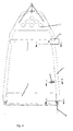
- Fig. 4 is the back off Fig. 1 shown from the front, with in Fig. 4
- Fig. 5 shows the intersection lines of the sectional views Fig. 5 . 6 and 7.
- Fig. 5 showing the sectional view along the section line AA Fig. 4
- the stability element 2 has a substantially rectangular cross-section, whose narrow longitudinal side points in the direction of travel of the vehicle.
- These stability elements 2, hereinafter referred to as side cheeks are at their lower end, as in Fig. 1 Well illustrated, connected to the frame member 1 by fasteners 8 in the form of screws or rivets.
- both ends of the frame member 1 a slotted portion into which the side cheek 2 can be used, wherein for attachment both the side cheek 2 and the frame member 1 has a bore for use of a rivet or a screw.
- the frame member 1 and the side walls 2 can also be connected to each other by means of another connection method, such as welding.
- the upper end of the side cheeks 2 is also connected to a portion of the frame member 1, wherein the connection of the upper end of the side cheeks 2 should be selected with the frame member 1 at a portion lying as far overhead as the bending strength of the backrest decreases in proportion to the backrest height.
- the higher this connection is provided the smaller the cross sections of the extruded profile of the frame member 1 can be selected, resulting in a saving in weight, cost and material.
- To connect the upper portion of the side cheeks 2 with the frame member 1 are in turn various joining methods, such as welding, Screw connections etc., conceivable.
- the portion of the frame member 1, to which the upper end of the side cheeks is attached, is preferably located just below the region of the back, which corresponds to the shoulder of a passenger.
- the portion at which the upper end of the side cheeks 2 is connected to the frame member 1 preferably in ranges between 50% and 75%, 50% and 65%, 60% and 85% or 65% and 80%.
- the side cheeks 2 have a substantially rectangular cross-section, shows the narrow side in the direction of travel of the vehicle.
- the side walls 2 connected to the frame element 1 are for the absorption of forces in the direction of travel, for.
- the cross section of the side cheeks can also be a square. It is important that the side cheeks give the frame element sufficient flexural strength against forces occurring in the longitudinal direction of the vehicle.
- the side walls 2 can z. B.
- FIG. 6 of the sectional view along the section line BB Fig. 4 An attachment of a wire mat is exemplified.
- a hook system 10 is guided by formed in the side cheeks through holes 9, in which the wire mat can be suspended by a spring 11.
- attachment options for a side airbag can be provided on the side walls 2.
- a cross member 4 is fastened at the lower end of the backrest construction as a cross connection for increasing the torsional rigidity of the backrest to the side walls 2 connected to the frame element 1.
- This cross member 4 may also be an extruded profile and is, as in Fig. 1 and 5 shown welded to the rear longitudinal portion of the side cheeks 2 at the welds 12.
- the connection of the cross member 4 with the side walls 2 need not be a welded joint, but can also be accomplished by other connection methods.
- a further cross member 7 for receiving lateral forces can be connected to the frame member 1 at an upper portion of the backrest construction.
- the sectional view along the in Fig. 4 shown section line CC is in Fig. 7 shown, in which the cross member 7 is recognizable as a multi-chamber extruded profile for reducing weight.
- This cross member 7 abuts with its ends on the outer periphery of the tubular frame member 1 and is welded thereto at a desired location.
- any other connection method can also be used.
- a release lever 13 which is also formed of an extruded profile, mounted for unlocking and tilting the back forward.
- This release lever 13 is not shown in the other figures and can be optionally mounted depending on the desired function of the backrest.
- a baffle plate 5 for supporting the head in the event of an accident or during strong acceleration can be provided which completely covers the upper portion of the frame element 1.
- this baffle plate 5 is with the outer contour of the frame member 1 having sections 5a, which are connected to the outer surface of the frame member 1, for example by welding or any other method.
- connecting elements 6 are inserted from below into the side walls 2, which have a connecting element 8 of the side wall 2 with the frame member 1 corresponding through hole, through which the connecting element 8, as in the sectional view in Fig. 5 shown, passes through and thus connects the connecting element 6 fixed to the backrest construction.
- any metal preferably aluminum or an aluminum alloy for weight reduction, other metal alloys or even bendable plastics can be used with the required stiffness.
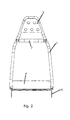
- FIG. 3 a further backrest construction according to the invention is shown, which has a different headrest portion.
- This different contour of the backrest can only be formed by changing the bending points of the frame element 1 with respect to size and location.
- the number of manufacturing steps is equal to the number of manufacturing steps of the previous backrest, although significant differences in the contour can be seen.
- Fig. 4 again shows another backrest with a different contour, which can be produced with the same number of manufacturing steps, since in turn only the bending points of the frame element 1 must be changed for the desired contour.
- the backrests illustrated and explained above have all been constructed with the same side walls 2, with the result that the progressions of the backrest contours in the lower section are similar. If strongly divergent profiles are desired in the lower section, only the side walls 2 need to be changed constructively, ie, for example, that the in Fig. 1 shown bending points 14 are changed in relation to position and size.
- a method for producing a back according to the invention with the construction principle described above.
- the course of the contour of the backrest is determined and an extruded profile, which has a uniform cross-section, bent in the desired contour of the backrest.
- this bending process is performed on a computer-controlled CNC bending machine, the variably different courses of the contour of the back, d. H. of the extruded profile possible.
- the bent extruded profile is provided with stability elements in the form of the previously explained side walls 2 and cross struts 4, 7.
- the back is equipped with connecting elements 6 such that they are connected to the side walls 2.
- the design principle of the backrest not only allows variable progressions of the backrest contour, but also meets required safety requirements, such.
Landscapes
- Engineering & Computer Science (AREA)
- Aviation & Aerospace Engineering (AREA)
- Transportation (AREA)
- Mechanical Engineering (AREA)
- Seats For Vehicles (AREA)
- Chair Legs, Seat Parts, And Backrests (AREA)
Applications Claiming Priority (1)
| Application Number | Priority Date | Filing Date | Title |
|---|---|---|---|
| DE102007054085A DE102007054085A1 (de) | 2007-11-13 | 2007-11-13 | Lehne für einen Kraftfahrzeugsitz und Verfahren zu deren Herstellung |
Publications (2)
| Publication Number | Publication Date |
|---|---|
| EP2060438A2 true EP2060438A2 (fr) | 2009-05-20 |
| EP2060438A3 EP2060438A3 (fr) | 2011-03-02 |
Family
ID=40230074
Family Applications (1)
| Application Number | Title | Priority Date | Filing Date |
|---|---|---|---|
| EP08169081A Withdrawn EP2060438A3 (fr) | 2007-11-13 | 2008-11-13 | Accoudoir pour un siège de véhicule automobile |
Country Status (2)
| Country | Link |
|---|---|
| EP (1) | EP2060438A3 (fr) |
| DE (1) | DE102007054085A1 (fr) |
Cited By (1)
| Publication number | Priority date | Publication date | Assignee | Title |
|---|---|---|---|---|
| US10661691B2 (en) | 2016-08-12 | 2020-05-26 | Lear Corporation | Integrated seat back support member for seat assemblies |
Families Citing this family (1)
| Publication number | Priority date | Publication date | Assignee | Title |
|---|---|---|---|---|
| DE102008061750A1 (de) * | 2008-12-12 | 2010-06-17 | GM Global Technology Operations, Inc., Detroit | Stützrahmen für die Rückenlehne eines Kraftfahrzeugsitzes, Kraftfahrzeugsitz mit einem solchen Stützrahmen und Verfahren zur Herstellung eines solchen Stützrahmens |
Citations (1)
| Publication number | Priority date | Publication date | Assignee | Title |
|---|---|---|---|---|
| US6926358B2 (en) | 2001-12-20 | 2005-08-09 | Delta Tooling Co., Ltd. | Impact absorbing structure and seat structure |
Family Cites Families (11)
| Publication number | Priority date | Publication date | Assignee | Title |
|---|---|---|---|---|
| US3131971A (en) * | 1962-06-29 | 1964-05-05 | Air Lab Service Co Inc | Frame for pilot's seat |
| DE4303006C2 (de) * | 1993-02-03 | 1998-07-02 | Keiper Recaro Gmbh Co | Rückenlehne für Fahrzeugsitze, insbesondere Kraftfahrzeugsitze |
| DE19514941C2 (de) * | 1995-04-22 | 1998-06-10 | Keiper Recaro Gmbh Co | Rückenlehne für Fahrzeugsitze, insbesondere Kraftfahrzeugsitze |
| US5746476A (en) * | 1995-06-02 | 1998-05-05 | Aluminum Company Of America | Load bearing automotive bench seat assembly |
| JP2000506095A (ja) * | 1996-02-29 | 2000-05-23 | ブロムデル,ペーテル | 衝突車両中において乗員を安全に拘束する方法と該方法を実施すべく構成されたシート |
| DE19613164C2 (de) * | 1996-04-02 | 1998-06-10 | Keiper Recaro Gmbh Co | Rückenlehne für Fahrzeugsitze |
| US5947542A (en) * | 1997-10-09 | 1999-09-07 | Lear Corporation | Vehicle seat assembly with collapsible riser |
| DE29816819U1 (de) * | 1998-09-22 | 1998-12-03 | VAW Aluminium AG, 53117 Bonn | Fahrzeugsitz |
| DE10126014C1 (de) * | 2001-05-28 | 2003-01-09 | Porsche Ag | Klappbare Rückenlehne für einen Rücksitz eines Kraftfahrzeugs |
| DE10249394B4 (de) * | 2002-10-23 | 2004-09-09 | Euromotive Ges.M.B.H. & Co. Kg | Sitz- oder Lehnenrahmenteil eines Sitzes mit Neigungsversteller |
| DE102004026023A1 (de) * | 2004-05-27 | 2005-12-22 | Recaro Aircraft Seating Gmbh & Co. Kg | Sitz, insbesondere Fluggastsitz |
-
2007
- 2007-11-13 DE DE102007054085A patent/DE102007054085A1/de not_active Ceased
-
2008
- 2008-11-13 EP EP08169081A patent/EP2060438A3/fr not_active Withdrawn
Patent Citations (1)
| Publication number | Priority date | Publication date | Assignee | Title |
|---|---|---|---|---|
| US6926358B2 (en) | 2001-12-20 | 2005-08-09 | Delta Tooling Co., Ltd. | Impact absorbing structure and seat structure |
Cited By (1)
| Publication number | Priority date | Publication date | Assignee | Title |
|---|---|---|---|---|
| US10661691B2 (en) | 2016-08-12 | 2020-05-26 | Lear Corporation | Integrated seat back support member for seat assemblies |
Also Published As
| Publication number | Publication date |
|---|---|
| EP2060438A3 (fr) | 2011-03-02 |
| DE102007054085A1 (de) | 2009-05-14 |
Similar Documents
| Publication | Publication Date | Title |
|---|---|---|
| DE4138647C2 (de) | Rücklehnenrahmen für einen Sitz | |
| EP0765252B1 (fr) | Banquette pour vehicules a moteur, notamment autocaravanes | |
| DE69517285T2 (de) | Sitzarmatur für Kraftfahrzeuge | |
| DE19802873B4 (de) | Rückenlehnenrahmen | |
| DE69604619T2 (de) | Fahrzeugsitzstruktur mit integriertem Sicherheitsgurt | |
| DE19826732B4 (de) | Rücklehnenkonstruktion | |
| DE102010018638B4 (de) | Fahrzeug mit einer Trägerstruktur eines Sitzquerträgers | |
| DE69320459T2 (de) | Hochfester kraftfahrzeugsitzrahmen und verfahren | |
| DE60120041T2 (de) | Vorderwagenaufbau für Kraftfahrzeuge | |
| DE10304642A1 (de) | Fahrzeugsitzanordnung | |
| DE202019105594U1 (de) | Schwingträger für ein Fahrzeug | |
| EP2994367B1 (fr) | Montant pour une structure de carrosserie de véhicule automobile, procédé de fabrication d'un montant et structure de carrosserie de véhicule automobile | |
| EP2427345B1 (fr) | Châssis de dossier de siège de véhicule | |
| DE19905215A1 (de) | Sitz | |
| DE19519779A1 (de) | Rahmenseitenteil einer Karosserie von Kraftfahrzeugen, insbesondere Personenkraftwagen, und Verfahren zu dessen Herstellung | |
| DE102010048350A1 (de) | Bodengruppe für eine Mehrzahl von Bauvarianten einer Karosserie eines Personenkraftwagens | |
| DE102009017374A1 (de) | Verfahren zur Herstellung einer Strukturkomponente für ein Kraftfahrzeug | |
| DE202010018333U1 (de) | Armaturenbrettstruktur für Kraftfahrzeuge und Kraftfahrzeuge mit einer solchen Struktur | |
| DE102013218096B4 (de) | Rückenlehne für einen Sitz, insbesondere einen Fahrzeugsitz | |
| DE102013015357A1 (de) | Fahrzeugsitz mit modularem Fahrzeugsitzrahmen | |
| DE102011012124A1 (de) | Bodengruppe für eine Mehrzahl von Bauvarianten einer Karosserie eines Personenkraftwagens, insbesondere mit Heckantriebsaggregat | |
| EP0790902B1 (fr) | Procede de production du bati du dossier d'un siege de vehicule | |
| EP2060438A2 (fr) | Accoudoir pour un siège de véhicule automobile | |
| DE4315521C1 (de) | Verfahren zum Fertigen eines Rahmens | |
| DE10240042A1 (de) | Sitzbank für ein Fahrzeug mit einer kippbaren Rücklehne |
Legal Events
| Date | Code | Title | Description |
|---|---|---|---|
| PUAI | Public reference made under article 153(3) epc to a published international application that has entered the european phase |
Free format text: ORIGINAL CODE: 0009012 |
|
| AK | Designated contracting states |
Kind code of ref document: A2 Designated state(s): AT BE BG CH CY CZ DE DK EE ES FI FR GB GR HR HU IE IS IT LI LT LU LV MC MT NL NO PL PT RO SE SI SK TR |
|
| AX | Request for extension of the european patent |
Extension state: AL BA MK RS |
|
| RAP1 | Party data changed (applicant data changed or rights of an application transferred) |
Owner name: ALUTECH GESELLSCHAFT M.B.H. |
|
| PUAL | Search report despatched |
Free format text: ORIGINAL CODE: 0009013 |
|
| AK | Designated contracting states |
Kind code of ref document: A3 Designated state(s): AT BE BG CH CY CZ DE DK EE ES FI FR GB GR HR HU IE IS IT LI LT LU LV MC MT NL NO PL PT RO SE SI SK TR |
|
| AX | Request for extension of the european patent |
Extension state: AL BA MK RS |
|
| 17P | Request for examination filed |
Effective date: 20110902 |
|
| AKX | Designation fees paid |
Designated state(s): DE FR GB IT |
|
| 17Q | First examination report despatched |
Effective date: 20150923 |
|
| STAA | Information on the status of an ep patent application or granted ep patent |
Free format text: STATUS: THE APPLICATION IS DEEMED TO BE WITHDRAWN |
|
| 18D | Application deemed to be withdrawn |
Effective date: 20160405 |