EP2060466B1 - Système d'assistance à la conduite embarqué dans un véhicule automobile - Google Patents
Système d'assistance à la conduite embarqué dans un véhicule automobile Download PDFInfo
- Publication number
- EP2060466B1 EP2060466B1 EP08105343A EP08105343A EP2060466B1 EP 2060466 B1 EP2060466 B1 EP 2060466B1 EP 08105343 A EP08105343 A EP 08105343A EP 08105343 A EP08105343 A EP 08105343A EP 2060466 B1 EP2060466 B1 EP 2060466B1
- Authority
- EP
- European Patent Office
- Prior art keywords
- vehicle
- speed
- driver assistance
- assistance system
- driver
- Prior art date
- Legal status (The legal status is an assumption and is not a legal conclusion. Google has not performed a legal analysis and makes no representation as to the accuracy of the status listed.)
- Not-in-force
Links
Images


Classifications
-
- B—PERFORMING OPERATIONS; TRANSPORTING
- B60—VEHICLES IN GENERAL
- B60W—CONJOINT CONTROL OF VEHICLE SUB-UNITS OF DIFFERENT TYPE OR DIFFERENT FUNCTION; CONTROL SYSTEMS SPECIALLY ADAPTED FOR HYBRID VEHICLES; ROAD VEHICLE DRIVE CONTROL SYSTEMS FOR PURPOSES NOT RELATED TO THE CONTROL OF A PARTICULAR SUB-UNIT
- B60W30/00—Purposes of road vehicle drive control systems not related to the control of a particular sub-unit, e.g. of systems using conjoint control of vehicle sub-units
- B60W30/18—Propelling the vehicle
- B60W30/18009—Propelling the vehicle related to particular drive situations
-
- B—PERFORMING OPERATIONS; TRANSPORTING
- B60—VEHICLES IN GENERAL
- B60T—VEHICLE BRAKE CONTROL SYSTEMS OR PARTS THEREOF; BRAKE CONTROL SYSTEMS OR PARTS THEREOF, IN GENERAL; ARRANGEMENT OF BRAKING ELEMENTS ON VEHICLES IN GENERAL; PORTABLE DEVICES FOR PREVENTING UNWANTED MOVEMENT OF VEHICLES; VEHICLE MODIFICATIONS TO FACILITATE COOLING OF BRAKES
- B60T7/00—Brake-action initiating means
- B60T7/12—Brake-action initiating means for automatic initiation; for initiation not subject to will of driver or passenger
- B60T7/22—Brake-action initiating means for automatic initiation; for initiation not subject to will of driver or passenger initiated by contact of vehicle, e.g. bumper, with an external object, e.g. another vehicle, or by means of contactless obstacle detectors mounted on the vehicle
-
- B—PERFORMING OPERATIONS; TRANSPORTING
- B60—VEHICLES IN GENERAL
- B60W—CONJOINT CONTROL OF VEHICLE SUB-UNITS OF DIFFERENT TYPE OR DIFFERENT FUNCTION; CONTROL SYSTEMS SPECIALLY ADAPTED FOR HYBRID VEHICLES; ROAD VEHICLE DRIVE CONTROL SYSTEMS FOR PURPOSES NOT RELATED TO THE CONTROL OF A PARTICULAR SUB-UNIT
- B60W30/00—Purposes of road vehicle drive control systems not related to the control of a particular sub-unit, e.g. of systems using conjoint control of vehicle sub-units
- B60W30/14—Adaptive cruise control
- B60W30/16—Control of distance between vehicles, e.g. keeping a distance to preceding vehicle
-
- G—PHYSICS
- G01—MEASURING; TESTING
- G01S—RADIO DIRECTION-FINDING; RADIO NAVIGATION; DETERMINING DISTANCE OR VELOCITY BY USE OF RADIO WAVES; LOCATING OR PRESENCE-DETECTING BY USE OF THE REFLECTION OR RERADIATION OF RADIO WAVES; ANALOGOUS ARRANGEMENTS USING OTHER WAVES
- G01S13/00—Systems using the reflection or reradiation of radio waves, e.g. radar systems; Analogous systems using reflection or reradiation of waves whose nature or wavelength is irrelevant or unspecified
- G01S13/88—Radar or analogous systems specially adapted for specific applications
- G01S13/93—Radar or analogous systems specially adapted for specific applications for anti-collision purposes
- G01S13/931—Radar or analogous systems specially adapted for specific applications for anti-collision purposes of land vehicles
-
- B—PERFORMING OPERATIONS; TRANSPORTING
- B60—VEHICLES IN GENERAL
- B60W—CONJOINT CONTROL OF VEHICLE SUB-UNITS OF DIFFERENT TYPE OR DIFFERENT FUNCTION; CONTROL SYSTEMS SPECIALLY ADAPTED FOR HYBRID VEHICLES; ROAD VEHICLE DRIVE CONTROL SYSTEMS FOR PURPOSES NOT RELATED TO THE CONTROL OF A PARTICULAR SUB-UNIT
- B60W2530/00—Input parameters relating to vehicle conditions or values, not covered by groups B60W2510/00 or B60W2520/00
- B60W2530/10—Weight
-
- B—PERFORMING OPERATIONS; TRANSPORTING
- B60—VEHICLES IN GENERAL
- B60W—CONJOINT CONTROL OF VEHICLE SUB-UNITS OF DIFFERENT TYPE OR DIFFERENT FUNCTION; CONTROL SYSTEMS SPECIALLY ADAPTED FOR HYBRID VEHICLES; ROAD VEHICLE DRIVE CONTROL SYSTEMS FOR PURPOSES NOT RELATED TO THE CONTROL OF A PARTICULAR SUB-UNIT
- B60W2540/00—Input parameters relating to occupants
- B60W2540/18—Steering angle
-
- B—PERFORMING OPERATIONS; TRANSPORTING
- B60—VEHICLES IN GENERAL
- B60W—CONJOINT CONTROL OF VEHICLE SUB-UNITS OF DIFFERENT TYPE OR DIFFERENT FUNCTION; CONTROL SYSTEMS SPECIALLY ADAPTED FOR HYBRID VEHICLES; ROAD VEHICLE DRIVE CONTROL SYSTEMS FOR PURPOSES NOT RELATED TO THE CONTROL OF A PARTICULAR SUB-UNIT
- B60W2552/00—Input parameters relating to infrastructure
- B60W2552/15—Road slope, i.e. the inclination of a road segment in the longitudinal direction
-
- B—PERFORMING OPERATIONS; TRANSPORTING
- B60—VEHICLES IN GENERAL
- B60W—CONJOINT CONTROL OF VEHICLE SUB-UNITS OF DIFFERENT TYPE OR DIFFERENT FUNCTION; CONTROL SYSTEMS SPECIALLY ADAPTED FOR HYBRID VEHICLES; ROAD VEHICLE DRIVE CONTROL SYSTEMS FOR PURPOSES NOT RELATED TO THE CONTROL OF A PARTICULAR SUB-UNIT
- B60W2554/00—Input parameters relating to objects
- B60W2554/40—Dynamic objects, e.g. animals, windblown objects
- B60W2554/404—Characteristics
- B60W2554/4042—Longitudinal speed
-
- B—PERFORMING OPERATIONS; TRANSPORTING
- B60—VEHICLES IN GENERAL
- B60W—CONJOINT CONTROL OF VEHICLE SUB-UNITS OF DIFFERENT TYPE OR DIFFERENT FUNCTION; CONTROL SYSTEMS SPECIALLY ADAPTED FOR HYBRID VEHICLES; ROAD VEHICLE DRIVE CONTROL SYSTEMS FOR PURPOSES NOT RELATED TO THE CONTROL OF A PARTICULAR SUB-UNIT
- B60W2554/00—Input parameters relating to objects
- B60W2554/80—Spatial relation or speed relative to objects
- B60W2554/804—Relative longitudinal speed
-
- B—PERFORMING OPERATIONS; TRANSPORTING
- B60—VEHICLES IN GENERAL
- B60W—CONJOINT CONTROL OF VEHICLE SUB-UNITS OF DIFFERENT TYPE OR DIFFERENT FUNCTION; CONTROL SYSTEMS SPECIALLY ADAPTED FOR HYBRID VEHICLES; ROAD VEHICLE DRIVE CONTROL SYSTEMS FOR PURPOSES NOT RELATED TO THE CONTROL OF A PARTICULAR SUB-UNIT
- B60W50/00—Details of control systems for road vehicle drive control not related to the control of a particular sub-unit, e.g. process diagnostic or vehicle driver interfaces
- B60W50/08—Interaction between the driver and the control system
- B60W50/14—Means for informing the driver, warning the driver or prompting a driver intervention
-
- G—PHYSICS
- G01—MEASURING; TESTING
- G01S—RADIO DIRECTION-FINDING; RADIO NAVIGATION; DETERMINING DISTANCE OR VELOCITY BY USE OF RADIO WAVES; LOCATING OR PRESENCE-DETECTING BY USE OF THE REFLECTION OR RERADIATION OF RADIO WAVES; ANALOGOUS ARRANGEMENTS USING OTHER WAVES
- G01S13/00—Systems using the reflection or reradiation of radio waves, e.g. radar systems; Analogous systems using reflection or reradiation of waves whose nature or wavelength is irrelevant or unspecified
- G01S13/88—Radar or analogous systems specially adapted for specific applications
- G01S13/93—Radar or analogous systems specially adapted for specific applications for anti-collision purposes
- G01S13/931—Radar or analogous systems specially adapted for specific applications for anti-collision purposes of land vehicles
- G01S2013/932—Radar or analogous systems specially adapted for specific applications for anti-collision purposes of land vehicles using own vehicle data, e.g. ground speed, steering wheel direction
-
- G—PHYSICS
- G01—MEASURING; TESTING
- G01S—RADIO DIRECTION-FINDING; RADIO NAVIGATION; DETERMINING DISTANCE OR VELOCITY BY USE OF RADIO WAVES; LOCATING OR PRESENCE-DETECTING BY USE OF THE REFLECTION OR RERADIATION OF RADIO WAVES; ANALOGOUS ARRANGEMENTS USING OTHER WAVES
- G01S13/00—Systems using the reflection or reradiation of radio waves, e.g. radar systems; Analogous systems using reflection or reradiation of waves whose nature or wavelength is irrelevant or unspecified
- G01S13/88—Radar or analogous systems specially adapted for specific applications
- G01S13/93—Radar or analogous systems specially adapted for specific applications for anti-collision purposes
- G01S13/931—Radar or analogous systems specially adapted for specific applications for anti-collision purposes of land vehicles
- G01S2013/9321—Velocity regulation, e.g. cruise control
-
- G—PHYSICS
- G01—MEASURING; TESTING
- G01S—RADIO DIRECTION-FINDING; RADIO NAVIGATION; DETERMINING DISTANCE OR VELOCITY BY USE OF RADIO WAVES; LOCATING OR PRESENCE-DETECTING BY USE OF THE REFLECTION OR RERADIATION OF RADIO WAVES; ANALOGOUS ARRANGEMENTS USING OTHER WAVES
- G01S13/00—Systems using the reflection or reradiation of radio waves, e.g. radar systems; Analogous systems using reflection or reradiation of waves whose nature or wavelength is irrelevant or unspecified
- G01S13/88—Radar or analogous systems specially adapted for specific applications
- G01S13/93—Radar or analogous systems specially adapted for specific applications for anti-collision purposes
- G01S13/931—Radar or analogous systems specially adapted for specific applications for anti-collision purposes of land vehicles
- G01S2013/9325—Radar or analogous systems specially adapted for specific applications for anti-collision purposes of land vehicles for inter-vehicle distance regulation, e.g. navigating in platoons
-
- G—PHYSICS
- G01—MEASURING; TESTING
- G01S—RADIO DIRECTION-FINDING; RADIO NAVIGATION; DETERMINING DISTANCE OR VELOCITY BY USE OF RADIO WAVES; LOCATING OR PRESENCE-DETECTING BY USE OF THE REFLECTION OR RERADIATION OF RADIO WAVES; ANALOGOUS ARRANGEMENTS USING OTHER WAVES
- G01S13/00—Systems using the reflection or reradiation of radio waves, e.g. radar systems; Analogous systems using reflection or reradiation of waves whose nature or wavelength is irrelevant or unspecified
- G01S13/88—Radar or analogous systems specially adapted for specific applications
- G01S13/93—Radar or analogous systems specially adapted for specific applications for anti-collision purposes
- G01S13/931—Radar or analogous systems specially adapted for specific applications for anti-collision purposes of land vehicles
- G01S2013/9327—Sensor installation details
- G01S2013/93271—Sensor installation details in the front of the vehicles
Definitions
- the invention relates to a driver assistance system for motor vehicles, in particular for trucks or vans.
- ACC systems which allow to measure the distance to a preceding vehicle by means of a radar or Lidarsensors and to regulate the speed of the own vehicle so that the preceding vehicle is tracked at a reasonable safety distance.
- lane departure warning systems and lane departure warning systems are known in which about a video camera the apron of the vehicle is monitored, lane markings on the road are identified by electronic image analysis and the driver receives an audible or haptic warning or automatic intervention takes place in the steering, if the driver is about to leave the lane he is driving.
- overtaking assistants are known in which with suitable locating devices the rear space of the vehicle and / or the blind spot next to the vehicle is monitored and the driver is sent a warning signal when he is about to is to make an overtaking maneuver but the secondary lane is not clear ( DE 102 45 334 A1 ).
- a driver assistance system according to the preamble of claim 1 is known.
- This system comprises a sensory system for recognizing a following driving situation, an electronic judging device for evaluating a differential speed which is likely to occur in an overtaking maneuver, and an output device for outputting a signal indicative of an overtaking maneuver, depending on the evaluation result.
- the object of the invention is to provide a driver assistance system that contributes to an improvement in the flow of traffic and thus to a reduction in the risk of congestion and accidents.
- the sensory system has an inertial longitudinal acceleration sensor for measuring the longitudinal acceleration of the vehicle and the evaluation device is adapted to determine the road gradient by comparing the measured with the inertial longitudinal acceleration sensor acceleration with the change of directly measured speed and an estimate of the differential speed taking into account the maximum To determine the engine power of the vehicle and the road gradient.
- the driver assistance system helps the driver to assess the situation more accurately and to refrain from overtaking maneuvers that would lead to a significant obstruction of the other road users. Since in some countries, for example in Germany overtaking with too low a differential speed represents a fine, such a driver assistance system also uses the vehicle owner and the respective driver.
- the power reserve of the drive system of the own vehicle is taken into account in the estimation of the differential speed. If the vehicle has a cruise control function or an ACC system, and the measurement of the relative speed of the preceding vehicle shows that the absolute speed of the preceding vehicle is only a little, for example less than 10 km / h, above the desired speed set for the own vehicle, then the driver should be prevented from overtaking. When the vehicle is fully loaded, it will often occur on uphill sections that the actual speed of the own vehicle remains behind the set desired speed.
- the road gradient can be determined by comparing the measured acceleration with the change of the directly measured speed. This in turn makes it possible to deduce the payload of the vehicle, taking into account the current operating state of the engine and the actual speed. For a given slope can be based on this data predict the speed that could reach the own vehicle in an overtaking process (with unchanged slope) maximum. In conjunction with the directly measured relative speed of the vehicle ahead, this allows an accurate estimation of the differential speed.
- the signal generated by the output device can be transmitted, for example as a warning signal to the driver. It can However, optionally or additionally also be used to limit the maximum speed of the vehicle for a certain time so that eliminates the driver of the occasion for a lane change.
- a detection device which recognizes a driver's intention to overtake on the basis of the driver's steering behavior and / or on the status of the direction indicator (indicator) so that the warning signal and / or the maximum speed limit are only output if the driver actually attaching to an overtaking maneuver.
- the vehicle is also equipped with a lane departure warning system and / or a lane departure warning system, then its sensor, z.
- a lane departure warning system and / or a lane departure warning system As an electronic camera, also for detecting a lane change and thus used to detect the driver's intention to overtake.
- the sensory system for detecting a subsequent driving situation can also include sensors, in particular locating devices such as radar sensors and the like, which are shared by a plurality of driver assistance systems, for example an ACC system and the system according to the invention. Since, for example, the relative speed of the vehicle in front can be measured directly with the aid of a radar sensor, it is particularly easy to estimate the differential speed that is likely to occur during an overtaking maneuver. If, for example, the own vehicle already travels at almost the maximum speed that is possible under the given conditions (gradient, charge), and the radar sensor measures only a very low relative speed when approaching a preceding vehicle, for example 5 km / h or less, it can be foreseen that the differential speed during the overtaking process will hardly exceed the measured relative speed.
- sensors in particular locating devices such as radar sensors and the like, which are shared by a plurality of driver assistance systems, for example an ACC system and the system according to the invention. Since, for example, the relative speed of the vehicle in front can be measured directly with the aid of a
- the signal of the longitudinal acceleration sensor in conjunction with tracking the actual speed of the own vehicle, may also be used in addition to or instead of the locating device to detect a following driving situation. For example, if the speed of your own vehicle over a longer period, about several minutes constantly in a speed range that is just below the Maximum speed of the vehicle, or the maximum possible speed on the basis of the engine power and the load, this suggests that there is another vehicle in front of the driver's own vehicle which determines the speed of the vehicle, ie that there is a following driving situation. In this case, slight fluctuations in the speed of the driver's own vehicle can be evaluated as an additional indicator, since such fluctuations rarely occur in a free-riding situation, but are typically caused by the driver correcting the distance to the vehicle in front.
- the system can also use this gradient information to calculate in advance the maximum speed of the own vehicle for the route section which requires an overtaking procedure would, and if it turns out that the speed of the vehicle in front decreases with increasing slope less (because it is not so heavily loaded), even if the current differential speed is still relatively high, it can be discouraged from overtaking.
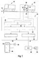
- Fig. 1 schematically two trucks 10, 12 are shown, which drive on a rising road 14.
- the rear truck 12 is equipped with a driver assistance system 16 according to the invention, which is shown here as a block.
- this driver assistance system is formed by an electronic data processing system which communicates with various sensory components on the input side and outputs output signals to a human / machine interface or various actuators of the vehicle or possibly also to another driver assistance system.
- the sensory components with which the driver assistance system 16 communicates include a radar sensor 18, a video camera 20, which is installed in the front of the vehicle 12 State sensor 22 for detecting the state of a flasher switch of the vehicle, a power sensor 24, here symbolized by an accelerator pedal sensor, for detecting the current engine power of the truck 12, and a longitudinal acceleration sensor 26, for example, be integrated into an unspecified ESP system of the truck 12 can.
- the radar sensor 18 is used to locate vehicles ahead of the truck 12 and to measure their distances and relative speeds and their azimuth. Based on the azimuth angle can then decide whether a located vehicle, such as in the example shown, the truck 10, is located on the track of the own vehicle (truck 12). This situation, in which a vehicle driving ahead in its own lane is tracked, will be referred to below as a follow-up driving situation.
- the longitudinal acceleration sensor 26 measures the vehicle acceleration component acting in the direction of the longitudinal axis of the truck 12. Since this sensor is an inertial sensor, the gravitational force acting on it is also interpreted as acceleration. Thus, with the help of the longitudinal acceleration sensor 26, the slope of the roadway 14 can be measured. For example, if the actual speed of the truck 12 measured by a conventional tachometer is constant, then the acceleration measured by the longitudinal acceleration sensor 26 equals the acceleration g multiplied by the tangent of the pitch angle ⁇ of the roadway 14. By comparing this gradient with one from the power sensor 24 or z. B. a motor management system supplied measure of the engine power can then determine the load condition of the truck 12. From this loading condition can in conjunction with the known maximum engine power and the measured slope of the road 14, the theoretical maximum speed of the truck 12 are calculated.
- the video camera 20 is arranged to take a picture of the lane immediately in front of the truck 12, including lane markings on the lane.
- the lane markings are detected so that it can be seen whether the own vehicle, so the truck 12, is approximately at the lane center, or is about to run over one of the lane boundaries.
- a lane departure warning system may use this information to alert the driver by an audible signal, by vibration of the steering wheel or the like, that he is about to leave his current lane.
- the state sensor 22 detects the state of the turn signal of the truck 12. If, for example, the left turn signal is set and then the video system recognizes that the truck 12 overruns the left lane boundary, no lane departure warning is issued because it is assumed that the lane Driver deliberately makes a lane change, about to overtake the leading truck 10.
- the evaluation of the data of the video camera 20 and the state sensor 22 takes place in the driver assistance system 16 in a recognition module 28, which serves to detect any overtaking intention of the driver.
- the driver assistance system 16 includes a recognition module 30 for recognizing a subsequent driving situation.
- this recognition can be achieved simply by evaluating the signal of the radar sensor 18.
- the following driving situation can also be detected on the basis of the actual speed of the own vehicle and on the basis of the data of the longitudinal acceleration sensor 26, as will be explained in more detail below.
- the signals of the power sensor 24 and the longitudinal acceleration sensor 26, together with the data from the radar sensor 18, serve to estimate the differential speed V diff in an evaluation module 32 by which the truck 12 is expected to be faster than the truck 10, if the the former overtakes the latter.
- the evaluation module 32 activates a first output device 34 for outputting a warning signal W to the driver.
- this warning signal consists in an acoustic signal output via a loudspeaker 36 and additionally in the lighting or flashing of a light display 38, which, as in some known overtaking assistants, is integrated in the left-hand outside mirror 40 of the truck 12.
- the evaluation module 32 also activates a second output device 42 which effects the output of a disable signal S which results in the maximum speed of the truck 12 for some Time is reduced so that the preceding truck 10 can not be overhauled.
- this inhibit signal is output to another driver assistance system, namely an ACC system 44, which also uses the signals of the radar sensor 18 and automatically controls the speed of the truck 12 to track the truck 10 at a reasonable safety distance.
- This is symbolized here by the action of the ACC system 44 on a throttle valve 46.
- the driver can override the ACC system 44 with the gas pedal if he wants to trigger an overtaking operation.
- the blocking signal S generated by the output device 42 has the effect of preventing this oversteering for a certain time.
- Another effect of the blocking signal S may be that the regulation of the distance to the truck 10 is continued even if the driver of the truck 12 ignored the warning signal W and has initiated a lane change, so that the truck 10 is no longer in the own lane is immediately preceding vehicle. In this way, the driver is forced to cancel the already initiated overtaking.
- the light indicator 38 can also be activated as soon as a follow-up driving situation is detected and the evaluation shows that the differential speed for a passing process is too low, even if no overtaking intent of the driver is recognizable.
- the driver will look into the exterior mirror 40 before he sets the left turn signal and attaches to an overtaking maneuver.
- the "preventive" output of the warning signal W via the light indicator 38 can be prevented so that the driver by setting the turn signal announces an overtaking, which then finally not executed.
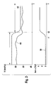
- Fig. 2 is indicated by the curve 48, a typical speed profile illustrating the operation of the driver assistance system 16.
- the curve 50 indicates the slope of the road at each location of the truck 12 to.
- the truck 12 drives on a level road (slope zero) at a speed that is just below the permissible in Germany for trucks on motorways maximum speed of 80 km / h. lies.
- the desired speed is set at 80 km / h, but can not be met, since the radar sensor 18 detects the slightly slower preceding truck 10 and causes a speed adjustment.
- the recognition module 30 thus recognizes a subsequent driving situation.
- the following driving situation could also be detected in a modified form without the radar sensor 18 alone based on the course of the speed. Namely, if there were no preceding vehicle, the driver of the truck 12 would probably keep his foot on the accelerator pedal or, if present, activate the cruise control to constantly maintain the top speed of 80 km / h. Since the road does not increase, the slightly lower speed can not be caused by the lack of engine power, but the only plausible reason is the presence of the preceding truck 10.
- the apparent in the curve 48 slight fluctuations in speed indicate that the From time to time the driver corrects the distance to the preceding truck 10 with the gas pedal or by switching the tempomat on and off.
- the dashed line curve 52 in Fig. 2 indicates the power reserve of the truck 12, that is, the maximum speed of this truck achievable under the given conditions. It is assumed here that the speed is throttled to 90 km / h, so that the maximum speed is limited to 90 km / h on a flat road or on slopes. In contrast, on uphill gradients, the maximum speed is determined by the pitch and loading condition of the truck 12 and can be determined by comparing the actual engine power with the road grade measured by the longitudinal acceleration sensor 26.
- the evaluation module 32 determines that the initiation of an overtaking operation can no longer be approved, and if necessary, the light indicator 38 is activated.
- the warning signal W and the blocking signal S are output as soon as the recognition module 28 recognizes an overtaking intention of the driver on the basis of the set direction indicator and on the basis of the approach recognized by the video camera 20 to the left lane boundary.
- Fig. 3 illustrates the same situation as Fig. 2 "but with the difference that now the truck 12 is empty, so that its maximum speed (curve 52) is less dependent on the road gradient.With unchanged load condition of the preceding truck 10, this means that after the time t1, the differential speed does not decrease but even greater, so there are plenty of power reserves available for a quick overtaking process.
- Fig. 4 illustrates a situation in which the truck 12 travels a smoothly ascending route until time t4, but due to the load, the truck 12 is already traveling close to the power limit (curve 52).
- a follow-up driving situation is detected by the radar sensor or by evaluation of the speed curve, and since the differential speed is well below 10 km / h, the evaluation module 32 determines already at this time that the conditions for a speedy passing process are not met.
- the roadway inclination increases, resulting in a transient increase in the differential speed, since the truck 12 reaches the steeper section later than the preceding truck 10.
- the evaluation module 32 operates with some hysteresis, so that it does not "discarding" an overtaking procedure when the differential speed temporarily reaches the threshold of 10 km / h. If, at time t5, the truck 12 has also reached the steeper section, the power limit drops again almost to the actual speed, confirming that there are no reserves for overtaking.
Landscapes
- Engineering & Computer Science (AREA)
- Mechanical Engineering (AREA)
- Transportation (AREA)
- Radar, Positioning & Navigation (AREA)
- Automation & Control Theory (AREA)
- Remote Sensing (AREA)
- Physics & Mathematics (AREA)
- Electromagnetism (AREA)
- Computer Networks & Wireless Communication (AREA)
- General Physics & Mathematics (AREA)
- Control Of Driving Devices And Active Controlling Of Vehicle (AREA)
- Traffic Control Systems (AREA)
- Controls For Constant Speed Travelling (AREA)
Claims (9)
- Système d'assistance au conducteur pour véhicules automobiles (12), comprenant un système de détection (18, 26, 30) pour reconnaître une situation de circulation à venir, un dispositif d'estimation électronique (32) pour estimer une vitesse différentielle (Vdiff) qui se produira vraisemblablement lors d'une manoeuvre de dépassement et un dispositif de diffusion (34, 42) pour délivrer un signal (W, S) qui indique, en fonction du résultat de l'estimation, si une manoeuvre de dépassement est réalisable, caractérisé en ce que le système de détection présente un détecteur d'accélération longitudinale à inertie (26) pour mesurer l'accélération longitudinale du véhicule (12) et le dispositif d'estimation (32) est configuré pour déterminer la pente de la voie de circulation en comparant l'accélération mesurée avec le détecteur d'accélération longitudinale à inertie (26) avec la modification de la vitesse mesurée directement et pour déterminer une valeur estimée pour la vitesse différentielle en tenant compte de la puissance maximale du moteur du véhicule (12) et de la pente de la voie de circulation.
- Système d'assistance au conducteur selon la revendication 1, caractérisé en ce que le système de détection présente un appareil de localisation (18) qui est en mesure de localiser le véhicule qui précède (10) et de mesurer sa distance.
- Système d'assistance au conducteur selon la revendication 2, caractérisé en ce que le dispositif d'estimation (32) est configuré pour déterminer la vitesse différentielle (Vdiff) en tenant compte de la vitesse relative du véhicule qui précède (10) mesurée par l'appareil de localisation (18).
- Système d'assistance au conducteur selon l'une des revendications précédentes, caractérisé en ce que le système de détection est configuré pour reconnaître une situation de conduite à venir au moyen de la courbe dans le temps de la vitesse et de l'accélération longitudinale du véhicule (12).
- Système d'assistance au conducteur selon l'une des revendications précédentes, caractérisé en ce qu'au moins un signal délivré par le dispositif de diffusion (34, 42) est un signal d'alerte (W) qui indique au conducteur qu'un dépassement n'est pas réalisable.
- Système d'assistance au conducteur selon l'une des revendications précédentes, caractérisé en ce qu'au moins un signal délivré par le dispositif de diffusion (34, 42) est un signal de blocage (S) qui provoque une restriction temporaire de la vitesse maximale du véhicule (12).
- Système d'assistance au conducteur selon l'une des revendications précédentes, caractérisé en ce qu'il est prévu un module de reconnaissance (28) pour reconnaître une intention de dépassement du conducteur et en ce que le dispositif de diffusion (34, 42) est configuré pour délivrer le signal (W, S) lorsqu'une intention de dépassement du conducteur est reconnue.
- Système d'assistance au conducteur selon la revendication 7, caractérisé en ce que le module de reconnaissance (28) est relié avec un détecteur d'état (24) qui détecte l'état d'un indicateur de sens de déplacement du véhicule.
- Système d'assistance au conducteur selon la revendication 7 ou 8, caractérisé en ce que le module de reconnaissance (28) reçoit des signaux de la part d'un système vidéo (20) qui est configuré pour reconnaître le marquage horizontal sur la voie de circulation.
Applications Claiming Priority (1)
| Application Number | Priority Date | Filing Date | Title |
|---|---|---|---|
| DE102007054095A DE102007054095A1 (de) | 2007-11-13 | 2007-11-13 | Fahrerassistenzsystem für Kraftfahrzeuge |
Publications (2)
| Publication Number | Publication Date |
|---|---|
| EP2060466A1 EP2060466A1 (fr) | 2009-05-20 |
| EP2060466B1 true EP2060466B1 (fr) | 2012-02-15 |
Family
ID=40280802
Family Applications (1)
| Application Number | Title | Priority Date | Filing Date |
|---|---|---|---|
| EP08105343A Not-in-force EP2060466B1 (fr) | 2007-11-13 | 2008-09-15 | Système d'assistance à la conduite embarqué dans un véhicule automobile |
Country Status (2)
| Country | Link |
|---|---|
| EP (1) | EP2060466B1 (fr) |
| DE (1) | DE102007054095A1 (fr) |
Cited By (1)
| Publication number | Priority date | Publication date | Assignee | Title |
|---|---|---|---|---|
| CN105182342A (zh) * | 2015-09-29 | 2015-12-23 | 长安大学 | 一种颠簸路面车辆雷达目标位置的追踪装置及追踪方法 |
Families Citing this family (8)
| Publication number | Priority date | Publication date | Assignee | Title |
|---|---|---|---|---|
| DE102010042115A1 (de) * | 2010-10-07 | 2012-04-12 | Robert Bosch Gmbh | Verfahren und Informationssystem zur Information eines Fahrzeugführers über Bedingungen eines geplanten Überholvorganges |
| CN106546257B (zh) * | 2013-04-16 | 2019-09-13 | 合肥杰发科技有限公司 | 车距测量方法及装置、车辆相对速度测量方法及装置 |
| CN106428006B (zh) * | 2016-12-20 | 2019-05-31 | 北京小米移动软件有限公司 | 车辆控制方法及装置 |
| FR3062833B1 (fr) * | 2017-02-10 | 2019-04-05 | Peugeot Citroen Automobiles Sa | Procede de conduite autonome d’un vehicule automobile |
| DE102017002221A1 (de) * | 2017-03-08 | 2018-09-13 | Man Truck & Bus Ag | Technik zur Überwachung eines Totwinkelbereichs |
| DE102017213211A1 (de) | 2017-08-01 | 2019-02-07 | Robert Bosch Gmbh | Verfahren zum Abbrechen eines bereits eingeleiteten Spurwechsels |
| DE102017213629A1 (de) * | 2017-08-07 | 2019-02-07 | Robert Bosch Gmbh | Fahrerassistenzsystem zur Unterstützung eines Überholvorgangs bei Kraftfahrzeugen |
| DE102018211590A1 (de) * | 2018-07-12 | 2020-01-16 | Audi Ag | Verfahren zum Betrieb eines Fahrerassistenzsystems eines Kraftfahrzeugs und Kraftfahrzeug |
Family Cites Families (8)
| Publication number | Priority date | Publication date | Assignee | Title |
|---|---|---|---|---|
| GB871641A (en) * | 1958-10-29 | 1961-06-28 | Gen Motors Corp | Improved motor road vehicle control system |
| DE3622447C1 (en) | 1986-07-04 | 1988-01-28 | Daimler Benz Ag | Device for displaying overtaking recommendations for the driver of a vehicle |
| DE4313568C1 (de) * | 1993-04-26 | 1994-06-16 | Daimler Benz Ag | Verfahren zur Leithilfe für einen Fahrspurwechsel durch ein Kraftfahrzeug |
| DE19725656B4 (de) | 1996-06-27 | 2014-11-20 | Volkswagen Ag | Sicherheits-Überholsystem |
| DE19937489B4 (de) * | 1999-08-07 | 2009-07-09 | Volkswagen Ag | Verfahren zur Überwachung eines Fahrspurwechsels eines Kraftfahrzeuges |
| DE10114187A1 (de) * | 2001-03-23 | 2002-09-26 | Bosch Gmbh Robert | Verfahren und Vorrichtung zur Unterstützung eines Überholvorgangs bei Kraftfahrzeugen |
| DE10160900B4 (de) | 2001-12-12 | 2017-03-23 | Man Truck & Bus Ag | Fahrgeschwindigkeitsregler für ein Kraftfahrzeug, insbesondere Nutzfahrzeug |
| DE10245334A1 (de) | 2002-09-27 | 2004-04-08 | Robert Bosch Gmbh | Navigationsvorrichtung |
-
2007
- 2007-11-13 DE DE102007054095A patent/DE102007054095A1/de not_active Withdrawn
-
2008
- 2008-09-15 EP EP08105343A patent/EP2060466B1/fr not_active Not-in-force
Cited By (2)
| Publication number | Priority date | Publication date | Assignee | Title |
|---|---|---|---|---|
| CN105182342A (zh) * | 2015-09-29 | 2015-12-23 | 长安大学 | 一种颠簸路面车辆雷达目标位置的追踪装置及追踪方法 |
| CN105182342B (zh) * | 2015-09-29 | 2018-11-09 | 长安大学 | 一种颠簸路面车辆雷达目标位置的追踪装置及追踪方法 |
Also Published As
| Publication number | Publication date |
|---|---|
| DE102007054095A1 (de) | 2009-05-14 |
| EP2060466A1 (fr) | 2009-05-20 |
Similar Documents
| Publication | Publication Date | Title |
|---|---|---|
| EP2060466B1 (fr) | Système d'assistance à la conduite embarqué dans un véhicule automobile | |
| EP2130194B1 (fr) | Dispositif d'alerte de collision pour véhicules automobiles | |
| EP1381530B1 (fr) | Procede et dispositif assistant une manoeuvre de depassement pour des vehicules automobiles | |
| DE10015300B4 (de) | Verfahren und Vorrichtung zur Steuerung der Fahrgeschwindigkeit eines Fahrzeugs | |
| EP1940665B1 (fr) | Regulateur de distance et de vitesse a detection d'embouteillage | |
| EP1292462B1 (fr) | Procede et systeme pour reguler la distance entre un vehicule de reference et un vehicule roulant devant ce dernier | |
| EP2252491B1 (fr) | Assistant de guidage longitudinal comportant une fonction d'assistance latérale pour des véhicules motorisés | |
| EP3191355B1 (fr) | Système de régulation de distance destiné à des véhicules automobiles | |
| DE102009008403A1 (de) | Verfahren zur Steuerung und Regelung des Verkehrsflusses | |
| DE102005023185A1 (de) | Spurwechselassistent für Kraftfahrzeuge | |
| DE102005045018A1 (de) | Vorrichtung zur Längsführung eines Kraftfahrzeugs | |
| DE102011109697A1 (de) | Verfahren zum Betreiben eines Kraftfahrzeuges und Fahrerassistenzsystem zur Durchführung des Verfahrens | |
| DE102007038059A1 (de) | Verfahren zum Betreiben eines Abstandsregelsystems für Fahrzeuge und Fahrzeug mit einem Abstandsregelsystem zur Durchführung des Verfahrens | |
| DE102014210174B4 (de) | Bestimmen eines kritischen Fahrzeugzustands und einer Fahrzeugmindestentfernung | |
| EP1736797A1 (fr) | Système d'assistance du conducteur avec interface de système de navigation | |
| DE10321412B4 (de) | Vorrichtung zur Längsführung eines Kraftfahrzeugs | |
| WO2019243007A1 (fr) | Système d'aide à la conduite et procédé de conduite automatisée à guidage longitudinal automatisé | |
| DE102013006172A1 (de) | Verfahren zum Betreiben eines Fahrerassistenzsystems und Fahrerassistenzsystem | |
| EP1900586B1 (fr) | Dispositif de régulation de distance doté d'un affichage de l'objet cible | |
| DE102011077975A1 (de) | Fahrerassistenzsystem für ein Kraftfahrzeug bestehend aus einem abstandsbezogenen Fahrgeschwindigkeitsregelsystem und aus einem Engstellenassistenzsystem | |
| DE102004028591A1 (de) | Verfahren zum Bereitstellen von fahrstreckenabhängigen Informationen | |
| DE102013003219A1 (de) | Unterstützung eines Fahrers eines Kraftfahrzeugs beim Fahren auf einer Überholspur einer zumindest zweispurigen Straße | |
| DE102004047081A1 (de) | Fahrerassistenzsystem mit Bildverarbeitungseinrichtung | |
| WO2006087282A1 (fr) | Procede pour detecter un processus de depassement imminent | |
| WO2024120585A1 (fr) | Procédé de sélection d'objet pour un système d'assistance, et système d'assistance |
Legal Events
| Date | Code | Title | Description |
|---|---|---|---|
| PUAI | Public reference made under article 153(3) epc to a published international application that has entered the european phase |
Free format text: ORIGINAL CODE: 0009012 |
|
| AK | Designated contracting states |
Kind code of ref document: A1 Designated state(s): AT BE BG CH CY CZ DE DK EE ES FI FR GB GR HR HU IE IS IT LI LT LU LV MC MT NL NO PL PT RO SE SI SK TR |
|
| AX | Request for extension of the european patent |
Extension state: AL BA MK RS |
|
| 17P | Request for examination filed |
Effective date: 20091120 |
|
| AKX | Designation fees paid |
Designated state(s): DE FR GB IT |
|
| 17Q | First examination report despatched |
Effective date: 20100113 |
|
| GRAP | Despatch of communication of intention to grant a patent |
Free format text: ORIGINAL CODE: EPIDOSNIGR1 |
|
| GRAS | Grant fee paid |
Free format text: ORIGINAL CODE: EPIDOSNIGR3 |
|
| GRAA | (expected) grant |
Free format text: ORIGINAL CODE: 0009210 |
|
| AK | Designated contracting states |
Kind code of ref document: B1 Designated state(s): DE FR GB IT |
|
| REG | Reference to a national code |
Ref country code: GB Ref legal event code: FG4D Free format text: NOT ENGLISH |
|
| REG | Reference to a national code |
Ref country code: DE Ref legal event code: R096 Ref document number: 502008006402 Country of ref document: DE Effective date: 20120412 |
|
| PG25 | Lapsed in a contracting state [announced via postgrant information from national office to epo] |
Ref country code: IT Free format text: LAPSE BECAUSE OF FAILURE TO SUBMIT A TRANSLATION OF THE DESCRIPTION OR TO PAY THE FEE WITHIN THE PRESCRIBED TIME-LIMIT Effective date: 20120215 |
|
| PLBE | No opposition filed within time limit |
Free format text: ORIGINAL CODE: 0009261 |
|
| STAA | Information on the status of an ep patent application or granted ep patent |
Free format text: STATUS: NO OPPOSITION FILED WITHIN TIME LIMIT |
|
| 26N | No opposition filed |
Effective date: 20121116 |
|
| REG | Reference to a national code |
Ref country code: DE Ref legal event code: R097 Ref document number: 502008006402 Country of ref document: DE Effective date: 20121116 |
|
| REG | Reference to a national code |
Ref country code: FR Ref legal event code: PLFP Year of fee payment: 9 |
|
| REG | Reference to a national code |
Ref country code: FR Ref legal event code: PLFP Year of fee payment: 10 |
|
| REG | Reference to a national code |
Ref country code: FR Ref legal event code: PLFP Year of fee payment: 11 |
|
| PGFP | Annual fee paid to national office [announced via postgrant information from national office to epo] |
Ref country code: FR Payment date: 20190923 Year of fee payment: 12 |
|
| PGFP | Annual fee paid to national office [announced via postgrant information from national office to epo] |
Ref country code: GB Payment date: 20190924 Year of fee payment: 12 |
|
| PGFP | Annual fee paid to national office [announced via postgrant information from national office to epo] |
Ref country code: DE Payment date: 20191125 Year of fee payment: 12 |
|
| REG | Reference to a national code |
Ref country code: DE Ref legal event code: R119 Ref document number: 502008006402 Country of ref document: DE |
|
| GBPC | Gb: european patent ceased through non-payment of renewal fee |
Effective date: 20200915 |
|
| PG25 | Lapsed in a contracting state [announced via postgrant information from national office to epo] |
Ref country code: FR Free format text: LAPSE BECAUSE OF NON-PAYMENT OF DUE FEES Effective date: 20200930 Ref country code: DE Free format text: LAPSE BECAUSE OF NON-PAYMENT OF DUE FEES Effective date: 20210401 |
|
| PG25 | Lapsed in a contracting state [announced via postgrant information from national office to epo] |
Ref country code: GB Free format text: LAPSE BECAUSE OF NON-PAYMENT OF DUE FEES Effective date: 20200915 |