EP2060497A2 - Tonneau - Google Patents
Tonneau Download PDFInfo
- Publication number
- EP2060497A2 EP2060497A2 EP08168454A EP08168454A EP2060497A2 EP 2060497 A2 EP2060497 A2 EP 2060497A2 EP 08168454 A EP08168454 A EP 08168454A EP 08168454 A EP08168454 A EP 08168454A EP 2060497 A2 EP2060497 A2 EP 2060497A2
- Authority
- EP
- European Patent Office
- Prior art keywords
- insert ring
- region
- barrel
- closure
- hull
- Prior art date
- Legal status (The legal status is an assumption and is not a legal conclusion. Google has not performed a legal analysis and makes no representation as to the accuracy of the status listed.)
- Granted
Links
Images







Classifications
-
- B—PERFORMING OPERATIONS; TRANSPORTING
- B65—CONVEYING; PACKING; STORING; HANDLING THIN OR FILAMENTARY MATERIAL
- B65D—CONTAINERS FOR STORAGE OR TRANSPORT OF ARTICLES OR MATERIALS, e.g. BAGS, BARRELS, BOTTLES, BOXES, CANS, CARTONS, CRATES, DRUMS, JARS, TANKS, HOPPERS, FORWARDING CONTAINERS; ACCESSORIES, CLOSURES, OR FITTINGS THEREFOR; PACKAGING ELEMENTS; PACKAGES
- B65D7/00—Containers having bodies formed by interconnecting or uniting two or more rigid, or substantially rigid, components made wholly or mainly of metal
- B65D7/02—Containers having bodies formed by interconnecting or uniting two or more rigid, or substantially rigid, components made wholly or mainly of metal characterised by shape
- B65D7/04—Containers having bodies formed by interconnecting or uniting two or more rigid, or substantially rigid, components made wholly or mainly of metal characterised by shape of curved cross-section, e.g. cans of circular or elliptical cross-section
- B65D7/045—Casks, barrels, or drums in their entirety, e.g. beer barrels, i.e. presenting most of the following features like rolling beads, double walls, reinforcing and supporting beads for end walls
-
- B—PERFORMING OPERATIONS; TRANSPORTING
- B65—CONVEYING; PACKING; STORING; HANDLING THIN OR FILAMENTARY MATERIAL
- B65D—CONTAINERS FOR STORAGE OR TRANSPORT OF ARTICLES OR MATERIALS, e.g. BAGS, BARRELS, BOTTLES, BOXES, CANS, CARTONS, CRATES, DRUMS, JARS, TANKS, HOPPERS, FORWARDING CONTAINERS; ACCESSORIES, CLOSURES, OR FITTINGS THEREFOR; PACKAGING ELEMENTS; PACKAGES
- B65D1/00—Rigid or semi-rigid containers having bodies formed in one piece, e.g. by casting metallic material, by moulding plastics, by blowing vitreous material, by throwing ceramic material, by moulding pulped fibrous material or by deep-drawing operations performed on sheet material
- B65D1/12—Cans, casks, barrels, or drums
- B65D1/14—Cans, casks, barrels, or drums characterised by shape
-
- B—PERFORMING OPERATIONS; TRANSPORTING
- B65—CONVEYING; PACKING; STORING; HANDLING THIN OR FILAMENTARY MATERIAL
- B65D—CONTAINERS FOR STORAGE OR TRANSPORT OF ARTICLES OR MATERIALS, e.g. BAGS, BARRELS, BOTTLES, BOXES, CANS, CARTONS, CRATES, DRUMS, JARS, TANKS, HOPPERS, FORWARDING CONTAINERS; ACCESSORIES, CLOSURES, OR FITTINGS THEREFOR; PACKAGING ELEMENTS; PACKAGES
- B65D11/00—Containers having bodies formed by interconnecting or uniting two or more rigid, or substantially rigid, components made wholly or mainly of plastics material
- B65D11/02—Containers having bodies formed by interconnecting or uniting two or more rigid, or substantially rigid, components made wholly or mainly of plastics material of curved cross-section
- B65D11/06—Drums or barrels
-
- B—PERFORMING OPERATIONS; TRANSPORTING
- B65—CONVEYING; PACKING; STORING; HANDLING THIN OR FILAMENTARY MATERIAL
- B65D—CONTAINERS FOR STORAGE OR TRANSPORT OF ARTICLES OR MATERIALS, e.g. BAGS, BARRELS, BOTTLES, BOXES, CANS, CARTONS, CRATES, DRUMS, JARS, TANKS, HOPPERS, FORWARDING CONTAINERS; ACCESSORIES, CLOSURES, OR FITTINGS THEREFOR; PACKAGING ELEMENTS; PACKAGES
- B65D11/00—Containers having bodies formed by interconnecting or uniting two or more rigid, or substantially rigid, components made wholly or mainly of plastics material
- B65D11/02—Containers having bodies formed by interconnecting or uniting two or more rigid, or substantially rigid, components made wholly or mainly of plastics material of curved cross-section
- B65D11/06—Drums or barrels
- B65D11/08—Arrangements of filling or discharging apertures
-
- B—PERFORMING OPERATIONS; TRANSPORTING
- B65—CONVEYING; PACKING; STORING; HANDLING THIN OR FILAMENTARY MATERIAL
- B65D—CONTAINERS FOR STORAGE OR TRANSPORT OF ARTICLES OR MATERIALS, e.g. BAGS, BARRELS, BOTTLES, BOXES, CANS, CARTONS, CRATES, DRUMS, JARS, TANKS, HOPPERS, FORWARDING CONTAINERS; ACCESSORIES, CLOSURES, OR FITTINGS THEREFOR; PACKAGING ELEMENTS; PACKAGES
- B65D7/00—Containers having bodies formed by interconnecting or uniting two or more rigid, or substantially rigid, components made wholly or mainly of metal
- B65D7/12—Containers having bodies formed by interconnecting or uniting two or more rigid, or substantially rigid, components made wholly or mainly of metal characterised by wall construction or by connections between walls
-
- B—PERFORMING OPERATIONS; TRANSPORTING
- B65—CONVEYING; PACKING; STORING; HANDLING THIN OR FILAMENTARY MATERIAL
- B65D—CONTAINERS FOR STORAGE OR TRANSPORT OF ARTICLES OR MATERIALS, e.g. BAGS, BARRELS, BOTTLES, BOXES, CANS, CARTONS, CRATES, DRUMS, JARS, TANKS, HOPPERS, FORWARDING CONTAINERS; ACCESSORIES, CLOSURES, OR FITTINGS THEREFOR; PACKAGING ELEMENTS; PACKAGES
- B65D7/00—Containers having bodies formed by interconnecting or uniting two or more rigid, or substantially rigid, components made wholly or mainly of metal
- B65D7/12—Containers having bodies formed by interconnecting or uniting two or more rigid, or substantially rigid, components made wholly or mainly of metal characterised by wall construction or by connections between walls
- B65D7/40—Containers having bodies formed by interconnecting or uniting two or more rigid, or substantially rigid, components made wholly or mainly of metal characterised by wall construction or by connections between walls with walls formed with filling or emptying apertures
-
- B—PERFORMING OPERATIONS; TRANSPORTING
- B65—CONVEYING; PACKING; STORING; HANDLING THIN OR FILAMENTARY MATERIAL
- B65D—CONTAINERS FOR STORAGE OR TRANSPORT OF ARTICLES OR MATERIALS, e.g. BAGS, BARRELS, BOTTLES, BOXES, CANS, CARTONS, CRATES, DRUMS, JARS, TANKS, HOPPERS, FORWARDING CONTAINERS; ACCESSORIES, CLOSURES, OR FITTINGS THEREFOR; PACKAGING ELEMENTS; PACKAGES
- B65D2401/00—Tamper-indicating means
- B65D2401/50—Tamper-band co-operating with intermediate ring connected to the container
Definitions
- Barrel in particular beverage keg, comprising a hull and the end of the hull on the one hand a lid and on the other hand a floor.
- Such barrels can be made of either plastic or sheet metal and are preferably used for storage of liquids, such as beverages.
- the advantage of the solution according to the invention is to be seen in that on the one hand the hull of the barrel has an aesthetically pleasing shape, especially according to the shape of a well-known beverage keg, but on the other hand also due to the flattening can be placed without rolling on a support surface and thus is stable.
- the round shape has a substantially circular cross-sectional shape except for the region of the flattening, so that, except for the flattening itself, the fuselage corresponds to the classic shape of a barrel.
- the flattening can extend over the entire longitudinal axis of the barrel.
- An aesthetically pleasing form provides that the hull is bulbous in the direction of a longitudinal axis.
- the flattening extends in the direction of a longitudinal axis of the barrel over a bulbous region of the fuselage.
- the flattening can be arranged when the flattening extends as far as conical regions of the fuselage extending to the respective cover or floor.
- lid and / or the floor a similar appearance to a wooden barrel, it is provided as an alternative or in addition to the features described above, that the lid and / or the bottom of a lid mirror or floor mirror and a cover mirror or floor mirror from the fuselage away bulging ring area have.
- a particularly advantageous solution provides that the annular region engages over a retaining element of the fuselage and thus by the formation of the annular region on the lid or bottom is possible to give the barrel according to the invention a visually pleasing appearance, in particular an appearance similar to that of a barrique barrel ,
- the retaining element in various ways with the ring area is effective.
- annular region cooperates with an outer wall with the retaining element.
- annular region cooperates with an inner wall with the retaining element.
- the annular region with an outer wall extends in the direction of the fuselage and is held on the hull via this outer wall.
- the annular region has a curl, which can be latched into a fuselage bead.
- the hull bead is formed by a retracted end portion of the hull.
- the hull bead can be realized when the hull bead is limited to the lid and bottom through an end-rolled area.
- annular region can be fixed to the fuselage with an inner wall.
- the annular region can be fixed to the inner wall on a clamping collar of the fuselage.
- Such a clamping collar of the fuselage is formed, for example, by a retracted region of the respective end region of the fuselage.
- such a clamping collar has an approximately cylindrical to a longitudinal axis of the fuselage extending clamping wall.
- an opening for a dispensing device is provided alternatively or in addition to the features described above in the barrel.
- the barrel according to the invention serves to form a housing for a liquid bag with a dispensing device, wherein the dispensing device of the liquid bag can be guided out of the barrel through the opening in the lid.
- the closure unit could be designed so that it is disassembled as a whole in turn to pass the dispensing device through the opening.
- closure unit has a permanently fixed at the edge of the opening insert ring.
- the insert ring is so securely fixed to the opening that it remains fixed in the opening under normal action on the closure unit, preferably only by destroying the shape of the insert ring or the lid of the opening can be removed.
- a permanent fixation of the insert ring takes place at the edge of the opening to the effect that the opening of the lid, in particular the edge thereof, at least partially digs into the material of the insert ring.
- a closure element is held on the insert ring.
- the closure element could for example be releasably fixed to the insert ring.
- closure element is connected in a manufacturing state via a tear-off with the insert ring.
- closure element and insert ring as a single part and to mount as such in the opening of the lid. This is a significant advantage in terms of cost-effective production and installation of a closure unit.
- the closure element is connected to the insert ring in an original state via a tear-off region.
- the closure element can be fixed on the insert ring after release of the tear-off region.
- the detachment of the tear-off region could take place completely independently of the fixing of the closure element to the insert ring.
- a particularly favorable solution provides that the closure element can be inserted by a movement for releasing the tear-off in the insert ring.
- Such a solution makes it possible, for example, to automatically perform the release of the closure element from the insert ring by releasing the tear-off region and inserting the closure element into the insert ring.
- a fixation of the closure element can be done in a variety of ways by a fixing.
- the closure element is provided with a fixing element which can be fixed on the insert ring in order to be able to fix or fix the closure element on the insert ring in a simple manner.
- the fixing element in such a way that it is arranged on a side of the closure element facing the tear-off region.
- closure element on a side opposite the tear-off region has the fixing element, which can be fixed to the insert ring.
- the fixing element can be formed in various ways.
- An advantageous solution provides that the fixing element is a fixing ring, which can be inserted into a passage opening of the insert ring and fixed in this.
- fixation of the fixing on the insert ring can be done in a variety of ways.
- a particularly advantageous solution provides that the fixing element can be fixed by a latching connection on the insert ring.
- closure unit has a holding part for fixing the dispensing device an insert ring.
- This holding part could, for example, also be connected to the insert ring separately via a tear-off element.
- closure element carries the holding part.
- closure element comprises a holding part, that is, that the holding part is part of the closure element and thus integrated in this.
- the holding part of the closure element can be inserted as such after loosening a closure body part, that is to say that the holding part and the closure body part form at least a part of the closure element, if not the entire closure element.
- the closure body part is connected by a tear-off with the holding part, so that the closure body part can be solved in a simple manner by the holding part to use the holding part as such.
- An expedient embodiment provides here that a release of the closure body part releases a free space of the holding part for receiving the dispensing device.
- closure body part closes in the state connected to the holding part, the free space of the holding part and thus holding part and closure body part either partially or as a whole can form the closure element.
- the free space is designed as an approximately U-like or keyhole-like cutout in the holding part, in which then the dispensing device, for example with a collar, can be used.
- the holding part engages in a receptacle on a collar of the dispensing device.
- the holding part is supported on the insert part, so that it is prevented by the holding part that the dispensing device can be moved through the insert part back into the interior of the barrel.
- Such support of the dispensing device on the insert part can be done by a mere application of the holding part on the insert.
- the holding part is fixable on the insert part, for example, characterized in that the holding part and the insert part can be connected to one another by a latching connection.
- the holding part has two holding elements which receive the dispensing device between them.
- An exemplary solution provides that the holding part has two fork-shaped holding fingers, which can be brought into engagement with the receptacle in the collar of the dispensing device.
- the invention relates to a closure unit for an opening of a barrel, which is formed according to one or more of the preceding features.
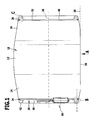
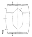
- the trunk 10 has, as in Fig. 1 and 2 illustrated, both in the bulbous region 12 and in the conical regions 14 and 16 to a flat 34 a substantially circular cross-section, wherein the flattening 34 serves to be able to stably place the beverage keg on a support surface 36, wherein a longitudinal axis 38 of the beverage keg approximately parallel to the support surface 36 extends.
- the flattening 34 extends essentially around the bulbous region 12, but also beyond it into the conical regions 14 and 16, preferably over approximately half of the extent of the conical regions 14 and 16 in the direction of the end regions 24 and 26.
- the cover 30 comprises a cover mirror 40, to which radially outwardly adjoins a side facing the trunk 10 side of the lid mirror 40 via this uplifting annular region 42, which following the lid mirror 40 has a conical inner wall 44 and a the inner wall 44 has adjoining end wall 46, which then in turn merges into a conically widening towards the fuselage 10 outer wall 48.
- the outer wall 48 extends beyond the lid mirror in the direction of the fuselage 10 and has a radially inner curl 50, which engages in a bead 52 of the end region 24.
- the bead 52 of the end region 24 is formed, for example, by a radially inwardly drawn end wall 54 of the end region 24, in front of which there is a rolled-over region 56 at a distance, so that the curl 50 rests on the end wall 54 on the one hand and on the rolled-up region on the other hand the bead 52 formed by both is fixed to the end region 24 of the hull 10.
- the outer wall 48 which widens conically starting from the end wall 46 of the cover 30 in the direction of the fuselage 10, has such a radial elasticity in the region of the curl 50 that the curl 50 projects on a side of the rolled-over region 56 facing away from the end wall 54 put on and deform by pressure on the lid 30 so radially that the Anrollung 50 over the rolled-over region 56 away in the bead 52 is movable and locked there.
- the floor is also provided with a floor mirror 60, which is surrounded radially in the same way as in the cover 30 by a ring area 62 which rises above the floor mirror 60 opposite the fuselage 10 and following the floor level 60 has an inner wall 64 which merges into an end wall 66 and this end wall 66 in turn merges into an outer wall 68, which extends in a conically widening over the floor mirror 60 out in the direction of the end portion 26 and also in turn carries a Anrollung 70 which in a Beading 72 of the end portion 26 engages, which in turn lies between an end wall 74 of the end portion 26 and a rolled-over portion 76 of the end portion 26.
- the bottom 32 is latched to the hull 10 by the curl 70 engaging the bead 72 of the end portion 26, in which case, for example, the rolled portion 76 has a larger cross section, so that a greater elastic deformation of the outer wall 68 is required to move the Anrollung70 over the rolled portion 76 away in the bead 72 to fix the bottom 32, so that the fixation of the bottom 32 on the hull 10 is solvable with greater force than the fixation of the lid 30 on the hull 10th
- the ring 42 or 62 overlaps the respective bead 52 or 72 and thus makes the respective end region 24 or 26 of the hull 10 invisible.
- the cover 30 in the cover mirror 40 is provided with an opening 80 which lies on a side facing the flattening 34 near the annular region 42.
- the opening 80 serves to pass through this a dispensing device 82 which is arranged in an interior 84 of the drinks barrel, and serves to remove a beverage from a beverage bag or beverage bag 86, wherein the beverage bag 86 is formed as a foil bag in the filled Condition the inner space 84 of the beverage keg substantially fills and upon removal of beverage from the beverage bag 86 through the dispensing device 82 as it is removed in the drink collapses and thus increasingly fill the interior 84, so that the possibility exists, the drink to remove it from the beverage bag 86 without venting and thereby increase the shelf life of the beverage in the beverage bag 86 after a partial emptying.
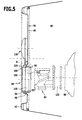
- the insert ring 92 comprises a support flange 98 which can be placed on an outer side of the lid 40, and an integrally formed on the support flange 98 annular body 100 which engages in the opening 80 and carries a detent 102 which the opening 80 on her engages behind the interior 84 side facing.
- the closure element 94 is integrally connected with the insert ring 92, specifically via a tear-off region 103, which is designed as a wall with a thinned wall thickness between the insert ring 92 and the closure element 94.
- the closure element 94 comprises a closure body 104 and a latching ring 106 surrounding the closure body 104, wherein the latching ring 106 has a jacket surface 108 which substantially coincides with an inner shell surface 112 of a passage opening 110 of the ring body 100, so that the latching ring 106 with the closure body 104 can be inserted under application of the lateral surface 108 on the inner circumferential surface 112 in the passage opening 110.
- the locking ring 106 is located on a side opposite the tear-off region 104 of a flange 114, which extends radially beyond the locking ring 106 addition.
- a holding part designated as a whole by 120 is furthermore arranged, which in the original state of the closure unit 90 laterally overlaps the lid 80 with the opening 80.
- the closure element 94 and the holding part 120 connected thereto are released from the insert ring 92 by manual action of force on the latter, that the closure element 94 is separated from the insert ring 92 in the tear-off region 104 and thus the Closure element 94 and the holding part 120 is a separate, separate from the insert ring 92 part.
- the collar 122 is still provided with a support flange 140 which can be applied to the ring body 100.
- the holding part 120 has for this purpose, as in Fig. 8 and 9 illustrated, two fork-shaped arranged as a holding finger fork elements 132 and 134th which extend from a base 136, wherein the base 136 is preferably formed integrally with the flange body 114.
- the fork fingers 132 and 134 enclose a fork recess 138, which is adapted in diameter to the collar shroud 128, the fork recess 138 being able to extend the collar shroud 128 over a circumferential range of more than 180 due to end portions 142 and 144 being extended towards each other To encompass so that thereby already the fork fingers 132 and 134 in the receptacle 130 to the collar 128 are fixed and the fork elements 132 and 134 due to their elasticity relative to each other on the collar 128 can be plugged.
- the fork elements 132 and 134 carry on the one hand, as in Fig. 8 shown, a U-shaped rear support rib 146, which, as in Fig. 6 represented, on the rear collar flange 126 can be applied, and front support ribs 148, 150, which extend parallel to a Aufsteckides 152 and on the front collar flange 124 can be applied.
- the front support ribs 148, 150 are provided with a curved contour 154, which allows the support ribs 146, 148 and 150 initially force-free between the front collar flange 124 and the rear collar flange 126 and then kraftbeaufschlagt by further insertion between the collar flanges 124 and 126 to ensure a play-free fit of the holding member 120 between the collar flanges 124 and 126.
- holding part 120 of the support flange 140 is applied to the annular body 100 and leads to an additional support of the collar 122, wherein the holding part 120 also still at least partially rests on the abutment flange 98 and thus prevents an inward movement of the collar 122 into the interior 84 of the beverage keg.
- the closure element 94 with the locking ring 106 in the through hole 110 - as already described - can be used, wherein the lateral surface 108 of Rastrings 106 rests against the inner circumferential surface 112 of the through hole 110 and thus fixes the closure body 104 together with the locking ring 106.
- the inner circumferential surface 112 in the direction of the interior 84 is conically widening formed and also the lateral surface 108 also formed as flared from the flange 114 away surface, so that, as in Fig. 10 shown, when inserting the locking ring 106 in the ring body 100 on the one hand a frictional, on the other hand due to the conicity of the lateral surface 108 and the inner circumferential surface 112 latching locking of the locking ring 106 with the closure body 104 and thus the closure member 94 can be securely held in the insert ring 92 to to close the passage opening 110.
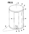
- the hull 10 ' is designed as a cylindrical body to its longitudinal axis 38, but provided with a flattening 34', which extends substantially over the extension of the hull 10 'in the direction of the longitudinal axis 38th extends.
- the hull is provided with a lid 30 'and a bottom 32', wherein the lid 30 'and the bottom 32' in the same manner as in the first embodiment may be connected to the hull 10 'or made of other material, for example made of plastic and otherwise fixed to the hull.
- the flattening 34 'does not extend completely to the respective end region 24', or 26 'of the hull 10', so that, for example, the respective end region 24 'or 26' of the hull 10 'can still be provided with a circular axis to the longitudinal axis 38 cross-section.
- the opening 80 ' is provided for performing the dispensing device 82, wherein the opening 80' with a closure unit 90 is closed, which is identical to the first Embodiment, so that in this regard is made in full content to the comments on the first embodiment.
- the lid 30 ' is preferably detachably connected to the fuselage 10', so that by removing the lid 30 ', the beverage sack 26 with the dispensing device 82 can be introduced into the interior 84 of the beverage keg and then the interior space 84 can be closed, the lid 30 'is so firmly connected to the hull 10' is that when you set up the beverage keg with the lid 30 'on a support surface of the lid 30' by the weight of the beverage bag 86 does not dissolve from the hull 10 '.
- Inserted into the opening 80 ' is a closure unit as a whole designated by 90' according to the third exemplary embodiment, which has an insert ring 92 which is formed in the same way as in the preceding embodiments.
- the insert ring 92 is a as a whole with 94 'designated closure element can be used, which is formed in the manufacturing state of the closure unit 90' so that it is connected via a tear-off 160 with the insert ring 92, namely the tear region 160 between the ring body 100th and the locking ring 106 of the closure element 94 'formed, wherein the locking ring 106 in the same manner as described in the first embodiment, in the through hole 110 of the insert ring 92 is pressed.
- latching ring 106 engages with its lateral surface 108 with the inner circumferential surface 112 of the passage opening 110 a latching connection, as likewise described in detail in connection with the first exemplary embodiment.
- the tear-off region 160 is designed such that in the production state, a side of the latching ring 106 opposite the closure body 104 'is connected to a side of the ring body 100 facing the support flange 98.
- the tear-off region 160 is dimensioned such that upon insertion of the closure unit 90 'into the opening 80', first the insert ring 92 can be pressed into the opening 80 'and then, for example by pressure on the closure element 94' and after the insert ring 92 has been fixed in that its bearing flange 98 rests laterally over the opening 80 'on the cover mirror 40, further pressure on the closure element 94 causes its locking ring 106 to latch in the passage opening 110 of the insert ring 92, after releasing the closure element in the tear-off region 160 94 'from the insert ring 92 has taken place.
- closure unit 90 serves to close the opening 80', such as in FIG FIG. 14 shown.
- the closure element 94' comprises, as in FIG. 14 a holding part 120 ', which is part of the closure unit 94', wherein the base 136 'is formed by a part of the closure body 104', while another part of the closure body 104 'closes the fork recess 138' of the holding part 120 'as the closure body part 162 wherein the closure body part 162 is connected to the holding part 120 'via a tear-off region 164.
- the closure body part 162 is formed so that this has a thinned edge region 166, which is connected to an edge region 168 of the holding part 120 'delimiting the fork recess 138'.
- the edge region 168 is formed, for example, by the base 136 'of the holding part 120'.
- the holding part 120 ' is provided with an approximately U-shaped front support rib 148' and, as already in FIGS. 12 and 13 shown, with a likewise inverted U-shaped formed rear support rib 146 ', which is also approximately U-shaped.
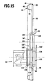
- the front support rib 148 ' has no curved contour, but in the same way as the rear support rib 146' has a roughly rectilinear supporting edge, which, as in FIG. 15 shown, abut the front collar flange 124 and rear collar flange 126 and thereby engage in the receptacle 130 on the collar 122 in order to fix the dispensing device 82.
- a mounting of the dispensing device 82 takes place in that when the closure element 94 'is seated on the insert ring 92, the closure body part 162 is pressed in the direction of the interior 84 and thus offers the possibility of the finger being inserted into the fork recess 138', which is thereby exposed to engage and release the closure element 94 'from its engagement with the insert ring 92.
- the now connected to the holding part 120 'dispensing device 82 can then be fixed by locking the locking ring 106 with the ring body 100 of the insert ring 92 turn the insert ring 92 and thereby simultaneously fixation of the dispensing device 82 relative to the insert ring 92 and thus also relative to the lid 30th ,
- the beverage can be taken out of the beverage bag 86 in the same way as described in detail in connection with the first embodiment.
- the third embodiment is formed in the same manner as the first embodiment, so that the same reference numerals are used for the same parts, so that in this respect the comments on the first embodiment can be fully incorporated by reference.
- the end region 24 "of the fuselage 10 ' is provided with a clamping collar 250 which, starting from the conical wall region 14, has a retracted end wall 254 which merges into an approximately cylindrically shaped clamping wall 252, the clamping wall 252 having a terminal curl 256 at the end.
- the cover 30 is similar to the cover of the preceding embodiments formed, which deviating from the preceding embodiments, the rising above the cover mirror 40 inner wall 44 "not tapered, but substantially cylindrical to the longitudinal axis 38, so that the inner wall 44" clamped to the clamping wall 252 may lie.
- the end wall 46 adjoining the inner wall 44 "and the outer wall 48 are shaped in the same way as in the first exemplary embodiment, and the curl 50 can be applied to the inwardly drawn end wall 254, whereby no fixation takes place by the curl 50 Fixing of the lid 30 "takes place on the clamping wall on the cylindrical clamping wall 252 adjacent inner wall 44" of the lid 30 ".
- Such a clamping of the lid 30 'on the clamping collar 250 has the advantage that so that the lid 30 "is easier to install and above all is easy to remove and thus the possibilities of use of the beverage keg according to the invention can be improved.
- the annular portion 42 is formed so that it overlaps the clamping collar 250 and can be invisible.
- closure unit 90 With regard to the design of the closure unit, it is possible to provide either a closure unit 90 according to the first embodiment or a closure unit 90 'according to the third embodiment.
Landscapes
- Engineering & Computer Science (AREA)
- Mechanical Engineering (AREA)
- Ceramic Engineering (AREA)
- Closures For Containers (AREA)
- Table Devices Or Equipment (AREA)
Applications Claiming Priority (2)
| Application Number | Priority Date | Filing Date | Title |
|---|---|---|---|
| DE102007056389 | 2007-11-16 | ||
| DE102007060725A DE102007060725A1 (de) | 2007-11-16 | 2007-12-07 | Fass |
Publications (3)
| Publication Number | Publication Date |
|---|---|
| EP2060497A2 true EP2060497A2 (fr) | 2009-05-20 |
| EP2060497A3 EP2060497A3 (fr) | 2009-06-03 |
| EP2060497B1 EP2060497B1 (fr) | 2012-06-20 |
Family
ID=40560857
Family Applications (1)
| Application Number | Title | Priority Date | Filing Date |
|---|---|---|---|
| EP08168454A Active EP2060497B1 (fr) | 2007-11-16 | 2008-11-06 | Tonneau |
Country Status (4)
| Country | Link |
|---|---|
| EP (1) | EP2060497B1 (fr) |
| DE (1) | DE102007060725A1 (fr) |
| DK (1) | DK2060497T3 (fr) |
| ES (1) | ES2388451T3 (fr) |
Families Citing this family (2)
| Publication number | Priority date | Publication date | Assignee | Title |
|---|---|---|---|---|
| CA2929204C (fr) | 2015-05-06 | 2020-11-17 | Mark J. Mckale | Appareil de recouvrement d'un baril |
| US11345505B2 (en) | 2020-08-19 | 2022-05-31 | Innovative Distilling Technologies, Inc. | Capped barrel system and methods |
Family Cites Families (6)
| Publication number | Priority date | Publication date | Assignee | Title |
|---|---|---|---|---|
| US3170586A (en) * | 1961-12-22 | 1965-02-23 | Firestone Tire & Rubber Co | Single walled metal container |
| GB1488618A (en) * | 1974-04-05 | 1977-10-12 | Mauser Kg | Cask |
| DE9011586U1 (de) * | 1990-08-09 | 1990-10-25 | Mauser-Werke GmbH, 5040 Brühl | Konisches Weithals-Stahlfaß |
| DE9408722U1 (de) * | 1994-05-27 | 1994-09-29 | Mauser-Werke GmbH, 50321 Brühl | Palletierbares L-Ringfaß |
| DE19641172C2 (de) * | 1996-10-08 | 2000-07-13 | Schuetz Werke Gmbh Co Kg | Mehrwegfaß aus Metallblech |
| DE29719429U1 (de) * | 1997-11-03 | 1998-04-30 | Trautner, Manfred, Dipl.-Ing., 21339 Lüneburg | Deckelfaß aus Kunststoff |
-
2007
- 2007-12-07 DE DE102007060725A patent/DE102007060725A1/de not_active Withdrawn
-
2008
- 2008-11-06 EP EP08168454A patent/EP2060497B1/fr active Active
- 2008-11-06 DK DK08168454.0T patent/DK2060497T3/da active
- 2008-11-06 ES ES08168454T patent/ES2388451T3/es active Active
Also Published As
| Publication number | Publication date |
|---|---|
| DE102007060725A1 (de) | 2009-05-20 |
| EP2060497A3 (fr) | 2009-06-03 |
| ES2388451T3 (es) | 2012-10-15 |
| DK2060497T3 (da) | 2012-08-27 |
| EP2060497B1 (fr) | 2012-06-20 |
Similar Documents
| Publication | Publication Date | Title |
|---|---|---|
| DE102012007642B4 (de) | Verschlussstopfen für einen Getränkebehälter | |
| EP2285703B1 (fr) | Bouchon tire-pousse pour un contenant à boisson | |
| EP2575566A1 (fr) | Dispositif d'infusion destiné à la lixiviation d'une dosette, procédé de fonctionnement d'un dispositif d'infusion et utilisation d'un dispositif d'infusion | |
| DE2920159A1 (de) | Trinkhilfsvorrichtung fuer getraenkedosen | |
| EP1792657A1 (fr) | Récipient avec couvercle | |
| EP2286703A2 (fr) | Pot de chambre, notamment pour enfants en bas-âge | |
| EP2060497B1 (fr) | Tonneau | |
| DE102009025316B4 (de) | Vorrichtung zum Öffnen und Verschließen eines Getränkebehälters mit hohem Innendruck | |
| EP2872417A2 (fr) | Canette, dispositif de support et procédé pour produire une canette | |
| DE102013104226B4 (de) | Wiederverschließbare Dosenstirnwand, Stirnwandeinheit und Dose | |
| DE102007059150A1 (de) | Tankeinfüllbereich eines Kraftfahrzeuges | |
| EP2470466B1 (fr) | Récipient jetable avec dispositif de fixation de raccord | |
| EP2941989B1 (fr) | Système de prélèvement pour distributeur d'essuie-mains | |
| DE102012003693A1 (de) | Tragevorrichtung für ein Fässchen | |
| DE102016008168A1 (de) | Trinkgefäß und Befüllvorrichtung zum automatischen Befüllen eines Trinkgefäßes | |
| EP1847467A1 (fr) | Bouchon pour un récipient | |
| DE3123381C2 (de) | Kapselabnehmer | |
| DE2246277A1 (de) | Behaelterverschluss | |
| DE102012222403B3 (de) | Verschließbarer Behälter | |
| DE102009054192A1 (de) | Behälter zur Aufnahme eines mit einer Flüssigkeit gefüllten Beutels | |
| WO2022053429A1 (fr) | Récipient pourvu d'un bord étanche | |
| DE10131694B4 (de) | Kabelausziehöffnung | |
| DE2806759C3 (de) | Spundlochverschluß für einen Druckbehälter | |
| EP1682809A1 (fr) | Raccordement par emboitement pour conduites et tuyaux, a bague d'etancheite a face oblique | |
| WO2017129176A1 (fr) | Dispositif de fermeture de récipients |
Legal Events
| Date | Code | Title | Description |
|---|---|---|---|
| PUAI | Public reference made under article 153(3) epc to a published international application that has entered the european phase |
Free format text: ORIGINAL CODE: 0009012 |
|
| PUAL | Search report despatched |
Free format text: ORIGINAL CODE: 0009013 |
|
| AK | Designated contracting states |
Kind code of ref document: A2 Designated state(s): AT BE BG CH CY CZ DE DK EE ES FI FR GB GR HR HU IE IS IT LI LT LU LV MC MT NL NO PL PT RO SE SI SK TR |
|
| AX | Request for extension of the european patent |
Extension state: AL BA MK RS |
|
| AK | Designated contracting states |
Kind code of ref document: A3 Designated state(s): AT BE BG CH CY CZ DE DK EE ES FI FR GB GR HR HU IE IS IT LI LT LU LV MC MT NL NO PL PT RO SE SI SK TR |
|
| AX | Request for extension of the european patent |
Extension state: AL BA MK RS |
|
| 17P | Request for examination filed |
Effective date: 20091203 |
|
| 17Q | First examination report despatched |
Effective date: 20100105 |
|
| AKX | Designation fees paid |
Designated state(s): AT BE BG CH CY CZ DE DK EE ES FI FR GB GR HR HU IE IS IT LI LT LU LV MC MT NL NO PL PT RO SE SI SK TR |
|
| GRAP | Despatch of communication of intention to grant a patent |
Free format text: ORIGINAL CODE: EPIDOSNIGR1 |
|
| GRAS | Grant fee paid |
Free format text: ORIGINAL CODE: EPIDOSNIGR3 |
|
| RAP1 | Party data changed (applicant data changed or rights of an application transferred) |
Owner name: JULIUS KLEEMANN GMBH & CO. KG |
|
| GRAA | (expected) grant |
Free format text: ORIGINAL CODE: 0009210 |
|
| AK | Designated contracting states |
Kind code of ref document: B1 Designated state(s): AT BE BG CH CY CZ DE DK EE ES FI FR GB GR HR HU IE IS IT LI LT LU LV MC MT NL NO PL PT RO SE SI SK TR |
|
| REG | Reference to a national code |
Ref country code: GB Ref legal event code: FG4D Free format text: NOT ENGLISH |
|
| REG | Reference to a national code |
Ref country code: CH Ref legal event code: EP |
|
| REG | Reference to a national code |
Ref country code: CH Ref legal event code: NV Representative=s name: KIRKER & CIE S.A. |
|
| REG | Reference to a national code |
Ref country code: AT Ref legal event code: REF Ref document number: 562937 Country of ref document: AT Kind code of ref document: T Effective date: 20120715 |
|
| REG | Reference to a national code |
Ref country code: IE Ref legal event code: FG4D Free format text: LANGUAGE OF EP DOCUMENT: GERMAN |
|
| REG | Reference to a national code |
Ref country code: DE Ref legal event code: R096 Ref document number: 502008007470 Country of ref document: DE Effective date: 20120816 |
|
| REG | Reference to a national code |
Ref country code: DK Ref legal event code: T3 |
|
| REG | Reference to a national code |
Ref country code: NL Ref legal event code: T3 |
|
| REG | Reference to a national code |
Ref country code: NO Ref legal event code: T2 Effective date: 20120620 |
|
| REG | Reference to a national code |
Ref country code: SE Ref legal event code: TRGR |
|
| REG | Reference to a national code |
Ref country code: ES Ref legal event code: FG2A Ref document number: 2388451 Country of ref document: ES Kind code of ref document: T3 Effective date: 20121015 |
|
| PG25 | Lapsed in a contracting state [announced via postgrant information from national office to epo] |
Ref country code: LT Free format text: LAPSE BECAUSE OF FAILURE TO SUBMIT A TRANSLATION OF THE DESCRIPTION OR TO PAY THE FEE WITHIN THE PRESCRIBED TIME-LIMIT Effective date: 20120620 |
|
| REG | Reference to a national code |
Ref country code: LT Ref legal event code: MG4D Effective date: 20120620 |
|
| PG25 | Lapsed in a contracting state [announced via postgrant information from national office to epo] |
Ref country code: SI Free format text: LAPSE BECAUSE OF FAILURE TO SUBMIT A TRANSLATION OF THE DESCRIPTION OR TO PAY THE FEE WITHIN THE PRESCRIBED TIME-LIMIT Effective date: 20120620 Ref country code: GR Free format text: LAPSE BECAUSE OF FAILURE TO SUBMIT A TRANSLATION OF THE DESCRIPTION OR TO PAY THE FEE WITHIN THE PRESCRIBED TIME-LIMIT Effective date: 20120921 Ref country code: LV Free format text: LAPSE BECAUSE OF FAILURE TO SUBMIT A TRANSLATION OF THE DESCRIPTION OR TO PAY THE FEE WITHIN THE PRESCRIBED TIME-LIMIT Effective date: 20120620 Ref country code: HR Free format text: LAPSE BECAUSE OF FAILURE TO SUBMIT A TRANSLATION OF THE DESCRIPTION OR TO PAY THE FEE WITHIN THE PRESCRIBED TIME-LIMIT Effective date: 20120620 |
|
| PG25 | Lapsed in a contracting state [announced via postgrant information from national office to epo] |
Ref country code: CZ Free format text: LAPSE BECAUSE OF FAILURE TO SUBMIT A TRANSLATION OF THE DESCRIPTION OR TO PAY THE FEE WITHIN THE PRESCRIBED TIME-LIMIT Effective date: 20120620 Ref country code: IS Free format text: LAPSE BECAUSE OF FAILURE TO SUBMIT A TRANSLATION OF THE DESCRIPTION OR TO PAY THE FEE WITHIN THE PRESCRIBED TIME-LIMIT Effective date: 20121020 Ref country code: EE Free format text: LAPSE BECAUSE OF FAILURE TO SUBMIT A TRANSLATION OF THE DESCRIPTION OR TO PAY THE FEE WITHIN THE PRESCRIBED TIME-LIMIT Effective date: 20120620 Ref country code: CY Free format text: LAPSE BECAUSE OF FAILURE TO SUBMIT A TRANSLATION OF THE DESCRIPTION OR TO PAY THE FEE WITHIN THE PRESCRIBED TIME-LIMIT Effective date: 20120620 Ref country code: SK Free format text: LAPSE BECAUSE OF FAILURE TO SUBMIT A TRANSLATION OF THE DESCRIPTION OR TO PAY THE FEE WITHIN THE PRESCRIBED TIME-LIMIT Effective date: 20120620 Ref country code: RO Free format text: LAPSE BECAUSE OF FAILURE TO SUBMIT A TRANSLATION OF THE DESCRIPTION OR TO PAY THE FEE WITHIN THE PRESCRIBED TIME-LIMIT Effective date: 20120620 |
|
| PG25 | Lapsed in a contracting state [announced via postgrant information from national office to epo] |
Ref country code: PL Free format text: LAPSE BECAUSE OF FAILURE TO SUBMIT A TRANSLATION OF THE DESCRIPTION OR TO PAY THE FEE WITHIN THE PRESCRIBED TIME-LIMIT Effective date: 20120620 Ref country code: PT Free format text: LAPSE BECAUSE OF FAILURE TO SUBMIT A TRANSLATION OF THE DESCRIPTION OR TO PAY THE FEE WITHIN THE PRESCRIBED TIME-LIMIT Effective date: 20121022 |
|
| PLBE | No opposition filed within time limit |
Free format text: ORIGINAL CODE: 0009261 |
|
| STAA | Information on the status of an ep patent application or granted ep patent |
Free format text: STATUS: NO OPPOSITION FILED WITHIN TIME LIMIT |
|
| 26N | No opposition filed |
Effective date: 20130321 |
|
| REG | Reference to a national code |
Ref country code: DE Ref legal event code: R097 Ref document number: 502008007470 Country of ref document: DE Effective date: 20130321 |
|
| PG25 | Lapsed in a contracting state [announced via postgrant information from national office to epo] |
Ref country code: BG Free format text: LAPSE BECAUSE OF FAILURE TO SUBMIT A TRANSLATION OF THE DESCRIPTION OR TO PAY THE FEE WITHIN THE PRESCRIBED TIME-LIMIT Effective date: 20120920 |
|
| REG | Reference to a national code |
Ref country code: IE Ref legal event code: MM4A |
|
| PG25 | Lapsed in a contracting state [announced via postgrant information from national office to epo] |
Ref country code: IE Free format text: LAPSE BECAUSE OF NON-PAYMENT OF DUE FEES Effective date: 20121106 |
|
| PG25 | Lapsed in a contracting state [announced via postgrant information from national office to epo] |
Ref country code: MT Free format text: LAPSE BECAUSE OF FAILURE TO SUBMIT A TRANSLATION OF THE DESCRIPTION OR TO PAY THE FEE WITHIN THE PRESCRIBED TIME-LIMIT Effective date: 20120620 |
|
| PG25 | Lapsed in a contracting state [announced via postgrant information from national office to epo] |
Ref country code: TR Free format text: LAPSE BECAUSE OF FAILURE TO SUBMIT A TRANSLATION OF THE DESCRIPTION OR TO PAY THE FEE WITHIN THE PRESCRIBED TIME-LIMIT Effective date: 20120620 |
|
| PG25 | Lapsed in a contracting state [announced via postgrant information from national office to epo] |
Ref country code: HU Free format text: LAPSE BECAUSE OF FAILURE TO SUBMIT A TRANSLATION OF THE DESCRIPTION OR TO PAY THE FEE WITHIN THE PRESCRIBED TIME-LIMIT Effective date: 20081106 |
|
| REG | Reference to a national code |
Ref country code: DE Ref legal event code: R082 Ref document number: 502008007470 Country of ref document: DE Representative=s name: HOEGER, STELLRECHT & PARTNER PATENTANWAELTE MB, DE |
|
| REG | Reference to a national code |
Ref country code: FR Ref legal event code: PLFP Year of fee payment: 8 |
|
| REG | Reference to a national code |
Ref country code: FR Ref legal event code: PLFP Year of fee payment: 9 |
|
| REG | Reference to a national code |
Ref country code: DE Ref legal event code: R082 Ref document number: 502008007470 Country of ref document: DE Representative=s name: HOEGER, STELLRECHT & PARTNER PATENTANWAELTE MB, DE Ref country code: DE Ref legal event code: R081 Ref document number: 502008007470 Country of ref document: DE Owner name: JULIUS KLEEMANN GMBH & CO. KG, DE Free format text: FORMER OWNER: JULIUS KLEEMANN GMBH & CO., 63791 KARLSTEIN, DE |
|
| REG | Reference to a national code |
Ref country code: FR Ref legal event code: PLFP Year of fee payment: 10 |
|
| REG | Reference to a national code |
Ref country code: FR Ref legal event code: PLFP Year of fee payment: 11 |
|
| REG | Reference to a national code |
Ref country code: DE Ref legal event code: R082 Ref document number: 502008007470 Country of ref document: DE Representative=s name: HOEGER, STELLRECHT & PARTNER PATENTANWAELTE MB, DE |
|
| P01 | Opt-out of the competence of the unified patent court (upc) registered |
Effective date: 20230517 |
|
| PGFP | Annual fee paid to national office [announced via postgrant information from national office to epo] |
Ref country code: NL Payment date: 20250912 Year of fee payment: 18 |
|
| PGFP | Annual fee paid to national office [announced via postgrant information from national office to epo] |
Ref country code: GB Payment date: 20250918 Year of fee payment: 18 |
|
| PGFP | Annual fee paid to national office [announced via postgrant information from national office to epo] |
Ref country code: FR Payment date: 20250908 Year of fee payment: 18 |
|
| PGFP | Annual fee paid to national office [announced via postgrant information from national office to epo] |
Ref country code: SE Payment date: 20250910 Year of fee payment: 18 |
|
| PGFP | Annual fee paid to national office [announced via postgrant information from national office to epo] |
Ref country code: LU Payment date: 20251027 Year of fee payment: 18 |
|
| REG | Reference to a national code |
Ref country code: CH Ref legal event code: U11 Free format text: ST27 STATUS EVENT CODE: U-0-0-U10-U11 (AS PROVIDED BY THE NATIONAL OFFICE) Effective date: 20251201 |
|
| PGFP | Annual fee paid to national office [announced via postgrant information from national office to epo] |
Ref country code: DE Payment date: 20251124 Year of fee payment: 18 |
|
| PGFP | Annual fee paid to national office [announced via postgrant information from national office to epo] |
Ref country code: NO Payment date: 20251113 Year of fee payment: 18 Ref country code: MC Payment date: 20251028 Year of fee payment: 18 |
|
| PGFP | Annual fee paid to national office [announced via postgrant information from national office to epo] |
Ref country code: AT Payment date: 20251027 Year of fee payment: 18 |
|
| PGFP | Annual fee paid to national office [announced via postgrant information from national office to epo] |
Ref country code: IT Payment date: 20251022 Year of fee payment: 18 Ref country code: FI Payment date: 20251113 Year of fee payment: 18 Ref country code: DK Payment date: 20251112 Year of fee payment: 18 |
|
| PGFP | Annual fee paid to national office [announced via postgrant information from national office to epo] |
Ref country code: BE Payment date: 20251003 Year of fee payment: 18 |
|
| PGFP | Annual fee paid to national office [announced via postgrant information from national office to epo] |
Ref country code: CH Payment date: 20251201 Year of fee payment: 18 |
|
| PGFP | Annual fee paid to national office [announced via postgrant information from national office to epo] |
Ref country code: ES Payment date: 20251212 Year of fee payment: 18 |