EP2060502A1 - Behälter - Google Patents
Behälter Download PDFInfo
- Publication number
- EP2060502A1 EP2060502A1 EP07388082A EP07388082A EP2060502A1 EP 2060502 A1 EP2060502 A1 EP 2060502A1 EP 07388082 A EP07388082 A EP 07388082A EP 07388082 A EP07388082 A EP 07388082A EP 2060502 A1 EP2060502 A1 EP 2060502A1
- Authority
- EP
- European Patent Office
- Prior art keywords
- discharge portion
- lid
- container
- bistable
- discharge
- Prior art date
- Legal status (The legal status is an assumption and is not a legal conclusion. Google has not performed a legal analysis and makes no representation as to the accuracy of the status listed.)
- Withdrawn
Links
Images




Classifications
-
- B—PERFORMING OPERATIONS; TRANSPORTING
- B65—CONVEYING; PACKING; STORING; HANDLING THIN OR FILAMENTARY MATERIAL
- B65D—CONTAINERS FOR STORAGE OR TRANSPORT OF ARTICLES OR MATERIALS, e.g. BAGS, BARRELS, BOTTLES, BOXES, CANS, CARTONS, CRATES, DRUMS, JARS, TANKS, HOPPERS, FORWARDING CONTAINERS; ACCESSORIES, CLOSURES, OR FITTINGS THEREFOR; PACKAGING ELEMENTS; PACKAGES
- B65D11/00—Containers having bodies formed by interconnecting or uniting two or more rigid, or substantially rigid, components made wholly or mainly of plastics material
- B65D11/02—Containers having bodies formed by interconnecting or uniting two or more rigid, or substantially rigid, components made wholly or mainly of plastics material of curved cross-section
- B65D11/06—Drums or barrels
- B65D11/08—Arrangements of filling or discharging apertures
-
- B—PERFORMING OPERATIONS; TRANSPORTING
- B65—CONVEYING; PACKING; STORING; HANDLING THIN OR FILAMENTARY MATERIAL
- B65D—CONTAINERS FOR STORAGE OR TRANSPORT OF ARTICLES OR MATERIALS, e.g. BAGS, BARRELS, BOTTLES, BOXES, CANS, CARTONS, CRATES, DRUMS, JARS, TANKS, HOPPERS, FORWARDING CONTAINERS; ACCESSORIES, CLOSURES, OR FITTINGS THEREFOR; PACKAGING ELEMENTS; PACKAGES
- B65D21/00—Nestable, stackable or joinable containers; Containers of variable capacity
- B65D21/02—Containers specially shaped, or provided with fittings or attachments, to facilitate nesting, stacking, or joining together
- B65D21/0209—Containers specially shaped, or provided with fittings or attachments, to facilitate nesting, stacking, or joining together stackable or joined together one-upon-the-other in the upright or upside-down position
- B65D21/0217—Containers with a closure presenting stacking elements
- B65D21/022—Containers with a closure presenting stacking elements the bottom presenting projecting peripheral elements receiving or surrounding the closure or peripheral elements projecting therefrom
-
- B—PERFORMING OPERATIONS; TRANSPORTING
- B65—CONVEYING; PACKING; STORING; HANDLING THIN OR FILAMENTARY MATERIAL
- B65D—CONTAINERS FOR STORAGE OR TRANSPORT OF ARTICLES OR MATERIALS, e.g. BAGS, BARRELS, BOTTLES, BOXES, CANS, CARTONS, CRATES, DRUMS, JARS, TANKS, HOPPERS, FORWARDING CONTAINERS; ACCESSORIES, CLOSURES, OR FITTINGS THEREFOR; PACKAGING ELEMENTS; PACKAGES
- B65D21/00—Nestable, stackable or joinable containers; Containers of variable capacity
- B65D21/02—Containers specially shaped, or provided with fittings or attachments, to facilitate nesting, stacking, or joining together
- B65D21/0209—Containers specially shaped, or provided with fittings or attachments, to facilitate nesting, stacking, or joining together stackable or joined together one-upon-the-other in the upright or upside-down position
- B65D21/023—Closed containers provided with local cooperating elements in the top and bottom surfaces, e.g. projection and recess
- B65D21/0231—Bottles, canisters or jars whereby the neck or handle project into a cooperating cavity in the bottom
-
- B—PERFORMING OPERATIONS; TRANSPORTING
- B65—CONVEYING; PACKING; STORING; HANDLING THIN OR FILAMENTARY MATERIAL
- B65D—CONTAINERS FOR STORAGE OR TRANSPORT OF ARTICLES OR MATERIALS, e.g. BAGS, BARRELS, BOTTLES, BOXES, CANS, CARTONS, CRATES, DRUMS, JARS, TANKS, HOPPERS, FORWARDING CONTAINERS; ACCESSORIES, CLOSURES, OR FITTINGS THEREFOR; PACKAGING ELEMENTS; PACKAGES
- B65D47/00—Closures with filling and discharging, or with discharging, devices
- B65D47/04—Closures with discharging devices other than pumps
- B65D47/06—Closures with discharging devices other than pumps with pouring spouts or tubes; with discharge nozzles or passages
- B65D47/061—Closures with discharging devices other than pumps with pouring spouts or tubes; with discharge nozzles or passages with telescopic, retractable or reversible spouts, tubes or nozzles
- B65D47/063—Closures with discharging devices other than pumps with pouring spouts or tubes; with discharge nozzles or passages with telescopic, retractable or reversible spouts, tubes or nozzles with flexible parts
-
- B—PERFORMING OPERATIONS; TRANSPORTING
- B65—CONVEYING; PACKING; STORING; HANDLING THIN OR FILAMENTARY MATERIAL
- B65D—CONTAINERS FOR STORAGE OR TRANSPORT OF ARTICLES OR MATERIALS, e.g. BAGS, BARRELS, BOTTLES, BOXES, CANS, CARTONS, CRATES, DRUMS, JARS, TANKS, HOPPERS, FORWARDING CONTAINERS; ACCESSORIES, CLOSURES, OR FITTINGS THEREFOR; PACKAGING ELEMENTS; PACKAGES
- B65D2543/00—Lids or covers essentially for box-like containers
- B65D2543/00009—Details of lids or covers for rigid or semi-rigid containers
- B65D2543/00018—Overall construction of the lid
- B65D2543/00027—Stackable lids or covers
-
- B—PERFORMING OPERATIONS; TRANSPORTING
- B65—CONVEYING; PACKING; STORING; HANDLING THIN OR FILAMENTARY MATERIAL
- B65D—CONTAINERS FOR STORAGE OR TRANSPORT OF ARTICLES OR MATERIALS, e.g. BAGS, BARRELS, BOTTLES, BOXES, CANS, CARTONS, CRATES, DRUMS, JARS, TANKS, HOPPERS, FORWARDING CONTAINERS; ACCESSORIES, CLOSURES, OR FITTINGS THEREFOR; PACKAGING ELEMENTS; PACKAGES
- B65D2543/00—Lids or covers essentially for box-like containers
- B65D2543/00009—Details of lids or covers for rigid or semi-rigid containers
- B65D2543/00018—Overall construction of the lid
- B65D2543/00064—Shape of the outer periphery
- B65D2543/00074—Shape of the outer periphery curved
- B65D2543/00092—Shape of the outer periphery curved circular
-
- B—PERFORMING OPERATIONS; TRANSPORTING
- B65—CONVEYING; PACKING; STORING; HANDLING THIN OR FILAMENTARY MATERIAL
- B65D—CONTAINERS FOR STORAGE OR TRANSPORT OF ARTICLES OR MATERIALS, e.g. BAGS, BARRELS, BOTTLES, BOXES, CANS, CARTONS, CRATES, DRUMS, JARS, TANKS, HOPPERS, FORWARDING CONTAINERS; ACCESSORIES, CLOSURES, OR FITTINGS THEREFOR; PACKAGING ELEMENTS; PACKAGES
- B65D2543/00—Lids or covers essentially for box-like containers
- B65D2543/00009—Details of lids or covers for rigid or semi-rigid containers
- B65D2543/00018—Overall construction of the lid
- B65D2543/00259—Materials used
- B65D2543/00296—Plastic
-
- B—PERFORMING OPERATIONS; TRANSPORTING
- B65—CONVEYING; PACKING; STORING; HANDLING THIN OR FILAMENTARY MATERIAL
- B65D—CONTAINERS FOR STORAGE OR TRANSPORT OF ARTICLES OR MATERIALS, e.g. BAGS, BARRELS, BOTTLES, BOXES, CANS, CARTONS, CRATES, DRUMS, JARS, TANKS, HOPPERS, FORWARDING CONTAINERS; ACCESSORIES, CLOSURES, OR FITTINGS THEREFOR; PACKAGING ELEMENTS; PACKAGES
- B65D2543/00—Lids or covers essentially for box-like containers
- B65D2543/00009—Details of lids or covers for rigid or semi-rigid containers
- B65D2543/00342—Central part of the lid
- B65D2543/0037—Flexible or deformable
-
- B—PERFORMING OPERATIONS; TRANSPORTING
- B65—CONVEYING; PACKING; STORING; HANDLING THIN OR FILAMENTARY MATERIAL
- B65D—CONTAINERS FOR STORAGE OR TRANSPORT OF ARTICLES OR MATERIALS, e.g. BAGS, BARRELS, BOTTLES, BOXES, CANS, CARTONS, CRATES, DRUMS, JARS, TANKS, HOPPERS, FORWARDING CONTAINERS; ACCESSORIES, CLOSURES, OR FITTINGS THEREFOR; PACKAGING ELEMENTS; PACKAGES
- B65D2543/00—Lids or covers essentially for box-like containers
- B65D2543/00009—Details of lids or covers for rigid or semi-rigid containers
- B65D2543/00342—Central part of the lid
- B65D2543/00398—Reinforcing ribs in the central part of the closure
- B65D2543/00407—Reinforcing ribs in the central part of the closure radial
-
- B—PERFORMING OPERATIONS; TRANSPORTING
- B65—CONVEYING; PACKING; STORING; HANDLING THIN OR FILAMENTARY MATERIAL
- B65D—CONTAINERS FOR STORAGE OR TRANSPORT OF ARTICLES OR MATERIALS, e.g. BAGS, BARRELS, BOTTLES, BOXES, CANS, CARTONS, CRATES, DRUMS, JARS, TANKS, HOPPERS, FORWARDING CONTAINERS; ACCESSORIES, CLOSURES, OR FITTINGS THEREFOR; PACKAGING ELEMENTS; PACKAGES
- B65D2543/00—Lids or covers essentially for box-like containers
- B65D2543/00009—Details of lids or covers for rigid or semi-rigid containers
- B65D2543/00444—Contact between the container and the lid
- B65D2543/00481—Contact between the container and the lid on the inside or the outside of the container
- B65D2543/0049—Contact between the container and the lid on the inside or the outside of the container on the inside, or a part turned to the inside of the mouth of the container
- B65D2543/005—Contact between the container and the lid on the inside or the outside of the container on the inside, or a part turned to the inside of the mouth of the container both cup and skirt
-
- B—PERFORMING OPERATIONS; TRANSPORTING
- B65—CONVEYING; PACKING; STORING; HANDLING THIN OR FILAMENTARY MATERIAL
- B65D—CONTAINERS FOR STORAGE OR TRANSPORT OF ARTICLES OR MATERIALS, e.g. BAGS, BARRELS, BOTTLES, BOXES, CANS, CARTONS, CRATES, DRUMS, JARS, TANKS, HOPPERS, FORWARDING CONTAINERS; ACCESSORIES, CLOSURES, OR FITTINGS THEREFOR; PACKAGING ELEMENTS; PACKAGES
- B65D2543/00—Lids or covers essentially for box-like containers
- B65D2543/00009—Details of lids or covers for rigid or semi-rigid containers
- B65D2543/00444—Contact between the container and the lid
- B65D2543/00481—Contact between the container and the lid on the inside or the outside of the container
- B65D2543/00537—Contact between the container and the lid on the inside or the outside of the container on the outside, or a part turned to the outside of the mouth of the container
-
- B—PERFORMING OPERATIONS; TRANSPORTING
- B65—CONVEYING; PACKING; STORING; HANDLING THIN OR FILAMENTARY MATERIAL
- B65D—CONTAINERS FOR STORAGE OR TRANSPORT OF ARTICLES OR MATERIALS, e.g. BAGS, BARRELS, BOTTLES, BOXES, CANS, CARTONS, CRATES, DRUMS, JARS, TANKS, HOPPERS, FORWARDING CONTAINERS; ACCESSORIES, CLOSURES, OR FITTINGS THEREFOR; PACKAGING ELEMENTS; PACKAGES
- B65D2543/00—Lids or covers essentially for box-like containers
- B65D2543/00009—Details of lids or covers for rigid or semi-rigid containers
- B65D2543/00444—Contact between the container and the lid
- B65D2543/00481—Contact between the container and the lid on the inside or the outside of the container
- B65D2543/00555—Contact between the container and the lid on the inside or the outside of the container on both the inside and the outside
-
- B—PERFORMING OPERATIONS; TRANSPORTING
- B65—CONVEYING; PACKING; STORING; HANDLING THIN OR FILAMENTARY MATERIAL
- B65D—CONTAINERS FOR STORAGE OR TRANSPORT OF ARTICLES OR MATERIALS, e.g. BAGS, BARRELS, BOTTLES, BOXES, CANS, CARTONS, CRATES, DRUMS, JARS, TANKS, HOPPERS, FORWARDING CONTAINERS; ACCESSORIES, CLOSURES, OR FITTINGS THEREFOR; PACKAGING ELEMENTS; PACKAGES
- B65D2543/00—Lids or covers essentially for box-like containers
- B65D2543/00009—Details of lids or covers for rigid or semi-rigid containers
- B65D2543/00444—Contact between the container and the lid
- B65D2543/00592—Snapping means
- B65D2543/00601—Snapping means on the container
- B65D2543/00611—Profiles
- B65D2543/00629—Massive bead
-
- B—PERFORMING OPERATIONS; TRANSPORTING
- B65—CONVEYING; PACKING; STORING; HANDLING THIN OR FILAMENTARY MATERIAL
- B65D—CONTAINERS FOR STORAGE OR TRANSPORT OF ARTICLES OR MATERIALS, e.g. BAGS, BARRELS, BOTTLES, BOXES, CANS, CARTONS, CRATES, DRUMS, JARS, TANKS, HOPPERS, FORWARDING CONTAINERS; ACCESSORIES, CLOSURES, OR FITTINGS THEREFOR; PACKAGING ELEMENTS; PACKAGES
- B65D2543/00—Lids or covers essentially for box-like containers
- B65D2543/00009—Details of lids or covers for rigid or semi-rigid containers
- B65D2543/00444—Contact between the container and the lid
- B65D2543/00592—Snapping means
- B65D2543/00712—Snapping means on the lid
- B65D2543/00722—Profiles
- B65D2543/0074—Massive bead
Definitions
- the present invention relates to a container according to claim 1 and to a lid according to claim 17.
- Containers having the structural elements defined in the preamble of claim 1 are generally disclosed in DE 85 18 074 U and may be used for dispensing a material held in the container.
- discharge is controlled through the bistable part of the lid assuming a retracted or advanced position, the bistable part of the lid having discharge apertures.
- the present invention has for its object to provide for a container which may be stacked without damage to a discharge portion of the container, which provides for a sealed environment of the contents of the container, and which by its structure may assist in emptying of the container when the container is turned upside down.
- the container includes a lid with a discharge portion and an elastically flexible bistable portion that may be annular and that allows the discharge portion to assume a retracted position and an advanced position, the bistable portion extending around the discharge portion.
- the discharge portion includes a stopper operable independent of the position of the discharge portion to selectively allow for or prevent discharge of the contents of the container through the discharge portion.
- the container according to the invention is of particular use where the content held within the container is of high value such that a complete or near complete discharge of all the content must be ensured during emptying. This is achieved in the surface of the bistable portion that faces the inside of the container preferably acting in the advanced position of the discharge portion as a funnel.
- the funnel surface along which the content of the container flows towards the discharge portion provides, by preferably being even, for a minimum of spots where any part of the content may be trapped during the emptying process.
- the discharge portion includes a through-going opening with a valve housing including a valve structure mounted therein.
- the discharge portion may include a peripheral wall structure connected to the bistable surrounding portion and delimiting the through-going opening; the valve housing being mounted to the peripheral wall structure.
- the container is designed such that when the container is placed on another container according to the invention it will be supported by the lid of that container, preferably adjacent and along a peripheral rim portion of the lid of that container.
- the bottom of the container is preferably geometrically configured to receive at least a part of the stopper of the container on which it is placed in the retracted position but not in the advanced position of the discharge portion of the latter container.
- the lid of the container preferably is essentially circular in shape when viewed from above; other shapes such as oval, square or near square shapes may, however, also be envisaged, with the container wall having a corresponding shape to allow for the lid to be mounted thereon.
- the discharge portion is located coincident with the central axis of the peripheral wall of the container. This allows for the lid to be designed as a rotationally symmetrical or near-rotationally symmetrical plastics structure.
- Fig. 1 shows a plastics container 1, preferably made of polypropylene PP or PE, which has a first end and an opposite second end.
- a cylindrical or conical peripheral wall 5 extends from the first end to the second end.
- a lid 10 of the container 1 defines the first end while a bottom member 8 defines the second end.
- the lid 10 is circular or essentially circular as seen from above and is mounted onto the peripheral wall 5 by snap engagement; however, a screw-thread connection may be provided for. In a less preferred embodiment, the lid 10 may be non-removably mounted.
- the bottom member 8 is preferably integrally moulded with the wall 5, such as in an injection molding process, and reinforcing ribs 2 are preferably a part of the bottom member 8.
- the content of the container 1 is schematically indicated in hatched line and designated numeral 100.
- the container 1 may be used for holding any material capable of flowing, liquid or granular.
- the container 1 is shown in fig. 1 in an upright position in which the container is typically transported to the end-user in a stack comprising identical containers arranged on a pallet. After delivery the container 1 is preferably placed in an inverted position with the bottom member 8 facing upwards to allow for a discharge, preferably by gravity, of the contents through a central discharge portion 15 of the lid 10 to be discussed in further details below. It is noted that the dimensions of the container may vary within a broad range; typically, however, the container may have a diameter within the range of 30 cm - 70 cm and a height defined by the wall 5 of 60 cm - 120 cm.
- the bottom member 8 may be flat, or preferably vaulted, preferably with a central recess, as shown.
- the lid 10 has a shape resembling a circular vaulted or dome-shaped disc with the centre thereof coincident with the axis C of the peripheral cylindrical or conical wall 5. Moreover, the lid 10 has a central discharge portion 15 which includes a peripheral preferably cylindrical or conical wall structure 18 which delimits a through-going opening 16 in which is mounted a stopper 30. Although not preferred, the container may be filled through the through-going opening 16 after application of the lid 10 onto the rim of the wall 5 and before the stopper 30 is mounted.
- a tiny air vent may be provided to allow for a controlled in-take of air as required to assist in the emptying of the container 1.
- the air vent 22 should not permit discharge there-through of the granular or liquid contents 100 of the container 1.
- the stopper 30 is formed as a valve housing 31 that has a through-going passage and a valve structure for the controlled discharge of the contents of the container 1 through that passage; fig. 1 shows the stopper 30 before it is securely mounted to the wall structure 18 such as by snap-engagement.
- the stopper 30 may alternatively be a plug (not shown) inserted into the opening 16, or a lid (not shown) screwed or otherwise connected to the wall structure 18 so as to allow for controlled discharge of the contents 100 of the container by removal of the stopper 30.
- An annular elastically flexible lid portion 20 resembling the shape of a slightly vaulted cone surrounds the opening 16 and is integrally connected at its small radius side with the peripheral wall structure 18. Near the larger radius side of the annular portion 20 the lid 10 is connected to the rim of the container 1 wall 5.
- a bistable portion/structure is provided, and fig. 2 shows the lid 20 in the two shapes possible as result of the bistable structure, namely a first stable state indicated in broken line wherein the stopper (not shown) will be farthest from the bottom member 8, and another stable state wherein the portion 20 is inverted to assume the shape of a slightly vaulted cone such that the stopper 30 is retracted closer to the bottom member 8.
- a person may bring the stopper 30 to assume the advanced position from the retracted position by simply holding on to the rigid wall structure 18 and then applying an upward manual force resulting in the wall structure 18 popping up as the portion 20 is temporarily deformed to thereafter reassume the cone-like shape.
- the lid 10 may be brought to the advanced position by turning the container upside down so that the mass of contents 100 of the container 1 acting on the inside surface 25 of the lid 10 will force the lid 10 to assume the advanced position.
- the skilled person will realize that the force required to bring the lid from the one shape to the other may be affected by factors such as the thickness of the portion 20 and by the plastics material used for making the lid 10. It is noted that the lid 10 need not be applied to the wall 5 for the change of shape to be possible.
- the lid 10 and stopper 30 may be so designed that in the retracted position the tip of the stopper 30 lies below the imaginary line B about which the annular portion 20 moves to assume the one or the other shape whereby a flat surface pallet may be placed on top of the container 1 without damaging the tip of stopper 30.
- Fig. 2 shows an embodiment where in the retracted position the tip of the stopper 30 lies above line B and where the bottom member 8 is geometrically configured to be capable of receiving a part of the stopper 30 of a lower identical container of a stack when the discharge portion 15 with the stopper 30 is in the retracted position but not in the advanced position.
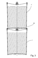
- Fig. 3 shows two such containers 1, 1' in a stacked relationship wherein each stopper 30 is in the retracted position.
- the upper container 1' rests against the lower level container 1 in the area of the wall 5 only, and through the selected geometric configuration of the bottom member 8 the stopper 30 lies confined and protected in the space below the bottom member 8 of the upper level container 1', preferably with the bottom member 8 distant from the stopper 30.
- the bottom member 8 is generally geometrically configured such that the stopper 30 of the lower container 1 is not nestable by the bottom member 8 of the upper level container 1' when in the advanced position. This allows for a high internal volume of the container useful for storing the contents.
- Fig. 4 shows the container 1 with the valve housing 31 in the advanced position and turned upside down, ready for being emptied by activation of the valve structure of valve housing 31.
- the container 1 is supported in the upside down position by a holder device (not shown), and activation of the valve to discharge the contents 100 may take place automatically when the container is placed in the holder device through the use of a one-way ball valve; the valve may, however, be of the type that is manually activatable, such as by having a tap whereby discharge of the contents 100 follows from the tap being manipulated as required.
- the inside surface 25 acting as a funnel whereby the contents of the container will run along surface 25 towards the outlet 30.
- the inside surface 25 is preferably smooth along the entire annular extension thereof, with no projecting irregularities, or as few projecting irregularities as possible.
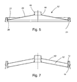
- Fig. 5 shows an enlarged cross-sectional view of the preferred embodiment of the circular lid 10' which is for snap-engagement with the rim 6 of the container 1 wall 5, as shown in fig. 6 .
- the lid 10' has a peripheral rim portion 21 integrally connected to a peripheral portion 27, along which the upper container 1' shown in fig. 3 is supported. Reinforcing ribs 26 may conveniently be provided to allow for a stable support of an overlying container 1' as shown in fig. 3 .
- the peripheral portion 27 is integrally connected with the annular bistable portion 20 which again is integrally connected with the peripheral wall structure 18.
- Ribs 19 and 26 at the small and large radius sides of portion 20 also control or restrict deformation of the wall structure 18 and rim portion 21 as the annular portion 20 is deformed to assume the two stable configurations.
- Fig. 7 shows two lids 10' in a stacked position. A peripheral edge 12 of rim portion 21 rests on the upper surface of the rim portion 21.
Landscapes
- Engineering & Computer Science (AREA)
- Mechanical Engineering (AREA)
- Closures For Containers (AREA)
Priority Applications (1)
| Application Number | Priority Date | Filing Date | Title |
|---|---|---|---|
| EP07388082A EP2060502A1 (de) | 2007-11-13 | 2007-11-13 | Behälter |
Applications Claiming Priority (1)
| Application Number | Priority Date | Filing Date | Title |
|---|---|---|---|
| EP07388082A EP2060502A1 (de) | 2007-11-13 | 2007-11-13 | Behälter |
Publications (1)
| Publication Number | Publication Date |
|---|---|
| EP2060502A1 true EP2060502A1 (de) | 2009-05-20 |
Family
ID=39186122
Family Applications (1)
| Application Number | Title | Priority Date | Filing Date |
|---|---|---|---|
| EP07388082A Withdrawn EP2060502A1 (de) | 2007-11-13 | 2007-11-13 | Behälter |
Country Status (1)
| Country | Link |
|---|---|
| EP (1) | EP2060502A1 (de) |
Cited By (2)
| Publication number | Priority date | Publication date | Assignee | Title |
|---|---|---|---|---|
| US20170247142A1 (en) * | 2016-02-26 | 2017-08-31 | Plastipak Packaging, Inc. | Stackable container with spout |
| WO2020009644A1 (en) * | 2018-07-05 | 2020-01-09 | Mölnlycke Health Care Ab | A fluid container |
Citations (6)
| Publication number | Priority date | Publication date | Assignee | Title |
|---|---|---|---|---|
| DE1087968B (de) * | 1957-06-04 | 1960-08-25 | Erich Golde Dipl Ing | Verschluss fuer eine mit einem Kanister, Fass od. ae. Behaelter verbindbare, trichterfoermige Ausgiesstuelle |
| US3326421A (en) * | 1965-11-12 | 1967-06-20 | Eastman Kodak Co | Retractable plastic bottle spout |
| DE8518074U1 (de) | 1985-06-21 | 1986-02-20 | Henkel KGaA, 4000 Düsseldorf | Einteiliger, wiederverschließbarer Streuverschluß |
| US4848601A (en) * | 1981-10-07 | 1989-07-18 | Tetra Pak Developpement S.A. | Packaging means for filling materials which are capable of flow, having a plastics cover |
| DE9213289U1 (de) * | 1992-10-02 | 1992-12-24 | Werner & Mertz Gmbh, 6500 Mainz | Nachfüllbehälter |
| DE4440513A1 (de) * | 1994-11-12 | 1996-05-15 | Stolz Heinrich Gmbh | Verschluß |
-
2007
- 2007-11-13 EP EP07388082A patent/EP2060502A1/de not_active Withdrawn
Patent Citations (6)
| Publication number | Priority date | Publication date | Assignee | Title |
|---|---|---|---|---|
| DE1087968B (de) * | 1957-06-04 | 1960-08-25 | Erich Golde Dipl Ing | Verschluss fuer eine mit einem Kanister, Fass od. ae. Behaelter verbindbare, trichterfoermige Ausgiesstuelle |
| US3326421A (en) * | 1965-11-12 | 1967-06-20 | Eastman Kodak Co | Retractable plastic bottle spout |
| US4848601A (en) * | 1981-10-07 | 1989-07-18 | Tetra Pak Developpement S.A. | Packaging means for filling materials which are capable of flow, having a plastics cover |
| DE8518074U1 (de) | 1985-06-21 | 1986-02-20 | Henkel KGaA, 4000 Düsseldorf | Einteiliger, wiederverschließbarer Streuverschluß |
| DE9213289U1 (de) * | 1992-10-02 | 1992-12-24 | Werner & Mertz Gmbh, 6500 Mainz | Nachfüllbehälter |
| DE4440513A1 (de) * | 1994-11-12 | 1996-05-15 | Stolz Heinrich Gmbh | Verschluß |
Cited By (4)
| Publication number | Priority date | Publication date | Assignee | Title |
|---|---|---|---|---|
| US20170247142A1 (en) * | 2016-02-26 | 2017-08-31 | Plastipak Packaging, Inc. | Stackable container with spout |
| US11034484B2 (en) * | 2016-02-26 | 2021-06-15 | Plastipak Packaging, Inc. | Stackable container with spout |
| WO2020009644A1 (en) * | 2018-07-05 | 2020-01-09 | Mölnlycke Health Care Ab | A fluid container |
| US11911340B2 (en) | 2018-07-05 | 2024-02-27 | Mölnlycke Health Care Ab | Fluid container |
Similar Documents
| Publication | Publication Date | Title |
|---|---|---|
| CN1934009B (zh) | 用于保持可流动产品的容器的罩盖 | |
| US4101044A (en) | Closure cap and support for holding a bottle of carbonated beverage in inverted position | |
| US7721774B2 (en) | Filling device for use with a container | |
| US8517228B2 (en) | Dispensing cap for a container | |
| EP1902971B1 (de) | Flüssigkeitsabgabevorrichtung und -gerät | |
| CA2573335A1 (en) | Closure with selectable dispensing orifices | |
| US20040217138A1 (en) | Dispenser with adjustable lateral powder flow | |
| JP5193785B2 (ja) | 詰め替え容器 | |
| US20120279968A1 (en) | Child Resistant Dosing Adapter Cap | |
| US5620662A (en) | Temporary liquid storage cavities in a centrifuge tube lid | |
| US6269983B1 (en) | Metered material dispenser | |
| WO2014181337A2 (en) | Retractable spout assemblies | |
| WO1998024697A1 (en) | Flow control cap | |
| US20100163583A1 (en) | Holder for Containing and Dispensing a Fluid | |
| CN106334342B (zh) | 用于存储和倾倒液体的组合件和液体处理系统 | |
| KR101497240B1 (ko) | 용기내부의 일정압력을 유지하는 안전마개 | |
| KR101560310B1 (ko) | 내용물 통과장치 및 이를 구비하는 포장용기 | |
| KR200493357Y1 (ko) | 이액 분리 저장이 가능한 앰플용기 | |
| US8056761B2 (en) | Pouring device | |
| JP7748828B2 (ja) | バルブ付き合成樹脂注出具 | |
| JP7705755B2 (ja) | バルブ付き合成樹脂注出具 | |
| JP6797678B2 (ja) | 注出容器 | |
| AU2004200197B2 (en) | Liquid Dispensing Container | |
| JP3180754U (ja) | 定量吐出キャップ | |
| CA1112209A (en) | Closure cap and support for holding a bottle of carbonated beverage in inverted position |
Legal Events
| Date | Code | Title | Description |
|---|---|---|---|
| PUAI | Public reference made under article 153(3) epc to a published international application that has entered the european phase |
Free format text: ORIGINAL CODE: 0009012 |
|
| AK | Designated contracting states |
Kind code of ref document: A1 Designated state(s): AT BE BG CH CY CZ DE DK EE ES FI FR GB GR HU IE IS IT LI LT LU LV MC MT NL PL PT RO SE SI SK TR |
|
| AX | Request for extension of the european patent |
Extension state: AL BA HR MK RS |
|
| AKX | Designation fees paid | ||
| REG | Reference to a national code |
Ref country code: DE Ref legal event code: 8566 |
|
| STAA | Information on the status of an ep patent application or granted ep patent |
Free format text: STATUS: THE APPLICATION IS DEEMED TO BE WITHDRAWN |
|
| 18D | Application deemed to be withdrawn |
Effective date: 20091121 |