EP2060504B2 - Système pour contenir et/ou transporter des composants d'éolienne - Google Patents
Système pour contenir et/ou transporter des composants d'éolienne Download PDFInfo
- Publication number
- EP2060504B2 EP2060504B2 EP08167783.3A EP08167783A EP2060504B2 EP 2060504 B2 EP2060504 B2 EP 2060504B2 EP 08167783 A EP08167783 A EP 08167783A EP 2060504 B2 EP2060504 B2 EP 2060504B2
- Authority
- EP
- European Patent Office
- Prior art keywords
- wind turbine
- blade
- panels
- container
- components
- Prior art date
- Legal status (The legal status is an assumption and is not a legal conclusion. Google has not performed a legal analysis and makes no representation as to the accuracy of the status listed.)
- Not-in-force
Links
- 239000000463 material Substances 0.000 claims description 11
- 229920001821 foam rubber Polymers 0.000 claims description 4
- 229920000079 Memory foam Polymers 0.000 claims description 2
- 229920005830 Polyurethane Foam Polymers 0.000 claims description 2
- 239000000835 fiber Substances 0.000 claims description 2
- 239000004816 latex Substances 0.000 claims description 2
- 239000008210 memory foam Substances 0.000 claims description 2
- 239000011496 polyurethane foam Substances 0.000 claims description 2
- 239000005060 rubber Substances 0.000 claims description 2
- 238000012856 packing Methods 0.000 description 8
- 238000000034 method Methods 0.000 description 7
- 230000008569 process Effects 0.000 description 6
- 230000003247 decreasing effect Effects 0.000 description 2
- 230000007246 mechanism Effects 0.000 description 2
- 238000012544 monitoring process Methods 0.000 description 2
- 238000000465 moulding Methods 0.000 description 2
- 238000004804 winding Methods 0.000 description 2
- OKTJSMMVPCPJKN-UHFFFAOYSA-N Carbon Chemical class [C] OKTJSMMVPCPJKN-UHFFFAOYSA-N 0.000 description 1
- 230000005856 abnormality Effects 0.000 description 1
- 238000004026 adhesive bonding Methods 0.000 description 1
- 229910052782 aluminium Inorganic materials 0.000 description 1
- XAGFODPZIPBFFR-UHFFFAOYSA-N aluminium Chemical compound [Al] XAGFODPZIPBFFR-UHFFFAOYSA-N 0.000 description 1
- 230000008901 benefit Effects 0.000 description 1
- 230000033228 biological regulation Effects 0.000 description 1
- 230000000903 blocking effect Effects 0.000 description 1
- 238000010276 construction Methods 0.000 description 1
- 230000008878 coupling Effects 0.000 description 1
- 238000010168 coupling process Methods 0.000 description 1
- 238000005859 coupling reaction Methods 0.000 description 1
- 238000013461 design Methods 0.000 description 1
- 230000000694 effects Effects 0.000 description 1
- 239000004744 fabric Substances 0.000 description 1
- 239000012530 fluid Substances 0.000 description 1
- 230000006872 improvement Effects 0.000 description 1
- 230000006698 induction Effects 0.000 description 1
- 238000004519 manufacturing process Methods 0.000 description 1
- 229910001092 metal group alloy Inorganic materials 0.000 description 1
- 230000004048 modification Effects 0.000 description 1
- 238000012986 modification Methods 0.000 description 1
- 230000002250 progressing effect Effects 0.000 description 1
- 238000005086 pumping Methods 0.000 description 1
- 238000003860 storage Methods 0.000 description 1
- 239000000126 substance Substances 0.000 description 1
- XLYOFNOQVPJJNP-UHFFFAOYSA-N water Substances O XLYOFNOQVPJJNP-UHFFFAOYSA-N 0.000 description 1
- 239000002023 wood Substances 0.000 description 1
Images


Classifications
-
- B—PERFORMING OPERATIONS; TRANSPORTING
- B65—CONVEYING; PACKING; STORING; HANDLING THIN OR FILAMENTARY MATERIAL
- B65D—CONTAINERS FOR STORAGE OR TRANSPORT OF ARTICLES OR MATERIALS, e.g. BAGS, BARRELS, BOTTLES, BOXES, CANS, CARTONS, CRATES, DRUMS, JARS, TANKS, HOPPERS, FORWARDING CONTAINERS; ACCESSORIES, CLOSURES, OR FITTINGS THEREFOR; PACKAGING ELEMENTS; PACKAGES
- B65D85/00—Containers, packaging elements or packages, specially adapted for particular articles or materials
- B65D85/62—Containers, packaging elements or packages, specially adapted for particular articles or materials for stacks of articles; for special arrangements of groups of articles
-
- B—PERFORMING OPERATIONS; TRANSPORTING
- B65—CONVEYING; PACKING; STORING; HANDLING THIN OR FILAMENTARY MATERIAL
- B65D—CONTAINERS FOR STORAGE OR TRANSPORT OF ARTICLES OR MATERIALS, e.g. BAGS, BARRELS, BOTTLES, BOXES, CANS, CARTONS, CRATES, DRUMS, JARS, TANKS, HOPPERS, FORWARDING CONTAINERS; ACCESSORIES, CLOSURES, OR FITTINGS THEREFOR; PACKAGING ELEMENTS; PACKAGES
- B65D57/00—Internal frames or supports for flexible articles, e.g. stiffeners; Separators for articles packaged in stacks or groups, e.g. for preventing adhesion of sticky articles
- B65D57/002—Separators for articles packaged in stacks or groups, e.g. stacked or nested
- B65D57/003—Separators for articles packaged in stacks or groups, e.g. stacked or nested for horizontally placed articles, i.e. for stacked or nested articles
-
- B—PERFORMING OPERATIONS; TRANSPORTING
- B65—CONVEYING; PACKING; STORING; HANDLING THIN OR FILAMENTARY MATERIAL
- B65D—CONTAINERS FOR STORAGE OR TRANSPORT OF ARTICLES OR MATERIALS, e.g. BAGS, BARRELS, BOTTLES, BOXES, CANS, CARTONS, CRATES, DRUMS, JARS, TANKS, HOPPERS, FORWARDING CONTAINERS; ACCESSORIES, CLOSURES, OR FITTINGS THEREFOR; PACKAGING ELEMENTS; PACKAGES
- B65D85/00—Containers, packaging elements or packages, specially adapted for particular articles or materials
- B65D85/68—Containers, packaging elements or packages, specially adapted for particular articles or materials for machines, engines or vehicles in assembled or dismantled form
-
- F—MECHANICAL ENGINEERING; LIGHTING; HEATING; WEAPONS; BLASTING
- F03—MACHINES OR ENGINES FOR LIQUIDS; WIND, SPRING, OR WEIGHT MOTORS; PRODUCING MECHANICAL POWER OR A REACTIVE PROPULSIVE THRUST, NOT OTHERWISE PROVIDED FOR
- F03D—WIND MOTORS
- F03D13/00—Assembly, mounting or commissioning of wind motors; Arrangements specially adapted for transporting wind motor components
- F03D13/40—Arrangements or methods specially adapted for transporting wind motor components
-
- Y—GENERAL TAGGING OF NEW TECHNOLOGICAL DEVELOPMENTS; GENERAL TAGGING OF CROSS-SECTIONAL TECHNOLOGIES SPANNING OVER SEVERAL SECTIONS OF THE IPC; TECHNICAL SUBJECTS COVERED BY FORMER USPC CROSS-REFERENCE ART COLLECTIONS [XRACs] AND DIGESTS
- Y02—TECHNOLOGIES OR APPLICATIONS FOR MITIGATION OR ADAPTATION AGAINST CLIMATE CHANGE
- Y02E—REDUCTION OF GREENHOUSE GAS [GHG] EMISSIONS, RELATED TO ENERGY GENERATION, TRANSMISSION OR DISTRIBUTION
- Y02E10/00—Energy generation through renewable energy sources
- Y02E10/70—Wind energy
- Y02E10/72—Wind turbines with rotation axis in wind direction
Definitions
- This invention relates generally to a system for containing and/or transporting wind turbine components.
- Wind turbines can be comprised of large components, such as, rotor blades, hubs, towers and nacelles. Wind turbine rotor blades are used to generate electrical power from the wind, and can be rather large (e.g., some exceeding up to 200 feet or more in length and up to 12 feet or more in width). Because of their size and/or fragility, some known large rotor blades may be damaged during transportation from where the rotor blades are manufactured to where the rotor blades are used. Rotor blades can be damaged during the loading or unloading from known transportation containers or vehicles. Such damage may degrade performance of the blade.
- Wind turbine components may come in a variety of different sizes and shapes. Accordingly, at least some known transportation containers are sized to fit the largest component, which may increase the weight and overall size of transporting smaller components.
- An alternative to using containers uniformly sized to the largest component is to provide different containers for differently sized components.
- providing differently sized containers may increase the cost and/or difficulty of transporting custom sized containers.
- Containers of various sizes may present logistical difficulties in that containers of the proper size may or may not be available for each shipment or manufacturing process.
- Transportation equipment e.g., overhead cranes, trucks, etc.
- Shipping containers may be transported using multiple modes of transportation, (e.g., by ship, truck, and/or rail).
- Many modes of transportation have restrictions on large loads, for example height and/or width limits thereof.
- the container height may sometimes be limited to about four meters, or about twelve feet.
- the height and width limits help to ensure containers clear bridges, overpasses, and other obstructions located on overland transportation routes.
- Gross vehicle weight limits can also be a challenge.
- Many primary roads in the United States
- wind turbine locations are situated in remote and difficult to access areas.
- a truck is used for the final leg of the transportation, and large, heavy, bulky loads can be difficult to navigate along winding or steep roads.
- a wind turbine located along a winding, steeply graded mountain road can be very difficult to reach with oversize and heavy loads.
- WO 03/076307 A1 discloses a system for containing and transporting wind turbine components.
- a system for containing or transporting wind turbine components according to claim 1 is provided.
- the container is a standard size shipping container, and portions of the wind turbine components are arranged within the container in a nested configuration.
- the container is a standard size shipping container, and has a length between about twenty feet and about fifty three feet.
- the term “component” is intended to be representative of any part that comprises the wind turbine.
- the term “blade” is intended to be representative of any device that provides reactive force when in motion relative to a surrounding fluid.
- the term “wind turbine” is intended to be representative of any device that generates rotational energy from wind energy, and more specifically, converts the kinetic energy of wind into mechanical or electrical energy.
- FIG 1 is a perspective illustration of an exemplary wind turbine 100.
- Wind turbine 100 described and illustrated herein can be used for generating electrical power from wind energy.
- wind turbine 100 described and illustrated herein includes a horizontal-axis configuration.
- wind turbine 100 may include, in addition or alternative to the horizontal-axis configuration, a vertical-axis configuration (not shown).
- Wind turbine 100 may be coupled to a power grid (not shown) for receiving electrical power therefrom to drive operation of wind turbine 100 and/or its associated components and/or for supplying electrical power generated by wind turbine 100 thereto.
- a plurality of wind turbines 100 may be grouped together, sometimes referred to as a "wind farm”.
- Wind turbine 100 comprises a tower 110, nacelle 120, hub 130 and blades 140.
- the height of tower 110 may range between about 50 to about 100 meters, and the height may also be selected based upon factors and conditions known in the art. Tower heights can vary above or below this range as well.
- Wind turbine 100 includes a rotor (generally designated by 150) coupled to nacelle 120 for rotation with respect to nacelle 120 about an axis of rotation 160.
- Rotor 150 includes the hub 130 and blades 140 (sometimes referred to as "airfoils”) extending radially outwardly from hub 130 for converting wind energy into rotational energy.
- rotor 150 is described and illustrated herein as having three blades 140, rotor 150 may have any number of blades.
- Blades 140 may each have any length and/or width.
- one or more blades 140 can be between about 30 meters in length to about 60 meters or more in length.
- Blade widths can vary from about 0.5 meters to about 10 meters or more. The length and widths of blades 140 may vary above and/or below these ranges as well.
- rotor 150 may have blades of any shape, type and/or configuration, whether such shape, type, and/or configuration is described and/or illustrated herein.
- One example of another non-limiting type, shape, and/or configuration of blades 140 is a ducted rotor (not shown) having a turbine (not shown) contained within a duct (not shown).
- Another example of another non-limiting type, shape, and/or configuration of blades is a darrieus wind turbine, sometimes referred to as an "eggbeater" turbine.
- Yet another example of another non-limiting type, shape, and/or configuration of blades is a savonious wind turbine.
- wind turbine 100 may, in some non-limiting embodiments, be a wind turbine wherein rotor 150 generally faces upwind to harness wind energy, and/or may be a wind turbine wherein the rotor generally faces downwind to harness energy.
- rotor 150 may not face exactly upwind and/or downwind, but may face generally at any angle (which may be variable) with respect to a direction of the wind to harness energy therefrom.
- Wind turbine 100 may include an electrical generator (generally designated by 170) coupled to rotor 150 for generating electrical power from the rotational energy generated by rotor 150.
- Generator 170 may be any suitable type of electrical generator, such as, but not limited to, a wound rotor induction generator or permanent magnet generator. General operation of the electrical generator to generate electrical power from the rotational energy of rotor 150 is known in the art and therefore will not be described in more detail herein.
- wind turbine 100 may include one or more control systems (not shown), actuating mechanisms, and/or sensors (not shown) coupled to some or all of the components of wind turbine 100 for generally controlling operation of wind turbine 100 and/or as some or all of the components thereof (whether such components are described and/or illustrated herein).
- control system(s), actuating mechanism(s), and/or sensor(s) may be used for, but are not limited to, overall system monitoring and control including, for example, pitch and speed regulation, high-speed shaft and yaw brake application, yaw and pump motor application, and/or fault monitoring.
- Alternative distributed or centralized control architectures may be used in some embodiments.
- General operation of wind turbine 100 is known in the art and therefore will not be described in more detail herein.
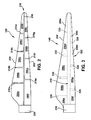
- an exemplary embodiment of a modularly constructed blade 140 is illustrated and includes a leading edge 202, a trailing edge 204, and a plurality of blade panels 206a-i in bonded association.
- At least one bonding line is representative of a seam or region at which the plurality of blade panels are bonded (i.e. where the bonded associations take place), wherein any adhesive bonding substance necessary to the desired end purpose may be used.
- Each of the at least one bonding lines can be disposed away from continuous contact with the leading edge 202 and/or the trailing edge 204 of the blade 24.
- a blade comprising at least three or more blade panels bonded via bonding lines disposed away from continuous contact with the leading edge 202 and/or the trailing edge 204 will offer additional improvement in the blade's constructability, containment and transportation.
- the plurality of blade panels are illustrated as panels 206a-i, and the at least one bonding line is illustrated as bonding lines 208 and intersecting bonding lines 210a-g.
- the blade 140 By constructing the blade 140 to include more than two blade panels (nine in the illustration), blade section length is decreased, allowing for easier and less costly transportation of each blade, as well as decreasing molding time per blade, improving molding tool turn-around time.
- Each panel has an overall length less than the length of a standard size shipping container. Shipping containers come in various standard sizes, with 20 foot, 40 foot and 45 foot containers being the most common, as well as, 48 foot and 53 foot containers.
- a 40 foot container is about forty feet long, eight feet wide and eight feet six inches high.
- Standard size shipping containers have greatly improved the logistics and cost of transportation.
- Most transportation equipment e.g., ships, maritime loading/unloading cranes, trucks, railway transport, etc.
- a system is provided to take advantage of the presently available standard size shipping containers for transportation of wind turbine components.
- Blade 140 can comprise a longitudinal spar beam 310, and a plurality of leading edge joint plates 320 and a plurality of trailing edge joint plates 330.
- Fig. 3 illustrates a specific number of spar beams and joint plates, however, any number of spar beams or joint plates can be used as desired.
- the spar beams and joint plates may be of one-piece or multi-piece construction.
- leading edge joint plates 320 support the joint between adjacent leading edge panels (e.g., between panel 206f and panel 206g).
- trailing edge joint plates 330 support the joint between adjacent trailing edge panels (e.g., between panel 206a and panel 206b).
- the leading and trailing edge panels may be constructed of graphite composites, aluminum, metal alloys or wood laminates.
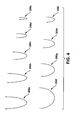
- each panel 206a-i of blade 140 can have a different cross sectional profile, and the profile can be tapered along the length of each individual section.
- the profiles are illustrated as shown in Fig. 4 . It can be seen that the first panel 206f of the leading edge has a wider profile than the subsequent panel 206g. As shown in this embodiment, each subsequent panel, progressing from the root section 220 to the tip section 230, has a progressively narrower profile. For example, of the leading edge panels, panel 206f is the widest, followed by panel 206g, then panel 206h, and panel 206i is the narrowest. Similarly, of the trailing edge panels, panel 206a is the widest, followed by panel 206b, then panel 206c, followed by panel 206d, and panel 206e is the narrowest of the trailing edge panels.
- This progressively narrow profile design for the individual panel components allows all or a portion of the panels comprising each trailing edge and leading edge to be arranged in a nested configuration.
- all the leading edge panels 206f-i and/or all the trailing edge panels 206a-e could be stacked together in a nested configuration.
- Nested can be defined as a set of objects of graduated size that can be stacked together, each fitting within the immediately larger one.
- a set of graduated bowls can have all the smaller bowls stacked or nested within the largest bowl.
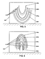
- Fig. 5 illustrates a standard size shipping container 520 that contains all the leading edge panels 206i-f therein. It may be advantageous to provide optional packing or cushioning material 510 between and around each individual panel.
- the packing material can protect the individual panels from damage during transport and loading or unloading.
- the packing material would provide a cushioning effect and could be comprised of natural fiber, rubber, latex, polyurethane, or memory foam materials. It can be seen that the panels are nested together and oriented in a U-shaped arrangement. However, the panels could also be placed in an inverted or upside down U-shaped arrangement as well. Orienting the panels sideways may not be the most preferred arrangement as stresses imposed during transport could damage the panels.
- blocking supports (not shown) may also be included within container 520 to further support the nested panels.
- a 40 foot shipping container could be used to transport all the panels of a leading or trailing edge. Assuming the blade is 50 meters long, a five panel leading edge section would easily fit within one 40 foot container. Multiple containers could be used to transport the entire blade or portions thereof.
- Fig. 6 illustrates one embodiment of transporting and containing all the panels of a trailing edge section.
- Standard size shipping container 520 contains all the trailing edge panels 206a-206e in a nested arrangement.
- Packing material 510 may be placed between and/or around individual panels.
- Fig. 6 shows an inverted U-shaped arrangement for transportation. It may be advantageous to have the panels stacked in a "U" shape ( Fig. 5 ) or an inverted "U" shape ( Fig. 6 ) to permit the first panel needed in the assembly process to be the first one available. For example, in Fig. 6 the first panel needed during the assembly process may be panel 206a followed by panel 206b. The arrangement shown in Fig. 6 would permit a more efficient assembly process by immediately exposing the first panel needed in the assembly process. As each panel is removed the next panel needed would be exposed and accessible.
- Fig. 7 illustrates a standard shipping container 520 that can be used to contain and transport the leading edge joint plates 320 and/or trailing edge joint plates 330.
- Packing material 710 may be placed below and/or around each joint plate to protect it during transport and the loading/unloading process.
- a standard size shipping container may be able to contain a nested stack of leading and/or trailing edge panels and some or all of the joint plates.
- leading edge panels could be arranged on one side of container 520 while the joint plates are arranged on the opposite side of the same container.
- the joint plates could be nested within the panels.
- One or more root components 220 could also be housed within a standard size shipping container, and the container housing the root may also have room for some or all of the joint plates.
- One or more spar beams 310 could also be housed within a standard size shipping container, and the container housing the spar beams may also have room for additional components such as, blade panels, joint plates and/or root components.
- the systems are cost-effective and efficient for supporting, containing and/or transporting wind turbine components. More specifically, in some embodiments, the systems support more than one blade or more than one component while being able to be contained within a standard size shipping container, and being sized, shaped, and/or weighted to comply with at least some restrictions on predetermined sized, shaped, and/or weight loads. As such, the systems may facilitate reducing a cost of transporting wind turbine components as compared with at least some known transportation containers and/or methods that only transport one entire component in its final completed form because they otherwise would not comply with at least some restrictions. Such size and/or shape that complies with at least some restrictions on predetermined sized and/or shaped loads may also facilitate transportation using more than one different mode of transportation.
- the systems described and/or illustrated herein may also facilitate reducing a cost of transporting wind turbine components by providing packing material or one or more cushions that are adjustable to accommodate a plurality of differently sized and/or shaped components, such that dedicated fixtures of different sizes and/or shapes may not be required for differently sized and/or shaped components.
- the packing or cushioning material may facilitate reducing or eliminating vibrational stresses and/or other forces induced into one or more components, for example during loading, unloading, and/or transportation.
- the systems described and/or illustrated herein may facilitate reducing or eliminating damage to wind turbine components, for example during loading, unloading, and/or transportation.
- the packing material, support fixtures or cushions may facilitate a secure coupling between one or more components and the container to facilitate retaining the component(s) within the container and in position during transportation and/or storage of the component(s).
Landscapes
- Engineering & Computer Science (AREA)
- Mechanical Engineering (AREA)
- Life Sciences & Earth Sciences (AREA)
- Sustainable Development (AREA)
- Sustainable Energy (AREA)
- Chemical & Material Sciences (AREA)
- Combustion & Propulsion (AREA)
- General Engineering & Computer Science (AREA)
- Wind Motors (AREA)
Claims (4)
- Système pour contenir ou transporter des pièces d'une éolienne (100), comportant :un conteneur (520) contenant une pluralité de pièces d'éolienne, ledit conteneur étant un conteneur d'expédition (520) de dimensions normales ; etdans lequel ladite pluralité de pièces d'éolienne comprend des parties d'une pale (140), caractérisé en ce que les parties de la pale (140) sont rangées dans une configuration à emboîtement dans ledit conteneur, de telle manière que les panneaux (206a-i) de la pale aient des dimensions graduelles permettant de les empiler les uns sur les autres, chacun se logeant dans toute partie ayant des dimensions immédiatement plus grandes, les panneaux (206a-i) de la pale étant orientés et emboîtés suivant une disposition en U ou en U inversé.
- Système selon la revendication 1, dans lequel une ou plusieurs plaques d'assemblage (320, 330) sont rangées à l'intérieur de l'unique conteneur d'expédition (520) de dimensions normales
- Système selon l'une quelconque des revendications précédentes, dans lequel une matière de rembourrage (510, 710) est placée entre lesdites pièces d'éolienne.
- Système selon la revendication 3, dans lequel ladite matière de rembourrage (510, 710) contient des fibres naturelles et/ou du caoutchouc et/ou du latex et /du polyuréthane et/ou de la mousse viscoélastique.
Applications Claiming Priority (1)
| Application Number | Priority Date | Filing Date | Title |
|---|---|---|---|
| US11/938,849 US8733549B2 (en) | 2007-11-13 | 2007-11-13 | System for containing and/or transporting wind turbine components |
Publications (3)
| Publication Number | Publication Date |
|---|---|
| EP2060504A1 EP2060504A1 (fr) | 2009-05-20 |
| EP2060504B1 EP2060504B1 (fr) | 2011-12-14 |
| EP2060504B2 true EP2060504B2 (fr) | 2015-10-14 |
Family
ID=40352223
Family Applications (1)
| Application Number | Title | Priority Date | Filing Date |
|---|---|---|---|
| EP08167783.3A Not-in-force EP2060504B2 (fr) | 2007-11-13 | 2008-10-29 | Système pour contenir et/ou transporter des composants d'éolienne |
Country Status (4)
| Country | Link |
|---|---|
| US (1) | US8733549B2 (fr) |
| EP (1) | EP2060504B2 (fr) |
| CN (1) | CN101434324B (fr) |
| ES (1) | ES2376283T5 (fr) |
Families Citing this family (11)
| Publication number | Priority date | Publication date | Assignee | Title |
|---|---|---|---|---|
| US20090206604A1 (en) * | 2008-02-15 | 2009-08-20 | Karl-Heinz Meiners | Method of transporting bulky equipment of a wind power plant, preassembled equipment |
| ATE511483T1 (de) * | 2008-07-04 | 2011-06-15 | Siemens Ag | Verfahren und vorrichtung zum ersetzen eines permanent-magnets |
| US7891939B1 (en) * | 2009-09-05 | 2011-02-22 | Zuteck Michael D | Hybrid multi-element tapered rotating tower |
| US8482247B2 (en) * | 2010-04-23 | 2013-07-09 | General Electric Company | Package foil for protecting wind turbine components from the environment, method for packaging a wind turbine component, and wind turbine component assembly |
| US9500179B2 (en) | 2010-05-24 | 2016-11-22 | Vestas Wind Systems A/S | Segmented wind turbine blades with truss connection regions, and associated systems and methods |
| US8562302B2 (en) * | 2010-07-06 | 2013-10-22 | General Electric Company | Wind turbine blade with integrated handling mechanism attachment bores |
| US8528735B2 (en) * | 2011-03-30 | 2013-09-10 | General Electric Company | Transport frame for nacelle/rotor hub unit of a wind turbine, method of transporting and mounting a nacelle/rotor hub unit |
| KR101571303B1 (ko) | 2014-05-30 | 2015-11-24 | 삼성중공업 주식회사 | 풍력 발전기의 컴포넌트 포장 용기 |
| US9394880B2 (en) | 2014-07-11 | 2016-07-19 | Michael Zuteck | Tall wind turbine tower erection with climbing crane |
| US20160039554A1 (en) * | 2014-08-08 | 2016-02-11 | Robert Bosch Llc | Brake Pad Kit Including an Absorbent Fabric Article |
| US11180363B2 (en) | 2020-02-07 | 2021-11-23 | Taiwan Semiconductor Manufacturing Company Limited | Outgassing material coated cavity for a micro-electro mechanical system device and methods for forming the same |
Citations (1)
| Publication number | Priority date | Publication date | Assignee | Title |
|---|---|---|---|---|
| US20070217918A1 (en) † | 2006-03-20 | 2007-09-20 | Baker Myles L | Lightweight composite truss wind turbine blade |
Family Cites Families (30)
| Publication number | Priority date | Publication date | Assignee | Title |
|---|---|---|---|---|
| US2142518A (en) * | 1938-05-13 | 1939-01-03 | Anchor Hocking Glass Corp | Packing means for hollow ware |
| US2365461A (en) * | 1944-09-27 | 1944-12-19 | Fairbanks Clarence La Verne | Punch press set |
| US2869649A (en) | 1953-04-07 | 1959-01-20 | Murdo Mackenzie | Helicopter rotor |
| CH539549A (de) * | 1971-12-31 | 1973-07-31 | Bbc Brown Boveri & Cie | Aufbewahrungs- und Transportbehälter für eine oder mehrere Schaufeln einer Strömungsmaschine |
| US3841053A (en) * | 1972-12-22 | 1974-10-15 | Weatherchem Corp | Method and apparatus for displaying product |
| US3896928A (en) * | 1973-08-24 | 1975-07-29 | Anchor Hocking Corp | Box for containing and displaying articles of merchandise |
| US4053049A (en) * | 1976-02-19 | 1977-10-11 | Federal-Mogul Corporation | Packaging of semicylindrical sleeve bearings |
| CH609232A5 (fr) * | 1977-01-26 | 1979-02-28 | Kuhn Heinrich Metall | |
| DE2921152C2 (de) | 1979-05-25 | 1982-04-22 | Messerschmitt-Bölkow-Blohm GmbH, 8000 München | Rotorblatt für Windkraftwerke |
| US4295790A (en) * | 1979-06-21 | 1981-10-20 | The Budd Company | Blade structure for use in a windmill |
| DE3113079C2 (de) | 1981-04-01 | 1985-11-21 | Messerschmitt-Bölkow-Blohm GmbH, 8000 München | Aerodynamischer Groß-Flügel und Verfahren zu dessen Herstellung |
| US4519746A (en) | 1981-07-24 | 1985-05-28 | United Technologies Corporation | Airfoil blade |
| JPH01153480A (ja) | 1987-12-10 | 1989-06-15 | Shigenobu Furukawa | 多目的コンテナ |
| US5628403A (en) * | 1996-01-16 | 1997-05-13 | Bill Thomas Associates, Inc. | Universal turbine blade packaging container |
| GB0109515D0 (en) * | 2001-04-17 | 2001-06-06 | Neg Micon As | A method for transporting a set of large longitudinal items, a package system to be used by the method and use of such a package system |
| US20030175089A1 (en) * | 2002-03-13 | 2003-09-18 | Preben Almind | Transport container for wind turbine blades |
| DE10214161C1 (de) * | 2002-03-28 | 2003-05-28 | Willibald Hergeth | Behältnis und Palette zur Aufnahme von Schaufeln einer Strömungsmaschine |
| DK175718B1 (da) | 2002-04-15 | 2005-02-07 | Ssp Technology As | Möllevinge |
| US6896134B2 (en) * | 2002-05-24 | 2005-05-24 | Hewlett-Packard Development Company, L.P. | Armored peripheral case |
| DE10225025A1 (de) * | 2002-06-06 | 2003-12-24 | Aloys Wobben | Vorrichtung zum Handhaben von Rotorblättern |
| JP4580169B2 (ja) | 2004-02-05 | 2010-11-10 | 富士重工業株式会社 | 風車用分割型ブレード及び風車の耐雷装置 |
| ES2253122B1 (es) * | 2004-11-11 | 2007-08-01 | Gamesa Eolica, S.A. Sociedad Unipersonal | Contenedor para el transporte de palas. |
| BRPI0405546F1 (pt) * | 2004-12-10 | 2016-03-22 | Tecsis Tecnologia E Sist S Avançados Ltda | desenvolvimento em conjunto de estruturas para manuseio, transporte e armazenamento de pás para rotores de aerogeradores |
| US20060213145A1 (en) * | 2005-03-22 | 2006-09-28 | Haller Mark E | Lattice-skin hybrid tower |
| US20060225278A1 (en) | 2005-03-31 | 2006-10-12 | Lin Wendy W | Wind blade construction and system and method thereof |
| US7798780B2 (en) | 2005-12-19 | 2010-09-21 | General Electric Company | Modularly constructed rotorblade and method for construction |
| US7704024B2 (en) * | 2006-01-31 | 2010-04-27 | General Electric Company | Methods and systems for transporting wind turbine components |
| US20070177954A1 (en) | 2006-01-31 | 2007-08-02 | General Electric Company | Method and apparatus for containing and/or transporting rotor blades |
| US7654799B2 (en) | 2006-04-30 | 2010-02-02 | General Electric Company | Modular rotor blade for a wind turbine and method for assembling same |
| US7874053B2 (en) * | 2006-06-20 | 2011-01-25 | John Stangel | Door converter assembly for storage containers |
-
2007
- 2007-11-13 US US11/938,849 patent/US8733549B2/en not_active Expired - Fee Related
-
2008
- 2008-10-29 EP EP08167783.3A patent/EP2060504B2/fr not_active Not-in-force
- 2008-10-29 ES ES08167783.3T patent/ES2376283T5/es active Active
- 2008-11-13 CN CN2008101738883A patent/CN101434324B/zh not_active Expired - Fee Related
Patent Citations (1)
| Publication number | Priority date | Publication date | Assignee | Title |
|---|---|---|---|---|
| US20070217918A1 (en) † | 2006-03-20 | 2007-09-20 | Baker Myles L | Lightweight composite truss wind turbine blade |
Also Published As
| Publication number | Publication date |
|---|---|
| EP2060504B1 (fr) | 2011-12-14 |
| CN101434324A (zh) | 2009-05-20 |
| US20090120830A1 (en) | 2009-05-14 |
| ES2376283T3 (es) | 2012-03-12 |
| EP2060504A1 (fr) | 2009-05-20 |
| CN101434324B (zh) | 2013-10-23 |
| ES2376283T5 (es) | 2015-11-30 |
| US8733549B2 (en) | 2014-05-27 |
Similar Documents
| Publication | Publication Date | Title |
|---|---|---|
| EP2060504B2 (fr) | Système pour contenir et/ou transporter des composants d'éolienne | |
| EP1813473B1 (fr) | Procédé et appareil pour contenir et/ou transporter des pales de rotor | |
| US7832987B2 (en) | Methods of handling a wind turbine blade and system therefor | |
| EP1997681B1 (fr) | Procédé et appareil pour contenir, stocker et/ou transporter des pales inclinées de rotor d'éolienne | |
| US8622670B2 (en) | Three aerogenerator blades packing system (packing method and packing system for three aerogenerator blades) | |
| AU2010201940B2 (en) | Fixture for gripping an end of a member | |
| EP2077363A2 (fr) | Joints de tour d'éolienne | |
| EP2628945A2 (fr) | Dispositif d'expédition et procédé de transport de pales de rotor | |
| EP2133558B1 (fr) | Système et procédé de transport de sections de tour d'éolienne sur un navire de transport | |
| EP2085612A2 (fr) | Nacelle empilable pour éolienne | |
| US20240247637A1 (en) | A wind turbine with a nacelle having an offset center of gravity | |
| CN109642546B (zh) | 用于风力涡轮机叶片的运输和存储系统 | |
| US20120027611A1 (en) | Compression member for wind turbine rotor blades | |
| KR200497992Y1 (ko) | 풍력발전기 및 풍력발전기 일체형 컨테이너 장치 | |
| CN109072865B (zh) | 用于运输和/或存储风力涡轮机叶片壳体半部件的系统及相关方法 | |
| KR20250111987A (ko) | 풍력발전설비의 블레이드 구조체 |
Legal Events
| Date | Code | Title | Description |
|---|---|---|---|
| PUAI | Public reference made under article 153(3) epc to a published international application that has entered the european phase |
Free format text: ORIGINAL CODE: 0009012 |
|
| AK | Designated contracting states |
Kind code of ref document: A1 Designated state(s): AT BE BG CH CY CZ DE DK EE ES FI FR GB GR HR HU IE IS IT LI LT LU LV MC MT NL NO PL PT RO SE SI SK TR |
|
| AX | Request for extension of the european patent |
Extension state: AL BA MK RS |
|
| 17P | Request for examination filed |
Effective date: 20091120 |
|
| 17Q | First examination report despatched |
Effective date: 20091211 |
|
| AKX | Designation fees paid |
Designated state(s): DE ES IT |
|
| GRAP | Despatch of communication of intention to grant a patent |
Free format text: ORIGINAL CODE: EPIDOSNIGR1 |
|
| GRAS | Grant fee paid |
Free format text: ORIGINAL CODE: EPIDOSNIGR3 |
|
| GRAA | (expected) grant |
Free format text: ORIGINAL CODE: 0009210 |
|
| AK | Designated contracting states |
Kind code of ref document: B1 Designated state(s): DE ES IT |
|
| REG | Reference to a national code |
Ref country code: DE Ref legal event code: R096 Ref document number: 602008011949 Country of ref document: DE Effective date: 20120308 |
|
| REG | Reference to a national code |
Ref country code: ES Ref legal event code: FG2A Ref document number: 2376283 Country of ref document: ES Kind code of ref document: T3 Effective date: 20120312 |
|
| PLBI | Opposition filed |
Free format text: ORIGINAL CODE: 0009260 |
|
| 26 | Opposition filed |
Opponent name: BLADE DYNAMICS LIMITED Effective date: 20120912 |
|
| PLAX | Notice of opposition and request to file observation + time limit sent |
Free format text: ORIGINAL CODE: EPIDOSNOBS2 |
|
| REG | Reference to a national code |
Ref country code: DE Ref legal event code: R026 Ref document number: 602008011949 Country of ref document: DE Effective date: 20120912 |
|
| PLAF | Information modified related to communication of a notice of opposition and request to file observations + time limit |
Free format text: ORIGINAL CODE: EPIDOSCOBS2 |
|
| PLBB | Reply of patent proprietor to notice(s) of opposition received |
Free format text: ORIGINAL CODE: EPIDOSNOBS3 |
|
| PLAB | Opposition data, opponent's data or that of the opponent's representative modified |
Free format text: ORIGINAL CODE: 0009299OPPO |
|
| R26 | Opposition filed (corrected) |
Opponent name: BLADE DYNAMICS LIMITED Effective date: 20120912 |
|
| RIC2 | Information provided on ipc code assigned after grant |
Ipc: F03D 1/00 20060101ALI20141205BHEP Ipc: B65D 85/62 20060101ALI20141205BHEP Ipc: B65D 85/68 20060101ALI20141205BHEP Ipc: B65D 57/00 20060101AFI20141205BHEP |
|
| APBM | Appeal reference recorded |
Free format text: ORIGINAL CODE: EPIDOSNREFNO |
|
| APBP | Date of receipt of notice of appeal recorded |
Free format text: ORIGINAL CODE: EPIDOSNNOA2O |
|
| APAH | Appeal reference modified |
Free format text: ORIGINAL CODE: EPIDOSCREFNO |
|
| APBU | Appeal procedure closed |
Free format text: ORIGINAL CODE: EPIDOSNNOA9O |
|
| PUAH | Patent maintained in amended form |
Free format text: ORIGINAL CODE: 0009272 |
|
| STAA | Information on the status of an ep patent application or granted ep patent |
Free format text: STATUS: PATENT MAINTAINED AS AMENDED |
|
| 27A | Patent maintained in amended form |
Effective date: 20151014 |
|
| AK | Designated contracting states |
Kind code of ref document: B2 Designated state(s): DE ES IT |
|
| REG | Reference to a national code |
Ref country code: DE Ref legal event code: R102 Ref document number: 602008011949 Country of ref document: DE |
|
| REG | Reference to a national code |
Ref country code: ES Ref legal event code: DC2A Ref document number: 2376283 Country of ref document: ES Kind code of ref document: T5 Effective date: 20151130 |
|
| PGFP | Annual fee paid to national office [announced via postgrant information from national office to epo] |
Ref country code: IT Payment date: 20200917 Year of fee payment: 13 Ref country code: ES Payment date: 20201102 Year of fee payment: 13 Ref country code: DE Payment date: 20200917 Year of fee payment: 13 |
|
| REG | Reference to a national code |
Ref country code: DE Ref legal event code: R119 Ref document number: 602008011949 Country of ref document: DE |
|
| PG25 | Lapsed in a contracting state [announced via postgrant information from national office to epo] |
Ref country code: DE Free format text: LAPSE BECAUSE OF NON-PAYMENT OF DUE FEES Effective date: 20220503 |
|
| PG25 | Lapsed in a contracting state [announced via postgrant information from national office to epo] |
Ref country code: IT Free format text: LAPSE BECAUSE OF NON-PAYMENT OF DUE FEES Effective date: 20211029 |
|
| REG | Reference to a national code |
Ref country code: ES Ref legal event code: FD2A Effective date: 20230215 |
|
| PG25 | Lapsed in a contracting state [announced via postgrant information from national office to epo] |
Ref country code: ES Free format text: LAPSE BECAUSE OF NON-PAYMENT OF DUE FEES Effective date: 20211030 |