EP2060685A2 - Plaque de montage pour une cuvette de drainage - Google Patents
Plaque de montage pour une cuvette de drainage Download PDFInfo
- Publication number
- EP2060685A2 EP2060685A2 EP08169040A EP08169040A EP2060685A2 EP 2060685 A2 EP2060685 A2 EP 2060685A2 EP 08169040 A EP08169040 A EP 08169040A EP 08169040 A EP08169040 A EP 08169040A EP 2060685 A2 EP2060685 A2 EP 2060685A2
- Authority
- EP
- European Patent Office
- Prior art keywords
- mounting plate
- bowl
- drain
- sections
- recess
- Prior art date
- Legal status (The legal status is an assumption and is not a legal conclusion. Google has not performed a legal analysis and makes no representation as to the accuracy of the status listed.)
- Withdrawn
Links
Images



Classifications
-
- E—FIXED CONSTRUCTIONS
- E03—WATER SUPPLY; SEWERAGE
- E03F—SEWERS; CESSPOOLS
- E03F5/00—Sewerage structures
- E03F5/04—Gullies inlets, road sinks, floor drains with or without odour seals or sediment traps
- E03F5/0401—Gullies for use in roads or pavements
- E03F5/0405—Gullies for use in roads or pavements with an odour seal
- E03F5/0406—Gullies for use in roads or pavements with an odour seal the odour seal being easily accessible for cleaning
-
- E—FIXED CONSTRUCTIONS
- E03—WATER SUPPLY; SEWERAGE
- E03F—SEWERS; CESSPOOLS
- E03F5/00—Sewerage structures
- E03F5/04—Gullies inlets, road sinks, floor drains with or without odour seals or sediment traps
- E03F5/0407—Floor drains for indoor use
-
- E—FIXED CONSTRUCTIONS
- E03—WATER SUPPLY; SEWERAGE
- E03F—SEWERS; CESSPOOLS
- E03F5/00—Sewerage structures
- E03F5/04—Gullies inlets, road sinks, floor drains with or without odour seals or sediment traps
- E03F2005/0412—Gullies inlets, road sinks, floor drains with or without odour seals or sediment traps with means for adjusting their position with respect to the surrounding surface
- E03F2005/0413—Gullies inlets, road sinks, floor drains with or without odour seals or sediment traps with means for adjusting their position with respect to the surrounding surface for height adjustment
-
- E—FIXED CONSTRUCTIONS
- E03—WATER SUPPLY; SEWERAGE
- E03F—SEWERS; CESSPOOLS
- E03F5/00—Sewerage structures
- E03F5/04—Gullies inlets, road sinks, floor drains with or without odour seals or sediment traps
- E03F2005/0416—Gullies inlets, road sinks, floor drains with or without odour seals or sediment traps with an odour seal
- E03F2005/0418—Gullies inlets, road sinks, floor drains with or without odour seals or sediment traps with an odour seal in the form of a bell siphon
Definitions
- the present invention concerns a mounting plate adapted for use in a floor drain, including a round drain bowl with a rim which is received in a recess in the mounting plate.
- the mounting plate may have a four-edged cross-section which either may be a rectangular cross-section or a square cross-section, as it is easier hereby to perform the installation in the floor instead for installing round drain bowls. Moreover, the material in the corners will provide a stronger construction.
- the mounting plates are also used in order to perform height adjustment with regard to the floor covering and the height of drain bowls.
- a drawback of this construction is that the spacers form holes under the mounting plate into where filler material can penetrate if casting is to be performed on the surrounding floor. Moreover, it is only possible to set it at a few discrete levels, depending on the thickness of the spacers.
- a mounting plate of the type specified in the introduction which is peculiar in that the mounting plate is formed by two sections, each having a cutout including the recess at an opposing side edge for receiving the rim of the drain bowl and which is provided with connecting means for mutual fastening of the two sections around the drain bowl mounted therein.
- a combination of a mounting plate and a round drain bowl will be peculiar in that the drain bowl includes an outer bowl and an inner bowl which are mutually telescopingly interconnected.
- the mounting it is possible to turn the mounting plate such that it is oriented correctly according to the surrounding floor, irrespective of the orientation of the round drain bowl.
- cutouts in the two sections of the mounting plate together forming a recess in which the rim of the drain bowl is received, it will be possible to make a permanent and tight connection.
- the mounting plate around a drain bowl and then positioning it in a milled recess in a wooden floor.
- a completely plane floor surface which is ready for application of membrane and/or floor vinyl.
- the floor vinyl/the membrane may be drawn in over the mounting plate, and the drain bowl may in a known way be of a type which is intended for use together with the floor vinyl/membrane.
- a connection which is suited for use in establishing an epoxy floor, tile floor, concrete floor or other floor types.
- a top part may e.g. be ring which is intended for securing floor vinyl or it may be another top part required for floor covering that is desired in connection with the floor drain. It is noted that a milled recess in the wooden floor is optional, as the mounting plate may lie on top of the floor.
- the mounting plate according to the present invention is peculiar in that the recess is made as channel-shaped groove.
- a collar on the drain bowl may fit into the channel-shaped groove and be clamped or be loosely received therein.
- the drain bowl may thus be mounted and secured in a simple way in the mounting plate alone in that a collar on the rim of the drain bowl is received in the channel-shaped groove.
- the mounting plate according to the present invention is peculiar in that the two sections are identical. This provides a particularly simple design of the mounting plate. Moreover, this is suitable for fitters as they only need to have a single type of element for use in the mounting.
- the two sections are made of plastic and can thus be made in one and the same mould.
- the mounting plate according to the present invention is peculiar in that the connecting means include corresponding tongues and cutouts on the two sections.
- the connecting means include corresponding tongues and cutouts on the two sections.
- the mounting plate according to the present invention is peculiar in that the connecting means include snap locks.
- the two sections may thus be provided with tongues which are resilient and which may act as snap means.
- the mounting plate is hereby secured around the drain bowl before mounting in the floor. In the finished construction, for safety reasons there will most often be provided a screwing together of the elements in the mounting plate and/or the wooden floor where it is fitted.
- the mounting plate according to the present invention is peculiar in that the recess is designed for receiving the rim of the drain bowl in a loose fit that allows mutual rotation. As mentioned previously, hereby is enabled adjusting the orientation of the drain bowl after having positioned and embedded the mounting plate in a floor construction.
- the mounting plate is used in combination with a round drain bowl which has a bottom part and a top part in the shape of an outer and an inner bowl, which are mutually telescopingly interconnected, it will be possible to perform a stepless and very flexible height adjustment of the drain bowl by displacing the inner and the outer bowl. Hereby, the mounting is facilitated.
- the combination of mounting plate and drain bowl is peculiar in that there is provided a rim on the outer bowl for interacting with the recess for receiving the rim of the drain bowl.
- the rim on the drain bowl may interact with a recess that preferably can be channel-shaped.
- the outer bowl of the drain bowl will hereby be retained in the recess, after which the inner bowl may easily be displaced up and down in the outer bowl. It may be regarded as a telescoping connection between inner bowl and outer bowl with packings provided there between. By a proper choice of packing between the two bowls, there may furthermore be established a fine adjustment of the position of the inner bowl in relation to the retained outer bowl. This is important with regard to sealing between the edge of the inner bowl and floor covering.
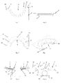
- Fig. 1 - 4 shows a section 1 for forming a four-edged mounting plate which in the shown embodiment is square. This is effected in that two sections 1, as shown in each of Figs. 5-14 , respectively, are assembled for forming the mounting plate.
- a section is provided a cutout 3 at a side edge 2, which together with a corresponding cutout forms a round opening for receiving a drain bowl 4.
- the cutout 3 will be disposed at opposing side edges.
- a recess 6 for receiving a rim 5 (see Fig. 8 ) of the drain bowl 4 is provided in the cutout 3.
- the drain bowl 4 is shown as a unit. In practice, the drain bowl 4 is formed by an outer bowl and an inner bowl which are mutually displaceable, such as explained later and as shown in Figs. 13 and 14 .
- the recess 6 is formed as a channel-shaped groove.
- Each of the sections 1 include connecting means in the form of a tongue 7 and cutout 8.
- the tongue 7 will interact with a corresponding cutout when the two elements are interconnected.
- a screw hole 9, 10 for fastening a screw 11, 12 (see Fig. 10 ) for additional safeguarding of the mutual retention of the two section around the drain bowl 4.
- Each section is furthermore provided with a snap-acting projection 13 which interacts with a corresponding notch 14.
- each section is provided with a number of countersunk screw holes 15 that may be used by mounting a top part, as e.g. a ring above the drain bowl 4.
- a top part as e.g. a ring above the drain bowl 4.
- the countersunk screw holes 15 are formed in these recesses, the downwards directed offsets around screw holes in such a top part/ring are accommodated such that the top part/ring can be brought into tight contact against the mounting plate.
- each mounting plate is provided with a number of screw holes 16 for use in mounting screws 17 for fastening the mounting plate to an underlying wooden floor 18 (see e.g. Fig. 9 ).
- the shown section 1 is made from plastic, preferably by injection moulding. Alternatively, the section 1 can be made from other materials and/or by other manufacturing methods.
- Figs. 5-8 is seen a situation where two sections 1 are about to be assembled around a round drain bowl 4.
- the drain bowl has a lateral outlet 30.
- the drain bowl 4 is provided with a rim 5 which is received in the recess 6.
- a packing 19 and a ring 31 are provided at the rim 5 which ensure tightness between the mounting plate and the outer bowl 23 of the drain bowl 4.
- each section 1 is provided at the underside with a number of ribs 20 which reinforce the mounting plate, as they are provided in contact with the underside of the flange 26 of the mounting plate and with side edges on a bushing-like projections 21 in which the recess 6 is formed.
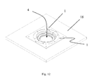
- Figs. 9-12 show how the four-edged mounting plate is formed by the two sections 1 which are connected to each other with the drain bowl 4 secured there between, as the drain bowl extends through an opening 25 formed in the wooden floor 18.
- the flange 26 of the mounting plate will extend around the opening 25 wherein the drain is fitted.
- the flange 26 is provided with a recess 27 towards the surface of the wooden floor 18.
- it will only be the outermost rim area 28 of the flange which is in contact with the wooden floor 18.
- a possible casting layer which is poured on the wooden floor 18 up to the side edge 29 of the mounting plate will thus not be able to penetrate in under the mounting plate.
- Figs. 13 and 14 the combination of the mounting plate and the drain bowl is shown in sectional views for illustrating the inner bowl 24 and outer bowl 23 of the drain bowl 4.
- the drain bowl 4 is formed by the outer bowl 23 and the inner bowl 24.
- the inner bowl 24 is disposed inside the outer bowl 23 in a telescoping way with a slide packing 32 there between.
- the rim 5 will thus be provided on the outer bowl 23. In this way, the inner bowl 24 may be displaced in relation to the mounting plate and the outer bowl 23 retained therein when the two sections 1 are interconnected.
- the inner bowl 24 is seen in a position where it is inserted in the outer bowl 23.
- the inner bowl 24 is seen in a position where it is displaced out from the outer bowl 23. This telescoping displacement enables using one and the same floor drain for different types of floor covering and for casting layers with different thicknesses and slope towards the floor drain.
Landscapes
- Health & Medical Sciences (AREA)
- Life Sciences & Earth Sciences (AREA)
- Engineering & Computer Science (AREA)
- Hydrology & Water Resources (AREA)
- Public Health (AREA)
- Water Supply & Treatment (AREA)
- Floor Finish (AREA)
- Sink And Installation For Waste Water (AREA)
Applications Claiming Priority (1)
| Application Number | Priority Date | Filing Date | Title |
|---|---|---|---|
| DK200701615A DK176745B1 (da) | 2007-11-13 | 2007-11-13 | Monteringsplade samt kombination af monteringsplade og aflöbsskål |
Publications (2)
| Publication Number | Publication Date |
|---|---|
| EP2060685A2 true EP2060685A2 (fr) | 2009-05-20 |
| EP2060685A3 EP2060685A3 (fr) | 2013-09-04 |
Family
ID=40300762
Family Applications (1)
| Application Number | Title | Priority Date | Filing Date |
|---|---|---|---|
| EP20080169040 Withdrawn EP2060685A3 (fr) | 2007-11-13 | 2008-11-13 | Plaque de montage pour une cuvette de drainage |
Country Status (2)
| Country | Link |
|---|---|
| EP (1) | EP2060685A3 (fr) |
| DK (1) | DK176745B1 (fr) |
Cited By (3)
| Publication number | Priority date | Publication date | Assignee | Title |
|---|---|---|---|---|
| US9297157B2 (en) | 2012-02-27 | 2016-03-29 | Matthew Brian Wendorff | Toilet closet flange support kit |
| EP3031990B1 (fr) * | 2014-12-11 | 2020-03-18 | HL Hutterer & Lechner GmbH | Siphon de sol |
| EP4711541A3 (fr) * | 2024-09-12 | 2026-04-01 | Vieser Oy | Agencement pour un drain de sol |
Families Citing this family (1)
| Publication number | Priority date | Publication date | Assignee | Title |
|---|---|---|---|---|
| CN101649647B (zh) * | 2009-07-08 | 2011-10-26 | 深圳市天坤科技有限公司 | 一种地漏和地漏橡胶逆止阀 |
Family Cites Families (3)
| Publication number | Priority date | Publication date | Assignee | Title |
|---|---|---|---|---|
| US1613926A (en) * | 1925-08-07 | 1927-01-11 | Bropson James | Closet connection |
| US6435563B2 (en) * | 1998-01-08 | 2002-08-20 | Gpj Limited | Mounting ring for water closet coupling and method of installation |
| DK176110B1 (da) * | 2005-02-02 | 2006-07-31 | Bluecher Metal As | Gulvaflöb |
-
2007
- 2007-11-13 DK DK200701615A patent/DK176745B1/da not_active IP Right Cessation
-
2008
- 2008-11-13 EP EP20080169040 patent/EP2060685A3/fr not_active Withdrawn
Cited By (3)
| Publication number | Priority date | Publication date | Assignee | Title |
|---|---|---|---|---|
| US9297157B2 (en) | 2012-02-27 | 2016-03-29 | Matthew Brian Wendorff | Toilet closet flange support kit |
| EP3031990B1 (fr) * | 2014-12-11 | 2020-03-18 | HL Hutterer & Lechner GmbH | Siphon de sol |
| EP4711541A3 (fr) * | 2024-09-12 | 2026-04-01 | Vieser Oy | Agencement pour un drain de sol |
Also Published As
| Publication number | Publication date |
|---|---|
| EP2060685A3 (fr) | 2013-09-04 |
| DK176745B1 (da) | 2009-06-02 |
Similar Documents
| Publication | Publication Date | Title |
|---|---|---|
| US9297157B2 (en) | Toilet closet flange support kit | |
| US8096002B2 (en) | Height adjustable shower waste | |
| US20200173160A1 (en) | Drain System for Use with a Tile Floor | |
| US8921712B1 (en) | Electrical box assembly for poured concrete floors | |
| US11505930B2 (en) | Floor drain system | |
| US6902491B2 (en) | Floating golf ball cup insert | |
| US20190106874A1 (en) | Semi-round drain body and linear drain system including the same | |
| PT1782721E (pt) | Elemento base de chuveiro com uma caleira de escoamento | |
| US20070044396A1 (en) | Variable space water guard system | |
| DK176745B1 (da) | Monteringsplade samt kombination af monteringsplade og aflöbsskål | |
| US7770333B2 (en) | Adapter ring for on-site waste treatment or drainage systems | |
| US9090030B2 (en) | Procedure for manufacturing pieces for the formation of a removable floor covering | |
| KR200488384Y1 (ko) | 배수 트랩 | |
| EP3601675B1 (fr) | Drain à fente pour dalles de béton et procédé de formation de pavage en béton | |
| US8966675B1 (en) | Water closet lifting device | |
| EP2390431B1 (fr) | Canal d'écoulement | |
| EP1688549A2 (fr) | Bouche d'égout | |
| US20050150040A1 (en) | Drain apparatus | |
| JP2010159586A (ja) | 土間廻り部の構造及びその施工方法 | |
| US20100247236A1 (en) | Asymmetric Slot Drain | |
| KR101426497B1 (ko) | 콘크리트 내설용 복합 인서트장치 | |
| EP1483462B1 (fr) | Ancre | |
| GB2483660A (en) | Shower floor installation | |
| US20050044805A1 (en) | Anchor | |
| EP1682734A1 (fr) | Dispositif d'amortissement |
Legal Events
| Date | Code | Title | Description |
|---|---|---|---|
| PUAI | Public reference made under article 153(3) epc to a published international application that has entered the european phase |
Free format text: ORIGINAL CODE: 0009012 |
|
| AK | Designated contracting states |
Kind code of ref document: A2 Designated state(s): AT BE BG CH CY CZ DE DK EE ES FI FR GB GR HR HU IE IS IT LI LT LU LV MC MT NL NO PL PT RO SE SI SK TR |
|
| AX | Request for extension of the european patent |
Extension state: AL BA MK RS |
|
| TPAC | Observations filed by third parties |
Free format text: ORIGINAL CODE: EPIDOSNTIPA |
|
| PUAL | Search report despatched |
Free format text: ORIGINAL CODE: 0009013 |
|
| REG | Reference to a national code |
Ref country code: SE Ref legal event code: TRCL |
|
| AK | Designated contracting states |
Kind code of ref document: A3 Designated state(s): AT BE BG CH CY CZ DE DK EE ES FI FR GB GR HR HU IE IS IT LI LT LU LV MC MT NL NO PL PT RO SE SI SK TR |
|
| AX | Request for extension of the european patent |
Extension state: AL BA MK RS |
|
| RIC1 | Information provided on ipc code assigned before grant |
Ipc: E03F 5/04 20060101AFI20130726BHEP |
|
| 17P | Request for examination filed |
Effective date: 20140211 |
|
| RBV | Designated contracting states (corrected) |
Designated state(s): AT BE BG CH CY CZ DE DK EE ES FI FR GB GR HR HU IE IS IT LI LT LU LV MC MT NL NO PL PT RO SE SI SK TR |
|
| AKX | Designation fees paid |
Designated state(s): AT BE BG CH CY CZ DE DK EE ES FI FR GB GR HR HU IE IS IT LI LT LU LV MC MT NL NO PL PT RO SE SI SK TR |
|
| 17Q | First examination report despatched |
Effective date: 20140523 |
|
| STAA | Information on the status of an ep patent application or granted ep patent |
Free format text: STATUS: THE APPLICATION IS DEEMED TO BE WITHDRAWN |
|
| 18D | Application deemed to be withdrawn |
Effective date: 20160308 |