EP2060687B1 - Vorrichtung zur Sicherstellung der Isolierung bei thermischer Trennung - Google Patents
Vorrichtung zur Sicherstellung der Isolierung bei thermischer Trennung Download PDFInfo
- Publication number
- EP2060687B1 EP2060687B1 EP07120936.5A EP07120936A EP2060687B1 EP 2060687 B1 EP2060687 B1 EP 2060687B1 EP 07120936 A EP07120936 A EP 07120936A EP 2060687 B1 EP2060687 B1 EP 2060687B1
- Authority
- EP
- European Patent Office
- Prior art keywords
- box
- cage
- bars
- sleeve
- designed
- Prior art date
- Legal status (The legal status is an assumption and is not a legal conclusion. Google has not performed a legal analysis and makes no representation as to the accuracy of the status listed.)
- Active
Links
Images


Classifications
-
- E—FIXED CONSTRUCTIONS
- E04—BUILDING
- E04B—GENERAL BUILDING CONSTRUCTIONS; WALLS, e.g. PARTITIONS; ROOFS; FLOORS; CEILINGS; INSULATION OR OTHER PROTECTION OF BUILDINGS
- E04B1/00—Constructions in general; Structures which are not restricted either to walls, e.g. partitions, or floors or ceilings or roofs
- E04B1/003—Balconies; Decks
- E04B1/0038—Anchoring devices specially adapted therefor with means for preventing cold bridging
Definitions
- the present invention relates to the field of construction, in particular to the realization of devices for insulating in the event of thermal breakage mainly in case of interruption in the insulation of buildings in general.
- the problems related to thermal bridges caused mainly by the interruption of the insulation at the junctions of external structure are well known in the field of construction.
- the devices intended to reduce these heat losses generally consist in ensuring the continuity of the thermal insulation by interposition of an insulation traversed only by point elements of metal structure which ensure the transmission of the forces (shearing force and bending moment).
- the device consists of a rigid or quasi-rigid insulating plate traversed by reinforcing bars also called concrete bars, preferably protected against corrosion, at least in line with the passage in the insulating element.
- the bars are anchored in the structural elements on either side of the insulating element. The device is placed so that the insulating element is in the extension of the current insulation of the building, whether external or internal to the supporting structure.
- this relatively rigid plate is made of a material that has characteristics that not only provide the required thermal, fireproof and acoustic insulation performance and correspond to the specifications but also serves as support for the reinforcing bars.
- the bars are arranged and sized to take up the bending moment by a traction-compression torque in the upper and lower horizontal bars that equip the device.
- a difficulty is to maintain the right distance between these bars not to change the forces in the bars by changing the lever arm.
- Spreading the bars leads to reduce the coating, bringing them together increases the efforts in the bars.
- this insulating material is not sufficiently resistant, the positioning of the bars requires to add mounting bars or other complicated devices that can also hinder the implementation when the elements are intended to integrate into a denser reinforcement (beams for example).
- this insulating material is relatively fragile, it can crumble especially around its periphery as the edges, for example, which will occur more often than the device is actually prefabricated in the workshop and must be transported on site or he may suffer damage.
- a possible solution is to provide stainless steel only for a reduced length on each side of the insulation and to weld a complement of traditional carbon steel bar.
- This advantageous device in terms of the cost of production is however related to the quality of the weld, precisely in the zone where the force is maximum and presents a risk of corrosion related to the formation of oxides during welding.
- the consequences of a faulty weld or corrosion can be dramatic in the case of hanging a balcony, since breaking a bar will cause an overload of the next bar that may not resist.
- the document DE19722028 discloses a construction element comprising an insulating material to be arranged in a substantially longitudinal direction between two building parts, and reinforcing bars which pass through the insulating material, the device comprising a profile in the form of an open cage and which defines an interior space in which the insulating material is disposed. Said construction element is adjustable in height to accommodate different floor thicknesses.
- the present invention is advantageously aimed at finding a solution to the problem of the state of the art and in particular to overcome the various disadvantages described above.
- the present invention aims to provide a solution that does not use the strength of the insulating plate as a support for the proper placement of rebar.
- the present invention aims to provide a solution that allows to choose the appropriate insulation only according to its thermal, fire and / or acoustic characteristics without having to check the stability characteristics of said plate.
- the present invention aims to provide a solution for a device that provides insulation during easy transport and for the protection of the insulating material.
- Another object of the present invention is to provide an element which limits the length of the reinforcing bars preferably made of stainless steel in order to maintain the advantage of the reduced cost, by mechanically joining the current bars to eliminate the risk associated with welding while reducing the number of parts to be assembled and therefore the cost of assembly.
- An essential characteristic of the invention lies in the actual design of the product in that it produces a non-deformable box or cage which serves as a support for the reinforcing bars necessary for stability and which can be filled with an insulation of any type to meet thermal, acoustic and / or fire resistance requirements.
- the present invention relates to a device for providing thermal break insulation in the form of a building element, comprising an insulating material to be disposed in a substantially longitudinal direction between two building parts, and reinforcing bars (4,6) which pass through the insulating material, the device comprising a profile in the form of a box or cage (1,3) open or closed and which defines an interior space (7). ) in which is disposed said insulating material.
- Said box or said cage has at least in a cross section a substantially rectangular rectangular periphery completely closed and has the essential shape of a rectangular parallelepiped.
- the profile intended to make said box or said cage has characteristics of rigidity or crush resistance.
- the profile is made of a metallic or polymeric material.
- said cage or said box comprises at least two distant surfaces arranged longitudinally opposite and intended to maintain at least the upper face and the lower face of the box or cage.
- the two opposite upper and lower surfaces are connected by spacers or walls.
- the upper and lower surfaces are solid or perforated.
- the side walls of the box are solid or perforated.
- the thickness of the cage or the box is calculated according to the choice of insulating material filling the space constituted by said cage or said box.
- the side walls of the box have orifices allowing the passage of reinforcing bars or their accessories.
- straight bars or slashes pass through said box.
- the device comprises at least one obliquely diagonally arranged slash and the dimensions of said box or of said cage are calculated so that the elbows or radii of curvature of the obliquely diagonally arranged slash are found outside the internal space. .
- the device comprises a sleeve or an intermediate part making it possible to assemble two parts of current reinforcing bars, said sleeve or said intermediate part being placed directly within said box or said cage.
- said sleeve has in its central part a section reduction.
- the sleeve is provided with an external relief.
- the sleeve has at its ends inner ropes so as to receive the threaded ends of the reinforcing bars.
- the sleeves are sleeves for producing straight or oblique bars.
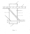
- the figure 1 describes the general principle underlying the invention.
- the figure 1 schematically describes in a sectional view a device which implements the principle according to a first aspect of the present invention.
- An essential feature of the invention is the presence of a rigid box or rigid cage equipped with reinforcing bars or other parts to ensure the stability of the structures, said box or said cage being filled with an insulating material that can be of any kind. nature according to the requirements of each particular application.
- Reinforcing bar means reinforcement bars intended to be poured into the concrete adjacent to the insulating element.
- these bars are also called concrete bars. They are usually made of steel, if possible stainless steel, but it is of course possible to consider using new particularly resistant materials, such as fiber elements or resin.
- Box or cage means a rigid non-deformable element which defines the space in which the insulating material is enclosed. This also means that in at least one cross section, the profile of the box or cage may have a completely closed periphery.
- the box or the cage has in at least the 4 directions perpendicular to the longitudinal direction of the completely closed walls, with the exception of openings intended for the passage of reinforcing bars or their accessories.
- the box or cage if it is further closed on its last two faces, that is to say on the six faces so as to make a closed space in the form of a parallelepiped, one could even consider the use of insulating material in granular form, fibrous or even in the form of gel or foam that could be injected or even poured into the closed space.
- the box or cage may be partially open or have partially perforated walls.
- the box or cage comprises two continuous profiles, the first upper (1) and the second lower (2) held at a distance by spacers (3) preferably punctual to form a box or cage relatively rigid or dimensionally stable to which are fixed bars upper armature (4), lower (5) and diagonally (6).
- the free space (7) inside the box or cage is filled with a suitable insulating material, even without great rigidity, which best meets the requirements of each particular situation.
- the upper part of the box or cage is composed of three distinct profiles, two lateral profiles and surmounted by a lid.
- the lower part is composed of two lateral profiles and a lid.
- the lateral parts are held at a distance by spacers to stiffen the box or cage.
- Upper, lower and diagonal bars are attached to the side profiles and are therefore in no way supported by the insulation that fills the cavity inside the box or cage.
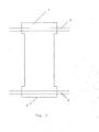
- the upper and lower parts may not be continuous and leave openings, as well as the lateral spacers could be continuous to form solid walls on each side of the insulation. All combinations are possible and the examples given to figures 2 and 3 are not limitations of the invention. At the extreme, the box could be completely closed on its periphery or widely open on all sides. Finally, the bars represented are not a limitation, they are elements of stability and their presence or shape depends on the efforts to be transmitted. Similarly the constituent material is not a limitation, the term "steel reinforcing bar" is used for a preferred form of the invention, but any other material for transmitting the forces can be envisaged.
- the “sleeve” is advantageously as an intermediate piece or interlayer between 2 reinforcing bars.
- the sleeve may have a certain relief to prevent the possible progression of the water towards the bars attaching to the ends.
- the figure 4 shows a preferred example of a long sleeve (10).
- the ends (20) are worked to mechanically fasten common concrete bars (30).
- the central zone (40) may advantageously have a section reduction to reduce heat flow and a certain relief (50) may be marked to stop a possible flow of water.
- the figure 5 shows explicitly an embodiment using a sleeve.
- An insulating plate (60) preferably rigid or semi-rigid, possibly enclosed in an indeformable cage, is traversed by a long sleeve (10).
- This sleeve is preferably made of steel and is protected against corrosion. It has a section reduction (40) in the passage of the insulating material (60) to reduce heat losses. Bars (30) are mechanically attached to the ends of the sleeve.
- the sleeve may further be advantageously provided with relief (50) intended to prevent the possible progression of the water towards the bars (30) which are not protected against corrosion.
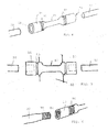
- the figure 6 shows an example of sleeve (10).
- the mechanical joint is made by a thread (70) on the bars (30) which will overlap with the bars of the adjacent structures and by an internal thread (80) in the sleeve (10) compatible with those made on the bars.
- the outer relief (50) is also shown in a preferred form, but could have any other form according to the invention.
- the figure 7 shows two embodiments of the invention when the bars are not in the same alignment, for example oblique or diagonal.
- the Sleeves (9a) and (9b) may have any profile, for example a bend or bend (100) for connecting the two bars (11) and (12) at an angle.
- the characteristic elements according to another embodiment of the invention are the following: it is a device for mechanically joining two common bars with a sleeve protected against corrosion.
- the sleeve is advantageously provided with a section reduction in its central part and preferably provided with a certain external relief.
- the sleeve is provided with internal threads at its ends.
- An important advantage of the present invention is to provide a fully equipped metal preferring profile that can be transported to the job site.
- a box or preferably metal cage and various sleeves directly attached to said cage or box its transport will be greatly facilitated. The assembly is then performed on site and aimed at fixing the reinforcing bars on the sleeves and to introduce if it has not already been made the insulating material within the cage or box.
- the material will be chosen insulation so as to ensure that the thickness of the box or cage is not too high and allows the radii of curvature of elbows slant or diagonally arranged along said box or cage are located outside thereof.
Landscapes
- Engineering & Computer Science (AREA)
- Architecture (AREA)
- Physics & Mathematics (AREA)
- Electromagnetism (AREA)
- Civil Engineering (AREA)
- Structural Engineering (AREA)
- Reinforcement Elements For Buildings (AREA)
Claims (16)
- Vorrichtung, die zur Sicherung der Isolation im Fall einer thermischen Trennung bestimmt ist, in Form eines Bauelements, umfassend ein Isolationsmaterial, das gemäß einer im wesentlichen Längsrichtung zwischen zwei Gebäudeteilen anzuordnen ist, und Armierungsstangen (4, 6), die das Isolationsmaterial durchqueren, wobei die Vorrichtung ein Profil in Form eines offenen oder geschlossenen Kastens oder Käfigs (1, 3) umfasst, der einen Innenraum (7) definiert, in dem das Isolationsmaterial angeordnet ist, dadurch gekennzeichnet, dass der Kasten oder der Käfig mindestens in einem transversalen Schnitt einen im wesentlichen rechteckigen, vollkommen geschlossenen Umfang aufweist und im wesentlichen die Form eines rechteckigen Parallelepipeders hat.
- Vorrichtung nach Anspruch 1, dadurch gekennzeichnet, dass das Profil, das zur Herstellung des Kastens oder des Käfigs bestimmt ist, Steifigkeits- oder Stauchfestigkeitseigenschaften aufweist.
- Vorrichtung nach Anspruch 2, dadurch gekennzeichnet, dass das Profil aus einem Metall- oder Polymermaterial hergestellt ist.
- Vorrichtung nach einem der vorangehenden Ansprüche, dadurch gekennzeichnet, dass der Käfig oder der Kasten mindestens zwei entfernte Flächen umfasst, die längs gegenüberliegend angeordnet sind und bestimmt, mindestens die Oberseite und die Unterseite des Kastens oder Käfigs zu halten.
- Vorrichtung nach Anspruch 4, dadurch gekennzeichnet, dass die zwei gegenüberliegenden oberen und unteren Flächen durch Abstandselemente oder Wände verbunden sind.
- Vorrichtung nach einem der Ansprüche 4 oder 5, dadurch gekennzeichnet, dass die oberen und unteren Flächen voll oder durchbrochen sind.
- Vorrichtung nach einem der vorangehenden Ansprüche, dadurch gekennzeichnet, dass die Seitenwände des Kastens voll oder durchbrochen sind.
- Vorrichtung nach einem der vorangehenden Ansprüche, dadurch gekennzeichnet, dass die Dicke des Käfigs oder des Kastens in Abhängigkeit von der Wahl des Isolationsmaterials berechnet ist, das den von dem Käfig oder dem Kasten gebildeten Raum füllt.
- Vorrichtung nach einem der vorangehenden Ansprüche, dadurch gekennzeichnet, dass die Seitenwände des Kastens Öffnungen aufweisen, die den Durchgang der Armierungsstangen oder ihres Zubehörs erlauben.
- Vorrichtung nach einem der vorangehenden Ansprüche, dadurch gekennzeichnet, dass gerade Stangen oder schräge Stangen den Kasten durchqueren.
- Vorrichtung nach einem der vorangehenden Ansprüche, die mindestens eine schräge Stange umfasst, die diagonal angeordnet ist, dadurch gekennzeichnet, dass die Abmessungen des Kastens oder des Käfigs derart berechnet sind, dass sich die Bögen oder Krümmungsradien der schrägen, diagonal angeordneten Stange außerhalb des Innenraums befinden.
- Vorrichtung nach einem der vorangehenden Ansprüche, dadurch gekennzeichnet, dass sie eine Muffe oder ein Zwischenstück umfasst, das erlaubt, zwei Stangenteile der laufenden Armierung zu verbinden, wobei die Muffe oder das Zwischenstück direkt im Kasten oder Käfig platziert ist.
- Vorrichtung nach Anspruch 12, dadurch gekennzeichnet, dass die Muffe in ihrem zentralen Teil eine Querschnittsreduzierung aufweist.
- Vorrichtung nach einem der Ansprüche 12 oder 13, dadurch gekennzeichnet, dass die Muffe mit einem Außenrelief ausgestattet ist.
- Vorrichtung nach einem der Ansprüche 12 bis 14, dadurch gekennzeichnet, dass die Muffe an ihren Enden innere Seile aufweist, um die gewindeten Enden der Armierungsstangen aufnehmen zu können.
- Vorrichtung nach einem der Ansprüche 12 bis 15, dadurch gekennzeichnet, dass die Muffen Muffen sind, die für die Herstellung von geraden oder schrägen Stangen bestimmt sind.
Priority Applications (1)
| Application Number | Priority Date | Filing Date | Title |
|---|---|---|---|
| EP07120936.5A EP2060687B1 (de) | 2007-11-16 | 2007-11-16 | Vorrichtung zur Sicherstellung der Isolierung bei thermischer Trennung |
Applications Claiming Priority (1)
| Application Number | Priority Date | Filing Date | Title |
|---|---|---|---|
| EP07120936.5A EP2060687B1 (de) | 2007-11-16 | 2007-11-16 | Vorrichtung zur Sicherstellung der Isolierung bei thermischer Trennung |
Publications (2)
| Publication Number | Publication Date |
|---|---|
| EP2060687A1 EP2060687A1 (de) | 2009-05-20 |
| EP2060687B1 true EP2060687B1 (de) | 2015-09-09 |
Family
ID=39402750
Family Applications (1)
| Application Number | Title | Priority Date | Filing Date |
|---|---|---|---|
| EP07120936.5A Active EP2060687B1 (de) | 2007-11-16 | 2007-11-16 | Vorrichtung zur Sicherstellung der Isolierung bei thermischer Trennung |
Country Status (1)
| Country | Link |
|---|---|
| EP (1) | EP2060687B1 (de) |
Families Citing this family (3)
| Publication number | Priority date | Publication date | Assignee | Title |
|---|---|---|---|---|
| PL3272957T3 (pl) * | 2016-07-22 | 2020-02-28 | Schöck Bauteile GmbH | Element konstrukcyjny do termoizolacji |
| BE1027282B1 (nl) | 2019-04-25 | 2020-12-15 | Schelde Handel Nv | Thermisch isolatiesamenstel, constructie en werkwijze voor het vormen van een thermische barrière en gebouw omvattend het samenstel |
| DE202022105156U1 (de) * | 2022-09-13 | 2022-10-06 | Leviat Ag | Verbindungsanordnung zur kraftübertragenden Anbindung eines ersten kraftaufnehmenden Bauwerkteils an ein zweites kraftaufnehmendes Bauwerkteil und Bauwerk |
Citations (1)
| Publication number | Priority date | Publication date | Assignee | Title |
|---|---|---|---|---|
| EP2000605A2 (de) * | 2007-06-08 | 2008-12-10 | Plakabeton S.A. | Vorrichtung und Zubehörteile zur Sicherstellung der Isolierung an thermischen Trennungen in Gebäudeisolierung |
Family Cites Families (2)
| Publication number | Priority date | Publication date | Assignee | Title |
|---|---|---|---|---|
| DE19722028B4 (de) | 1997-05-27 | 2005-09-01 | Schöck Bauteile GmbH | Bauelement zur Wärmedämmung |
| DE29805137U1 (de) * | 1998-03-23 | 1998-05-20 | Schöck Bauteile GmbH, 76534 Baden-Baden | Bauelement zur Wärmedämmung |
-
2007
- 2007-11-16 EP EP07120936.5A patent/EP2060687B1/de active Active
Patent Citations (1)
| Publication number | Priority date | Publication date | Assignee | Title |
|---|---|---|---|---|
| EP2000605A2 (de) * | 2007-06-08 | 2008-12-10 | Plakabeton S.A. | Vorrichtung und Zubehörteile zur Sicherstellung der Isolierung an thermischen Trennungen in Gebäudeisolierung |
Also Published As
| Publication number | Publication date |
|---|---|
| EP2060687A1 (de) | 2009-05-20 |
Similar Documents
| Publication | Publication Date | Title |
|---|---|---|
| EP1644592B1 (de) | Schalung mit erhöhtem widerstand für betonwand | |
| EP1207240A1 (de) | Schalung für eine Betonwand die auch als Bewehrung wirkt | |
| EP2000605A2 (de) | Vorrichtung und Zubehörteile zur Sicherstellung der Isolierung an thermischen Trennungen in Gebäudeisolierung | |
| EP2060687B1 (de) | Vorrichtung zur Sicherstellung der Isolierung bei thermischer Trennung | |
| EP4194631A1 (de) | Vorgefertigte verbundfassadenplatte und verfahren zur herstellung einer fassade eines gebäudes | |
| EP2479354B1 (de) | Modul das als thermische Trennung dient und mit einem Z-Profil ausgestattet ist | |
| EP2319998B1 (de) | Modul zur vermeidung thermischer brücken beinhaltend mindestens ein erdbebensicherungsprofil | |
| EP3061880B1 (de) | Fertigbalkon mit rippen | |
| EP2476822B1 (de) | Element zur thermischen Trennung zum Einbau in den Übergang zwischen einer Trennwand und einer Fassadenhülle einer Stahlbetonkonstruktion | |
| FR2939817A1 (fr) | Bloc elementaire prefabrique pour la construction d'un mur a isolation exterieure | |
| EP2907927A1 (de) | Vorrichtung zur Aussparung von Kanalisationsdurchlässen | |
| EP2899327B1 (de) | Dämmendes Bauelement und sein Herstellungsverfahren | |
| FR2954948A1 (fr) | Plancher collaborant a resistance mecanique renforcee | |
| EP1222340A1 (de) | Durchlässige schalungsplatte | |
| EP3763897B1 (de) | Hubanker für eine mauer mit integrierter schalung, und mauer mit integrierter schalung, die einen solchen hubanker umfasst | |
| FR2804703A1 (fr) | Procede de construction en beton arme a rupture thermique integree et construction ainsi obtenue | |
| FR2928390A1 (fr) | Element de construction en maconnerie de type poutre | |
| FR3057289B1 (fr) | Element de construction pour poutre mixe acier-beton arme, ensemble de construction et kits de construction | |
| FR2940337A1 (fr) | Poutrelle metallique pour la fabrication de planchers | |
| JP4759288B2 (ja) | 低層住宅用シングル配筋基礎の構築方法 | |
| EP4343079B1 (de) | Wandverbindungsbeschlag mit integrierter schalung | |
| EP2987921B1 (de) | Mauer mit thermisch getrennter integrierter schalung, bauverfahren eines gebäudes mit einer solchen mauer und so erhaltenes gebäude | |
| FR2757889A1 (fr) | Planchers realises a partir de dalles prefabriquees permettant de transmettre des efforts horizontaux sans dalle de compression rapportee sur chantier | |
| BE1017449A3 (fr) | Coffre pour volet roulant. | |
| FR2976301A1 (fr) | Structure de batiment. |
Legal Events
| Date | Code | Title | Description |
|---|---|---|---|
| PUAI | Public reference made under article 153(3) epc to a published international application that has entered the european phase |
Free format text: ORIGINAL CODE: 0009012 |
|
| AK | Designated contracting states |
Kind code of ref document: A1 Designated state(s): AT BE BG CH CY CZ DE DK EE ES FI FR GB GR HU IE IS IT LI LT LU LV MC MT NL PL PT RO SE SI SK TR |
|
| AX | Request for extension of the european patent |
Extension state: AL BA HR MK RS |
|
| 17P | Request for examination filed |
Effective date: 20091119 |
|
| 17Q | First examination report despatched |
Effective date: 20091222 |
|
| AKX | Designation fees paid |
Designated state(s): AT BE BG CH CY CZ DE DK EE ES FI FR GB GR HU IE IS IT LI LT LU LV MC MT NL PL PT RO SE SI SK TR |
|
| RBV | Designated contracting states (corrected) |
Designated state(s): AT BE BG CH CY CZ DE DK EE ES FI FR GB GR HU IE IS IT LI LT LU LV MC MT NL PL PT RO SE SI SK TR |
|
| GRAP | Despatch of communication of intention to grant a patent |
Free format text: ORIGINAL CODE: EPIDOSNIGR1 |
|
| INTG | Intention to grant announced |
Effective date: 20150318 |
|
| GRAS | Grant fee paid |
Free format text: ORIGINAL CODE: EPIDOSNIGR3 |
|
| GRAA | (expected) grant |
Free format text: ORIGINAL CODE: 0009210 |
|
| AK | Designated contracting states |
Kind code of ref document: B1 Designated state(s): AT BE BG CH CY CZ DE DK EE ES FI FR GB GR HU IE IS IT LI LT LU LV MC MT NL PL PT RO SE SI SK TR |
|
| REG | Reference to a national code |
Ref country code: GB Ref legal event code: FG4D Free format text: NOT ENGLISH |
|
| REG | Reference to a national code |
Ref country code: AT Ref legal event code: REF Ref document number: 748256 Country of ref document: AT Kind code of ref document: T Effective date: 20150915 Ref country code: CH Ref legal event code: EP |
|
| REG | Reference to a national code |
Ref country code: IE Ref legal event code: FG4D Free format text: LANGUAGE OF EP DOCUMENT: FRENCH |
|
| REG | Reference to a national code |
Ref country code: DE Ref legal event code: R096 Ref document number: 602007042989 Country of ref document: DE |
|
| REG | Reference to a national code |
Ref country code: FR Ref legal event code: PLFP Year of fee payment: 9 |
|
| REG | Reference to a national code |
Ref country code: NL Ref legal event code: MP Effective date: 20150909 |
|
| PG25 | Lapsed in a contracting state [announced via postgrant information from national office to epo] |
Ref country code: FI Free format text: LAPSE BECAUSE OF FAILURE TO SUBMIT A TRANSLATION OF THE DESCRIPTION OR TO PAY THE FEE WITHIN THE PRESCRIBED TIME-LIMIT Effective date: 20150909 Ref country code: LT Free format text: LAPSE BECAUSE OF FAILURE TO SUBMIT A TRANSLATION OF THE DESCRIPTION OR TO PAY THE FEE WITHIN THE PRESCRIBED TIME-LIMIT Effective date: 20150909 Ref country code: LV Free format text: LAPSE BECAUSE OF FAILURE TO SUBMIT A TRANSLATION OF THE DESCRIPTION OR TO PAY THE FEE WITHIN THE PRESCRIBED TIME-LIMIT Effective date: 20150909 Ref country code: GR Free format text: LAPSE BECAUSE OF FAILURE TO SUBMIT A TRANSLATION OF THE DESCRIPTION OR TO PAY THE FEE WITHIN THE PRESCRIBED TIME-LIMIT Effective date: 20151210 |
|
| REG | Reference to a national code |
Ref country code: LT Ref legal event code: MG4D |
|
| REG | Reference to a national code |
Ref country code: AT Ref legal event code: MK05 Ref document number: 748256 Country of ref document: AT Kind code of ref document: T Effective date: 20150909 |
|
| PG25 | Lapsed in a contracting state [announced via postgrant information from national office to epo] |
Ref country code: ES Free format text: LAPSE BECAUSE OF FAILURE TO SUBMIT A TRANSLATION OF THE DESCRIPTION OR TO PAY THE FEE WITHIN THE PRESCRIBED TIME-LIMIT Effective date: 20150909 Ref country code: SE Free format text: LAPSE BECAUSE OF FAILURE TO SUBMIT A TRANSLATION OF THE DESCRIPTION OR TO PAY THE FEE WITHIN THE PRESCRIBED TIME-LIMIT Effective date: 20150909 |
|
| PG25 | Lapsed in a contracting state [announced via postgrant information from national office to epo] |
Ref country code: NL Free format text: LAPSE BECAUSE OF FAILURE TO SUBMIT A TRANSLATION OF THE DESCRIPTION OR TO PAY THE FEE WITHIN THE PRESCRIBED TIME-LIMIT Effective date: 20150909 |
|
| PG25 | Lapsed in a contracting state [announced via postgrant information from national office to epo] |
Ref country code: IT Free format text: LAPSE BECAUSE OF FAILURE TO SUBMIT A TRANSLATION OF THE DESCRIPTION OR TO PAY THE FEE WITHIN THE PRESCRIBED TIME-LIMIT Effective date: 20150909 Ref country code: CZ Free format text: LAPSE BECAUSE OF FAILURE TO SUBMIT A TRANSLATION OF THE DESCRIPTION OR TO PAY THE FEE WITHIN THE PRESCRIBED TIME-LIMIT Effective date: 20150909 Ref country code: EE Free format text: LAPSE BECAUSE OF FAILURE TO SUBMIT A TRANSLATION OF THE DESCRIPTION OR TO PAY THE FEE WITHIN THE PRESCRIBED TIME-LIMIT Effective date: 20150909 Ref country code: IS Free format text: LAPSE BECAUSE OF FAILURE TO SUBMIT A TRANSLATION OF THE DESCRIPTION OR TO PAY THE FEE WITHIN THE PRESCRIBED TIME-LIMIT Effective date: 20160109 Ref country code: SK Free format text: LAPSE BECAUSE OF FAILURE TO SUBMIT A TRANSLATION OF THE DESCRIPTION OR TO PAY THE FEE WITHIN THE PRESCRIBED TIME-LIMIT Effective date: 20150909 |
|
| PG25 | Lapsed in a contracting state [announced via postgrant information from national office to epo] |
Ref country code: PT Free format text: LAPSE BECAUSE OF FAILURE TO SUBMIT A TRANSLATION OF THE DESCRIPTION OR TO PAY THE FEE WITHIN THE PRESCRIBED TIME-LIMIT Effective date: 20160111 Ref country code: RO Free format text: LAPSE BECAUSE OF FAILURE TO SUBMIT A TRANSLATION OF THE DESCRIPTION OR TO PAY THE FEE WITHIN THE PRESCRIBED TIME-LIMIT Effective date: 20150909 Ref country code: PL Free format text: LAPSE BECAUSE OF FAILURE TO SUBMIT A TRANSLATION OF THE DESCRIPTION OR TO PAY THE FEE WITHIN THE PRESCRIBED TIME-LIMIT Effective date: 20150909 Ref country code: AT Free format text: LAPSE BECAUSE OF FAILURE TO SUBMIT A TRANSLATION OF THE DESCRIPTION OR TO PAY THE FEE WITHIN THE PRESCRIBED TIME-LIMIT Effective date: 20150909 |
|
| REG | Reference to a national code |
Ref country code: DE Ref legal event code: R097 Ref document number: 602007042989 Country of ref document: DE |
|
| PG25 | Lapsed in a contracting state [announced via postgrant information from national office to epo] |
Ref country code: LU Free format text: LAPSE BECAUSE OF FAILURE TO SUBMIT A TRANSLATION OF THE DESCRIPTION OR TO PAY THE FEE WITHIN THE PRESCRIBED TIME-LIMIT Effective date: 20151116 Ref country code: MC Free format text: LAPSE BECAUSE OF FAILURE TO SUBMIT A TRANSLATION OF THE DESCRIPTION OR TO PAY THE FEE WITHIN THE PRESCRIBED TIME-LIMIT Effective date: 20150909 |
|
| REG | Reference to a national code |
Ref country code: CH Ref legal event code: PL |
|
| PLBE | No opposition filed within time limit |
Free format text: ORIGINAL CODE: 0009261 |
|
| STAA | Information on the status of an ep patent application or granted ep patent |
Free format text: STATUS: NO OPPOSITION FILED WITHIN TIME LIMIT |
|
| PG25 | Lapsed in a contracting state [announced via postgrant information from national office to epo] |
Ref country code: LI Free format text: LAPSE BECAUSE OF NON-PAYMENT OF DUE FEES Effective date: 20151130 Ref country code: CH Free format text: LAPSE BECAUSE OF NON-PAYMENT OF DUE FEES Effective date: 20151130 |
|
| 26N | No opposition filed |
Effective date: 20160610 |
|
| REG | Reference to a national code |
Ref country code: IE Ref legal event code: MM4A |
|
| PG25 | Lapsed in a contracting state [announced via postgrant information from national office to epo] |
Ref country code: SI Free format text: LAPSE BECAUSE OF FAILURE TO SUBMIT A TRANSLATION OF THE DESCRIPTION OR TO PAY THE FEE WITHIN THE PRESCRIBED TIME-LIMIT Effective date: 20150909 Ref country code: DK Free format text: LAPSE BECAUSE OF FAILURE TO SUBMIT A TRANSLATION OF THE DESCRIPTION OR TO PAY THE FEE WITHIN THE PRESCRIBED TIME-LIMIT Effective date: 20150909 |
|
| REG | Reference to a national code |
Ref country code: FR Ref legal event code: PLFP Year of fee payment: 10 |
|
| PG25 | Lapsed in a contracting state [announced via postgrant information from national office to epo] |
Ref country code: IE Free format text: LAPSE BECAUSE OF NON-PAYMENT OF DUE FEES Effective date: 20151116 |
|
| PG25 | Lapsed in a contracting state [announced via postgrant information from national office to epo] |
Ref country code: BG Free format text: LAPSE BECAUSE OF FAILURE TO SUBMIT A TRANSLATION OF THE DESCRIPTION OR TO PAY THE FEE WITHIN THE PRESCRIBED TIME-LIMIT Effective date: 20150909 Ref country code: HU Free format text: LAPSE BECAUSE OF FAILURE TO SUBMIT A TRANSLATION OF THE DESCRIPTION OR TO PAY THE FEE WITHIN THE PRESCRIBED TIME-LIMIT; INVALID AB INITIO Effective date: 20071116 |
|
| PG25 | Lapsed in a contracting state [announced via postgrant information from national office to epo] |
Ref country code: CY Free format text: LAPSE BECAUSE OF FAILURE TO SUBMIT A TRANSLATION OF THE DESCRIPTION OR TO PAY THE FEE WITHIN THE PRESCRIBED TIME-LIMIT Effective date: 20150909 |
|
| PG25 | Lapsed in a contracting state [announced via postgrant information from national office to epo] |
Ref country code: MT Free format text: LAPSE BECAUSE OF FAILURE TO SUBMIT A TRANSLATION OF THE DESCRIPTION OR TO PAY THE FEE WITHIN THE PRESCRIBED TIME-LIMIT Effective date: 20150909 Ref country code: TR Free format text: LAPSE BECAUSE OF FAILURE TO SUBMIT A TRANSLATION OF THE DESCRIPTION OR TO PAY THE FEE WITHIN THE PRESCRIBED TIME-LIMIT Effective date: 20150909 |
|
| REG | Reference to a national code |
Ref country code: FR Ref legal event code: PLFP Year of fee payment: 11 |
|
| REG | Reference to a national code |
Ref country code: FR Ref legal event code: PLFP Year of fee payment: 12 |
|
| PGFP | Annual fee paid to national office [announced via postgrant information from national office to epo] |
Ref country code: GB Payment date: 20211020 Year of fee payment: 15 |
|
| PGFP | Annual fee paid to national office [announced via postgrant information from national office to epo] |
Ref country code: BE Payment date: 20211020 Year of fee payment: 15 |
|
| GBPC | Gb: european patent ceased through non-payment of renewal fee |
Effective date: 20221116 |
|
| REG | Reference to a national code |
Ref country code: BE Ref legal event code: MM Effective date: 20221130 |
|
| PG25 | Lapsed in a contracting state [announced via postgrant information from national office to epo] |
Ref country code: GB Free format text: LAPSE BECAUSE OF NON-PAYMENT OF DUE FEES Effective date: 20221116 |
|
| PG25 | Lapsed in a contracting state [announced via postgrant information from national office to epo] |
Ref country code: BE Free format text: LAPSE BECAUSE OF NON-PAYMENT OF DUE FEES Effective date: 20221130 |
|
| PGFP | Annual fee paid to national office [announced via postgrant information from national office to epo] |
Ref country code: FR Payment date: 20241022 Year of fee payment: 18 |
|
| PGFP | Annual fee paid to national office [announced via postgrant information from national office to epo] |
Ref country code: DE Payment date: 20251022 Year of fee payment: 19 |