EP2060700A1 - Verlegevorrichtung für Bewegungsfugen - Google Patents
Verlegevorrichtung für Bewegungsfugen Download PDFInfo
- Publication number
- EP2060700A1 EP2060700A1 EP07120937A EP07120937A EP2060700A1 EP 2060700 A1 EP2060700 A1 EP 2060700A1 EP 07120937 A EP07120937 A EP 07120937A EP 07120937 A EP07120937 A EP 07120937A EP 2060700 A1 EP2060700 A1 EP 2060700A1
- Authority
- EP
- European Patent Office
- Prior art keywords
- profile
- constituted
- reservation
- expansion joint
- slabs
- Prior art date
- Legal status (The legal status is an assumption and is not a legal conclusion. Google has not performed a legal analysis and makes no representation as to the accuracy of the status listed.)
- Withdrawn
Links
- 230000000087 stabilizing effect Effects 0.000 claims abstract 2
- 238000000926 separation method Methods 0.000 claims 1
- 239000004568 cement Substances 0.000 abstract 1
- 239000002184 metal Substances 0.000 description 7
- 238000009434 installation Methods 0.000 description 3
- 238000010276 construction Methods 0.000 description 2
- 229910000831 Steel Inorganic materials 0.000 description 1
- 230000000368 destabilizing effect Effects 0.000 description 1
- 230000005415 magnetization Effects 0.000 description 1
- 238000012423 maintenance Methods 0.000 description 1
- 239000000463 material Substances 0.000 description 1
- 238000000034 method Methods 0.000 description 1
- 239000011347 resin Substances 0.000 description 1
- 229920005989 resin Polymers 0.000 description 1
- 239000010959 steel Substances 0.000 description 1
- -1 synthetic Substances 0.000 description 1
Images

Classifications
-
- E—FIXED CONSTRUCTIONS
- E04—BUILDING
- E04F—FINISHING WORK ON BUILDINGS, e.g. STAIRS, FLOORS
- E04F15/00—Flooring
- E04F15/12—Flooring or floor layers made of masses in situ, e.g. seamless magnesite floors, terrazzo gypsum floors
- E04F15/14—Construction of joints, e.g. dividing strips
-
- E—FIXED CONSTRUCTIONS
- E01—CONSTRUCTION OF ROADS, RAILWAYS, OR BRIDGES
- E01C—CONSTRUCTION OF, OR SURFACES FOR, ROADS, SPORTS GROUNDS, OR THE LIKE; MACHINES OR AUXILIARY TOOLS FOR CONSTRUCTION OR REPAIR
- E01C11/00—Details of pavings
- E01C11/02—Arrangement or construction of joints; Methods of making joints; Packing for joints
- E01C11/04—Arrangement or construction of joints; Methods of making joints; Packing for joints for cement concrete paving
- E01C11/08—Packing of metal
-
- E—FIXED CONSTRUCTIONS
- E01—CONSTRUCTION OF ROADS, RAILWAYS, OR BRIDGES
- E01C—CONSTRUCTION OF, OR SURFACES FOR, ROADS, SPORTS GROUNDS, OR THE LIKE; MACHINES OR AUXILIARY TOOLS FOR CONSTRUCTION OR REPAIR
- E01C11/00—Details of pavings
- E01C11/02—Arrangement or construction of joints; Methods of making joints; Packing for joints
- E01C11/04—Arrangement or construction of joints; Methods of making joints; Packing for joints for cement concrete paving
- E01C11/10—Packing of plastic or elastic materials, e.g. wood, resin
- E01C11/106—Joints with only prefabricated packing; Packings therefor
Definitions
- the present invention relates to the field of construction in particular to that of the realization of industrial slabs preferably concrete slabs.
- the present invention relates more particularly to the laying of profiles that equip the expansion joints present between slabs or portions of adjacent slabs.
- the expansion joints are equipped with metal profiles flush with the upper level of the slab or part of slab posed vertically. These profiles are not naturally stable and are kept up to standard by all sorts of various impractical means like wedges and can alter the quality of the work if these means remain embedded in the concrete, precisely at a particularly sensitive place and already more brittle.
- the present invention aims to provide a solution that overcomes the disadvantages of the state of the art.
- the present invention aims at providing a laying device which makes it possible to keep the profile at the right height, that is to say in such a way that the upper level of the profile is flush with the upper level of the slab and that it is placed perfectly vertically throughout the implementation.
- the present invention therefore aims to provide a device which is adjustable in height and which maintains said profile in a vertical position from the moment of installation.
- the present invention aims to provide a device that allows a height adjustment without having to change the vertical position of said device.
- the present invention also aims at providing a device for laying a profile that can be detached from said profile at the end of the implementation, thereby avoiding being embedded in the concrete of the slab.
- the present invention relates to a laying device whose very design lies in the fact that it can be fixed to the metal profile and maintain it in a perfectly vertical position from the laying on the ground.
- the present invention relates more particularly to a laying device as described in the claims.
- the Figures 1 and 2 describe the principle of placement of a metal profile for an expansion joint using a laying device according to two preferred embodiments.
- FIGS. 3a, 3b and 3c represent several examples of implementation of the device having adequate fastening means between said laying device according to the invention and said profile for positioning in the expansion joint.
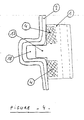
- the figure 4 describes another example of implementation of the device according to the present invention.
- An essential feature of the invention lies in the very design of the device so that it can be fixed to the metal profile and maintain it in a vertical position from the laying on the ground.
- the fixing system can be varied: mechanical fixing, clips or preferably magnetization to take advantage of the magnetic characteristics of the steel.
- the figure 1 gives an example of the device according to the invention in one of its preferred forms. It is about any block (1) which is fixed on the profile (2) by a magnet (4).
- the block (1) is provided with a hole or hole (3) for sliding a threaded rod (5) fixed to a support (6).
- a nut (7) keeps the block (1) up.
- the support (6) is placed on the ground, the profile (2) is automatically placed in a good position, preferably vertical.
- the nut (7) is used to adjust the upper level of the profile (2) without changing the verticality.
- the material constituting the block (1) is unimportant: it can be metal, resin, synthetic, plastic, ... without limitation of the invention.
- the figure 2 shows another preferred form of the device according to the invention.
- the block (1) is provided with two magnets (4) and a protrusion (8) that can enter a reservation (9) provided in the profile (2).
- the nut has been advantageously replaced by a larger piece (10) of suitable shape for manual handling without tools.
- the figure 3 shows different fixing means that can replace the magnets (4).
- the block (1) is provided with one or more threaded reservations (11) and a bolt (12) to set the profile.
- a "clip" fixing device is shown: the block (1) is provided with one or more protuberances (13) whose shape matches a reservation (14) provided in the profile (2).
- the block (1) is provided with a lip (15) lateral or upper as shown here, and perforated to receive a mechanical attachment (16) which can be a bolt, a rivet, or other.
- the figure 4 shows again an example of the device according to the invention.
- the block (1) is provided with two magnets (4) and a protrusion (17) that can enter a reservation (18) made for example by folding profiles (2).
- the method of attachment between the profile and the device of the invention is not a limiting criterion of the invention.
- the device is only designed so that it can maintain the profile to be placed in the expansion joint as soon as it is placed on the floor and to be able to adjust the upper level while keeping it in the correct position.
- the characteristic elements of the invention are the following: it is a device consisting mainly of any block that can be fixed in any way on a profile preferably metal, to maintain the profile in a specific position preferably vertical, as soon as the whole is placed on the floor.
Landscapes
- Engineering & Computer Science (AREA)
- Architecture (AREA)
- Civil Engineering (AREA)
- Structural Engineering (AREA)
- Road Paving Structures (AREA)
Priority Applications (2)
| Application Number | Priority Date | Filing Date | Title |
|---|---|---|---|
| EP07120937A EP2060700A1 (de) | 2007-11-16 | 2007-11-16 | Verlegevorrichtung für Bewegungsfugen |
| EP08169233A EP2060701A1 (de) | 2007-11-16 | 2008-11-17 | Verlegevorrichtung für Bewegungsfugen |
Applications Claiming Priority (1)
| Application Number | Priority Date | Filing Date | Title |
|---|---|---|---|
| EP07120937A EP2060700A1 (de) | 2007-11-16 | 2007-11-16 | Verlegevorrichtung für Bewegungsfugen |
Publications (1)
| Publication Number | Publication Date |
|---|---|
| EP2060700A1 true EP2060700A1 (de) | 2009-05-20 |
Family
ID=39185796
Family Applications (2)
| Application Number | Title | Priority Date | Filing Date |
|---|---|---|---|
| EP07120937A Withdrawn EP2060700A1 (de) | 2007-11-16 | 2007-11-16 | Verlegevorrichtung für Bewegungsfugen |
| EP08169233A Withdrawn EP2060701A1 (de) | 2007-11-16 | 2008-11-17 | Verlegevorrichtung für Bewegungsfugen |
Family Applications After (1)
| Application Number | Title | Priority Date | Filing Date |
|---|---|---|---|
| EP08169233A Withdrawn EP2060701A1 (de) | 2007-11-16 | 2008-11-17 | Verlegevorrichtung für Bewegungsfugen |
Country Status (1)
| Country | Link |
|---|---|
| EP (2) | EP2060700A1 (de) |
Families Citing this family (1)
| Publication number | Priority date | Publication date | Assignee | Title |
|---|---|---|---|---|
| CN105735615B (zh) * | 2016-04-14 | 2018-04-03 | 江苏天目建设集团有限公司 | 柱周楼地面混凝土面层可调式工具化模板 |
Citations (5)
| Publication number | Priority date | Publication date | Assignee | Title |
|---|---|---|---|---|
| FR2320404A1 (fr) * | 1975-08-06 | 1977-03-04 | Bassenne Louis | Regle perfectionnee pour la pose de joints dans le beton frais, avec adaptation pour la pose de joints avant le coulage du beton, et procede d'utilisation |
| EP0568949A1 (de) * | 1992-05-06 | 1993-11-10 | Harry Frey | Vorrichtung zum Trennen der Fussbodenbeläge unter einer Tür |
| DE19942050A1 (de) * | 1999-09-03 | 2001-03-08 | Harry Frey | Bodenschiene |
| DE10300836A1 (de) * | 2003-01-10 | 2004-07-22 | Inge Frey | Bodenschiene |
| DE102005018682A1 (de) * | 2004-04-24 | 2005-11-10 | Inge Frey | Bodenschiene |
Family Cites Families (4)
| Publication number | Priority date | Publication date | Assignee | Title |
|---|---|---|---|---|
| US4904111A (en) * | 1989-02-21 | 1990-02-27 | Cardinal Manufacturing Co. | Adjustable support for use with metal keyway forms for above grade concrete slab |
| EP1783277A1 (de) | 2002-08-16 | 2007-05-09 | Permaban Limited | Betonbodenplatte |
| CH696690A5 (de) * | 2003-01-20 | 2007-09-28 | Damien Mischler | Estricheinbausystem. |
| US8112959B2 (en) | 2006-09-22 | 2012-02-14 | Plakabeton S.A. | Device connecting concrete slabs at an expansion joint |
-
2007
- 2007-11-16 EP EP07120937A patent/EP2060700A1/de not_active Withdrawn
-
2008
- 2008-11-17 EP EP08169233A patent/EP2060701A1/de not_active Withdrawn
Patent Citations (5)
| Publication number | Priority date | Publication date | Assignee | Title |
|---|---|---|---|---|
| FR2320404A1 (fr) * | 1975-08-06 | 1977-03-04 | Bassenne Louis | Regle perfectionnee pour la pose de joints dans le beton frais, avec adaptation pour la pose de joints avant le coulage du beton, et procede d'utilisation |
| EP0568949A1 (de) * | 1992-05-06 | 1993-11-10 | Harry Frey | Vorrichtung zum Trennen der Fussbodenbeläge unter einer Tür |
| DE19942050A1 (de) * | 1999-09-03 | 2001-03-08 | Harry Frey | Bodenschiene |
| DE10300836A1 (de) * | 2003-01-10 | 2004-07-22 | Inge Frey | Bodenschiene |
| DE102005018682A1 (de) * | 2004-04-24 | 2005-11-10 | Inge Frey | Bodenschiene |
Also Published As
| Publication number | Publication date |
|---|---|
| EP2060701A1 (de) | 2009-05-20 |
Similar Documents
| Publication | Publication Date | Title |
|---|---|---|
| CA2863791C (fr) | Systeme de fixation d'un panneau sur un element de structure porteuse | |
| EP0953682A1 (de) | Verbindungsanordnung für Platten aus formbarem Material | |
| FR3005480A3 (fr) | Ensemble de porte | |
| CA2060841A1 (fr) | Dispositif pour le maintien provisoire d'un organe de levage sur une surface metallique de coffrage pendant les phases de coulee et de prise du beton d'un element en beton prefabrique | |
| FR3021985A1 (fr) | Dispositif de raccordement a stabilite amelioree | |
| EP2060701A1 (de) | Verlegevorrichtung für Bewegungsfugen | |
| EP4060143B1 (de) | Bauelement | |
| EP3321446A1 (de) | Hilfsstütze für die verlegung von bodenelementen wie bodenplatten, doppelbodensystem, das diese umfasst, und verfahren zu deren verwendung | |
| FR2952413A1 (fr) | Dispositif pour la fixation d'une piece rapportee s'appuyant de l'exterieur par rapport a la tole de carrosserie exterieure d'une carosserie de vehicule. | |
| FR3089236A1 (fr) | Entretoise pour remplacement de rails de chemin de fer | |
| FR3111652A1 (fr) | Pige de nivellement amelioree pour chape de beton | |
| EP2907630B1 (de) | Mobiler Anschlag für eine Vorrichtung zum Schneiden vom Platten und Schneidvorrichtung mit dem Anschlag | |
| EP0621382A2 (de) | Befestigung von Fliesen oder Platten für hinterlüftete Wandbeläge | |
| EP2381034B1 (de) | Vorrichtung zum Einrichten einer Dehnungsfuge zwischen Betonplatten | |
| FR3067736B1 (fr) | Cadre de menuiserie | |
| FR2896020A1 (fr) | Dispositif de fixation et de reglage d'une piece sur un support | |
| FR2922741A1 (fr) | Attache reglable securisee de longueur adaptable | |
| FR2587261A1 (fr) | Mordache a fixation elastique | |
| FR2852335A1 (fr) | Procede de realisation d'une voie de type plate-forme circulable | |
| CH466548A (fr) | Dispositif de fixation notamment d'un coffrage en reprise | |
| BE1004039A5 (fr) | Brique de revetement en matiere ceramique refractaire. | |
| FR2718774A1 (fr) | Plinthe préfabriquée et son procédé de mise en place. | |
| EP2216442B1 (de) | Vorrichtung zur Ausstattung einer Dehnungsfuge, insbesondere einer Dehnungsfuge zwischen Betonplatten | |
| EP3085851B1 (de) | Konsole und verfahren zum erstellen einer mauer mit dieser konsole | |
| FR3061922A1 (fr) | Systeme de fixation pour poteau |
Legal Events
| Date | Code | Title | Description |
|---|---|---|---|
| PUAI | Public reference made under article 153(3) epc to a published international application that has entered the european phase |
Free format text: ORIGINAL CODE: 0009012 |
|
| AK | Designated contracting states |
Kind code of ref document: A1 Designated state(s): AT BE BG CH CY CZ DE DK EE ES FI FR GB GR HU IE IS IT LI LT LU LV MC MT NL PL PT RO SE SI SK TR |
|
| AX | Request for extension of the european patent |
Extension state: AL BA HR MK RS |
|
| AKX | Designation fees paid | ||
| REG | Reference to a national code |
Ref country code: DE Ref legal event code: 8566 |
|
| STAA | Information on the status of an ep patent application or granted ep patent |
Free format text: STATUS: THE APPLICATION IS DEEMED TO BE WITHDRAWN |
|
| 18D | Application deemed to be withdrawn |
Effective date: 20091121 |