EP2060730B1 - Dispositif d'étanchéité avec joint d'étanchéité mobil attaché à un ou plusieurs éléments de fixation - Google Patents
Dispositif d'étanchéité avec joint d'étanchéité mobil attaché à un ou plusieurs éléments de fixation Download PDFInfo
- Publication number
- EP2060730B1 EP2060730B1 EP08019842.7A EP08019842A EP2060730B1 EP 2060730 B1 EP2060730 B1 EP 2060730B1 EP 08019842 A EP08019842 A EP 08019842A EP 2060730 B1 EP2060730 B1 EP 2060730B1
- Authority
- EP
- European Patent Office
- Prior art keywords
- seal
- sealing
- profile
- door leaf
- sealing strip
- Prior art date
- Legal status (The legal status is an assumption and is not a legal conclusion. Google has not performed a legal analysis and makes no representation as to the accuracy of the status listed.)
- Active
Links
Images


Classifications
-
- E—FIXED CONSTRUCTIONS
- E06—DOORS, WINDOWS, SHUTTERS, OR ROLLER BLINDS IN GENERAL; LADDERS
- E06B—FIXED OR MOVABLE CLOSURES FOR OPENINGS IN BUILDINGS, VEHICLES, FENCES OR LIKE ENCLOSURES IN GENERAL, e.g. DOORS, WINDOWS, BLINDS, GATES
- E06B7/00—Special arrangements or measures in connection with doors or windows
- E06B7/16—Sealing arrangements on wings or parts co-operating with the wings
- E06B7/18—Sealing arrangements on wings or parts co-operating with the wings by means of movable edgings, e.g. draught sealings additionally used for bolting, e.g. by spring force or with operating lever
- E06B7/20—Sealing arrangements on wings or parts co-operating with the wings by means of movable edgings, e.g. draught sealings additionally used for bolting, e.g. by spring force or with operating lever automatically withdrawn when the wing is opened, e.g. by means of magnetic attraction, a pin or an inclined surface, especially for sills
- E06B7/215—Sealing arrangements on wings or parts co-operating with the wings by means of movable edgings, e.g. draught sealings additionally used for bolting, e.g. by spring force or with operating lever automatically withdrawn when the wing is opened, e.g. by means of magnetic attraction, a pin or an inclined surface, especially for sills with sealing strip being moved to a retracted position by elastic means, e.g. springs
Definitions
- the present invention relates to a gasket for sealing a movable door sash, window sash or the like to a fixed means, for example the floor, the ceiling, a wall, a frame or a frame and an arrangement of a door leaf, sash or the like and such a seal ,
- a seal of the aforementioned type which has a holding means in the form of a housing profile.
- a sealing strip is arranged, which is displaceably mounted on the housing profile between a rest position and a sealing position.
- the housing profile is suitable and arranged for fastening the seal in a groove or on an outer side of a door leaf, a window sash or the like. Illustrated in the document, however, only use with a door leaf.
- the sealing strip comprises a retaining profile and an elastic sealing profile.
- the sealing profile is provided in the sealing position of the sealing strip with a first portion on the fixed means, d. H. the ground, to lie sealingly.
- the sealing profile has two legs, on which fastening structures are provided, with which the sealing profile is fastened to complementary attachment structures of the retaining profile. By this attachment, a sealing concern of the sealing profile is ensured on the holding profile.
- Trained as a housing profile retaining means includes the sealing strip in the rest position almost completely.
- the housing profile is substantially U-shaped and has in comparison to the connecting web long down reaching Leg. Also on these legs, the sealing profile is sealingly in the sealing position. In order to ensure a sealing contact of the sealing profile in the second sections of the housing profile and the attachment structures on the support profile in the sealing position. A draft or sound or smoke passage through a closed and provided with such a seal door is therefore largely prevented. The bottom air of a door provided with such a seal is sealed.
- a seal that prevents a draft between the sealing strip and the door leaf with the door closed is from the documents DE 30 12 660 A1 known.
- the document DE 16 59 852 A discloses a arranged in a window frame of a window seal which seals the sash and the frame against each other when the window is closed and at the same time prevents a draft between the window frame and the seal therethrough.
- Gaps between a housing profile and a door can arise because the grooves and the housing profiles are subject to tolerances. For door leaves made of metal or plastic profiles, these are production-related. In the case of wooden doors, the grooves have to be milled wider than the housing profile, so that they swell when the climate changes, for example due to moisture of the wood does not pinch the seal.
- a seal which has no housing profile, but instead a holding means on which the sealing strip is slidably mounted.
- the sealing profile of this seal has two legs and a bridge.
- the web forms a first portion of the sealing profile and serves to seal against the ground, provided that the sealing strip is lowered.
- the web serves as attachment of the sealing profile on the holding profile.
- the document DE 203 04 351 U1 shows a mounting of the seal in the groove base, wherein the height of the seal in the untripped state, ie when not lowered sealing strip, corresponds to the depth of the groove.
- This assembly has the disadvantage that the groove must be milled if the door leaf must be shortened.
- the present invention has for its object to propose a seal that can be mounted in a groove or on an outer surface of a door, against the door leaf or window sash or the like seals and at the same time a sufficient seal against the fixed means, d. H. in particular to reach the ground, and in which the sealing profile can be designed simply.
- This object is achieved by a seal with the features of claim 1.
- This seal is suitable and is set up such that, at least in the sealing position of the sealing strip, a second section of both legs of the sealing profile sealingly abuts or rest against at least one groove wall or the outside of the door leaf, window sash or the like.
- the second section (s) may also sealingly rest against a groove wall or outside of the door leaf, window sash or the like beyond the sealing position.
- the second sections for example, when changing from not tripped condition for sealing position on the groove wall or the outside of the door leaf, sash or the like abut sliding.
- the legs have extended projections beyond the fastening structures, which form further second sections of the legs.
- These approaches are outwardly exhibited and ends of these approaches are suitable and arranged to be continuous, i. both in a sealing position of the sealing strip or a rest position of the sealing strip to seal against at least one groove wall, the outside of the door leaf, a cover or the like.
- seal seals the sealing profile against the housing profile or holding means, but directly opposite the door, sash or the like. This can be ensured in the sealing position sealing the sealing profile relative to the door wing on the one hand and the fixed means, ie in particular the ground, on the other.
- the gasket does not necessarily have to be placed in the groove bottom in order to have a seal with the door leaf, casement or the like. This makes it unnecessary to have to mount the grooves in the groove base. Rather, the seal can be mounted at the open end of the groove even with grooves deeper than the seal is high in the untripped condition.
- the seal can in particular be mounted so that the sealing profile does not protrude beyond the edge of the groove in the non-triggered state of the seal and preferably terminates flush with the edge of the groove. This allows seals to be used that have a lower stroke than the seals that must be used when mounting the seal in the groove base.
- a lesser stroke of the sealing strip with the sealing profile is not only advantageous in terms of sound and fire protection.
- a lesser stroke usually leads to a lesser path of the release of the seal during the tripping process.
- a great way of triggering the triggering process is particularly disadvantageous in rebated doors. If the trigger has a long way to go, it generally protrudes laterally beyond the door leaf when the door is open. When closing the door, the shutter can then strike already on the frame mirror. This can damage or even destroy the trigger or the frame mirror.
- the sealing profile is not fastened with the legs on the retaining profile, but with a web connecting the legs.
- the thighs are free thighs.
- the retaining profile has to special guide structures, which are made by angled legs of the retaining profile. Such guide structures are not necessary in the inventive seal.
- the holding means or at least in the sealing position of the sealing strip, the second portion or the second portions with which the sealing profile on the door leaf, the window sash or the like does not overlap.
- the holding means or means may further be designed such that Also, the second portion or the second portions are not overlapped in the rest position of the sealing strip.
- Each leg of the sealing profile which is suitable and arranged to rest on the groove wall or the outside in the sealing position and may have one or more predetermined bending points. At these predetermined kinks can bend the legs of the sealing profile so that he or she rest against the groove wall or the outer surface of the door leaf, sash or the like.
- the predetermined bending points may be provided between the fastening structures and the first section, with which the sealing profile on the fixed part, d. H. especially rests on the ground.
- the second portions may be provided between the attachment structures and the first portion.
- the second section or the second sections may be provided in particular in the region of the predetermined bending points.
- the sealing profile may have a plurality of legs with one or more second sections.
- the seal may have a single retaining means, for example in the form of a housing profile, and this retaining means may be a be bar-shaped profile. It is also possible that the seal has a plurality of holding means, these holding means may be connected to each other. For this purpose, one or more connecting means may be provided.
- the seal may have a mechanism over which the sealing strip is attached to the retaining means or the retaining means.
- Such mechanisms are known in the art in a variety of forms.
- the mechanism of a seal according to the invention may comprise a trigger, with which the mechanism is suitable and adapted to be triggered for transferring the sealing strip from the rest position into the sealing performance.
- the retaining profile of a seal according to the invention may be substantially H-shaped in cross-section.
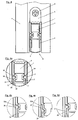
- the recessed in the groove seal D is fixed by means of a bracket 5 and a screw 6 on the door leaf F. By admitting the seal D in the groove, the seal is protected against external influences, in particular mechanical influences.
- a used seal D has a holding means 1, which is formed by a cross-sectionally U-shaped aluminum profile.
- a non-illustrated mechanism 4 is housed, via which the holding means 1 with a sealing strip 2, 3, is connected.
- the sealing strip 2, 3 can be moved relative to the holding means 1 by actuation of the mechanism 4 down.
- the mechanism 4 comprises a trigger, which strikes, for example, when closing the door on a frame of the door and is pressed. The pressing of the trigger then causes the Actuation of the mechanism and thus the lowering of the sealing strip 2, 3.
- the sealing strip 2, 3 comprises a retaining profile 2, also made of aluminum.
- the retaining profile 2 is substantially H-shaped in cross-section and has a web 21, downwardly projecting legs 22 and upwardly projecting legs 23. At the ends of the upwardly projecting legs 23 fastening structures 24 are provided. These attachment structures 24 are used for fastening a sealing profile 3, which also belongs to the sealing strip 2, 3.
- the sealing profile 3 is made of an elastomer, for example made of rubber. It is substantially U-shaped in cross-section and has a web 31 and two legs 39. On the legs 39 attachment structures 35 are attached, which are complementary to the mounting structures 24 of the retaining profile 2 are formed. The fastening structures 24, 35 cooperate to hold the sealing profile 3 on the retaining profile 2.
- the sealing profile 3 serves on the one hand to seal against the bottom B and on the other hand to seal against the door leaf F.
- To seal against the bottom B is the sealing profile 3 in a lowered state, ie in the sealing position, as in FIG. 2 is exemplified, sealingly with the web on the ground.
- the web therefore forms a first portion 31 which is provided for sealing against the bottom B.
- the legs 39 each have second portions 32, which are provided for sealing against the door leaf F and the cover A, W. These second portions 32 are in the in the Figures 1 to 4a illustrated embodiments by Sollknickstellen 33, 34 formed in the legs 39. These predetermined bending points 33, 34, which are provided between the fastening structure 35 and the first section 31 of the sealing profile, effect when abutting the sealing profile 3 in the sealing position (FIG. FIG. 2 ) is a buckling of the leg 39. As a result, the leg is pressed in the second portion 32 to the outside and abuts against the outer wall of the door leaf F or the weatherboard W or the aluminum cover A (see FIG. 2a ).
- seals as in the Figures 1 to 4a is shown seals only in the sealing position, ie with lowered sealing strip 2, 3 with the second portion 32 relative to the outer surface of the door leaf F, the cover A, W or the walls of the groove in the door F from.
- FIGS. 4b to 4d variants shown differ by the shape of the ends of the legs 39 of the sealing profile 3.
- the sealing profile 3 according to the embodiments in Figs Figures 1 to 4a have the legs 39 in the embodiments according to the FIGS. 4b to 4d no predetermined bending points.
- second portions 32, 32 a provided which seal against the outside of the door leaf F or against the cover W, A, or the side walls of the groove in the door leaf F.
- the variants of the invention according to the Figures 4b and 4c have legs with extended beyond the attachment structures 35 addition lugs 36, 37.
- These approaches are issued to the outside and the ends of these lugs 36, 37 dense constantly, ie both in the rest position and in the sealing position of the sealing strip 2, 3 relative to the outer wall of the door leaf, the cover A, W or the side wall of the groove in the door leaf F and form further second sections 32a.
- These other second portions 32a on the flared lugs 36, 37 could also be provided in addition to the predetermined by the predetermined bending point 33, 34 second portions 32.
- a bulge 38 is provided, which forms the second section 32, which seals against the outside of the door leaf F, on the cover A, W or on the side wall of the groove in the door leaf F is present.
- the bulge 38 in the leg is designed so that both in the rest position and in the sealing position of the sealing strip 2, 3 a sealing concern of the sealing profile 3 on the door leaf F or the cover A is guaranteed.
Landscapes
- Engineering & Computer Science (AREA)
- Civil Engineering (AREA)
- Structural Engineering (AREA)
- Specific Sealing Or Ventilating Devices For Doors And Windows (AREA)
Claims (15)
- Dispositif d'étanchéité (D) destiné à l'étanchéification d'un battant de porte (F), d'un battant de fenêtre ou analogue par rapport à un élément immobile, par exemple le sol (B),- avec un ou plusieurs élément(s) de fixation (1),- avec un joint d'étanchéité (2, 3), qui est attaché à l'élément de fixation (1) ou aux éléments de fixation de façon mobile d'une position de repos à une position d'étanchéité,- dans lequel le ou les élément(s) de fixation (1) est/sont approprié(s) et conçu(s) pour la fixation du dispositif d'étanchéité (D) dans une rainure ou sur un côté extérieur d'un battant de porte (F), d'un battant de fenêtre ou analogue,- dans lequel le joint d'étanchéité (2, 3) comprend un profilé de fixation (2) et un profilé d'étanchéité élastique (3),- dans lequel le profilé d'étanchéité (3) est approprié et conçu pour s'appliquer de façon étanche, dans la position d'étanchéité du joint d'étanchéité (2, 3), avec une première partie (31) sur l'élément immobile (B),- dans lequel le profilé d'étanchéité (3) présente deux branches (39), sur lequel ou lesquelles il est prévu des structures de fixation (35), avec lesquelles le profilé d'étanchéité (3) est fixé à des structures de fixation complémentaires (24) du profilé de fixation (2),- dans lequel le profilé d'étanchéité (3) est appliqué ou fixé de façon étanche sur le profilé de fixation (3),- dans lequel le dispositif d'étanchéité (D) est approprié et conçu de telle manière qu'au moins dans la position d'étanchéité du joint d'étanchéité (2, 3), une deuxième partie (32) ou plusieurs deuxièmes parties (32) des deux branches (39) du profilé d'étanchéité (3) s'applique ou s'appliquent sur au moins une paroi de rainure ou sur le côté extérieur du battant de porte (F), du battant de fenêtre ou analogue,caractérisé en ce que
les branches (39) présentent des saillies (36, 37) prolongées au-delà des structures de fixation (35), qui forment d'autres deuxième parties (32a) des branches (39),
les saillies sont étendues vers l'extérieur, et
les extrémités de ces saillies sont appropriées et conçues pour assurer l'étanchéité en permanence, c'est-à-dire aussi bien dans une position d'étanchéité du joint d'étanchéité (2, 3) que dans une position de repos du joint d'étanchéité (2, 3), par rapport à au moins une paroi de rainure, au côté extérieur du battant de porte (F), à une couverture (A, W) ou analogue. - Dispositif d'étanchéité (D) selon la revendication 1, caractérisé en ce que le ou les élément(s) de fixation (1) ne recouvre(nt) pas les deuxièmes parties (32), au moins dans la position d'étanchéité du joint d'étanchéité (2, 3).
- Dispositif d'étanchéité (D) selon la revendication 1 ou 2, caractérisé en ce que le ou les élément(s) de fixation (1) ne recouvre(nt) pas la deuxième partie (32) ou les deuxièmes parties (32) au moins dans la position de repos du joint d'étanchéité (2, 3).
- Dispositif d'étanchéité (D) selon l'une quelconque des revendications 1 à 3, caractérisé en ce qu'une ou chaque branche (39), appropriée et conçue pour s'appliquer, dans la position d'étanchéité, avec la ou les partie(s) (32) sur la paroi de rainure ou sur le côté extérieur, présente un ou plusieurs point(s) de pliage préférentiel(s) (33, 34), auquel ou auxquels les branches (39) du profilé d'étanchéité (3) se plient pour s'appliquer.
- Dispositif d'étanchéité (D) selon la revendication 4, caractérisé en ce que les points de pliage préférentiels (33, 34) sont prévus entre les structures de fixation (35) et la première partie (31).
- Dispositif d'étanchéité (D) selon l'une quelconque des revendications 1 à 5, caractérisé en ce que les deuxièmes parties (32) sont prévues entre les structures de fixation (35) et la première partie (31).
- Dispositif d'étanchéité (D) selon la revendication 5 et 6, caractérisé en ce que les deuxièmes parties (32) sont prévues dans la région des points de pliage préférentiels (33, 34).
- Dispositif d'étanchéité (D) selon l'une quelconque des revendications 1 à 7, caractérisé en ce que l'élément de fixation (1) est un profilé en forme de barre.
- Dispositif d'étanchéité (D) selon l'une quelconque des revendications 1 à 8, caractérisé en ce que le dispositif d'étanchéité (D) présente plusieurs éléments de fixation (1).
- Dispositif d'étanchéité (D) selon la revendication 9, caractérisé en ce que les éléments de fixation (1) sont reliés l'un à l'autre au moyen d'un ou de plusieurs élément(s) de liaison.
- Dispositif d'étanchéité (D) selon l'une quelconque des revendications 1 à 10, caractérisé en ce que le dispositif d'étanchéité (D) présente un mécanisme (4), au moyen duquel le joint d'étanchéité (2, 3) est placé sur l'élément de fixation (1) ou sur les éléments de fixation (1).
- Dispositif d'étanchéité (D) selon la revendication 11, caractérisé en ce que le mécanisme (4) présente au moins un système de libération avec lequel le mécanisme (4) est approprié et conçu pour être libéré en vue du passage du joint d'étanchéité (2, 3) de la position de repos à la position d'étanchéité.
- Dispositif d'étanchéité (D) selon l'une quelconque des revendications 1 à 12, caractérisé en ce que le profilé de fixation (2) présente une section transversale essentiellement en forme de H.
- Agencement composé d'un dispositif d'étanchéité (D) et d'un battant de porte (F), d'un battant de fenêtre ou analogue, caractérisé en ce que le dispositif d'étanchéité (D) est réalisé selon l'une quelconque des revendications 1 à 13.
- Agencement selon la revendication 14, caractérisé en ce que le dispositif d'étanchéité (D) est placé sur le côté extérieur du battant de porte (F) ou du battant de fenêtre et est recouvert par un jet d'eau (W) ou une autre couverture (A).
Applications Claiming Priority (1)
| Application Number | Priority Date | Filing Date | Title |
|---|---|---|---|
| DE200720015974 DE202007015974U1 (de) | 2007-11-14 | 2007-11-14 | Dichtung mit an einem oder mehreren Haltemitteln verschiebbar gelagerter Dichtungsleiste |
Publications (3)
| Publication Number | Publication Date |
|---|---|
| EP2060730A2 EP2060730A2 (fr) | 2009-05-20 |
| EP2060730A3 EP2060730A3 (fr) | 2012-08-29 |
| EP2060730B1 true EP2060730B1 (fr) | 2016-09-07 |
Family
ID=38955300
Family Applications (1)
| Application Number | Title | Priority Date | Filing Date |
|---|---|---|---|
| EP08019842.7A Active EP2060730B1 (fr) | 2007-11-14 | 2008-11-13 | Dispositif d'étanchéité avec joint d'étanchéité mobil attaché à un ou plusieurs éléments de fixation |
Country Status (2)
| Country | Link |
|---|---|
| EP (1) | EP2060730B1 (fr) |
| DE (1) | DE202007015974U1 (fr) |
Families Citing this family (5)
| Publication number | Priority date | Publication date | Assignee | Title |
|---|---|---|---|---|
| DE202011051326U1 (de) | 2011-09-16 | 2012-12-17 | Athmer Ohg | Dichtung für Türen, Fenster oder Ähnlichem mit einer absenkbaren Dichtleiste |
| JP2014114688A (ja) * | 2012-11-14 | 2014-06-26 | Tokyo Man Kk | ドア下端用気密機構、ドア下端用気密機構を有するドア、ドア下端用気密機構を有するドアを含むドアアセンブリ |
| DE102014105529A1 (de) * | 2014-04-17 | 2015-10-22 | Athmer Ohg | Spaltabdichtung |
| DE202015105612U1 (de) * | 2015-10-22 | 2016-11-17 | Rehau Ag + Co. | Flügel eines Fensters oder einer Tür sowie Fenster oder Tür, das/die einen derartigen Flügel umfasst |
| DE102024118145A1 (de) * | 2024-06-26 | 2025-12-31 | ALUMAT Frey GmbH | Abdichtungssystem und Türsystem für eine Pivottür |
Family Cites Families (6)
| Publication number | Priority date | Publication date | Assignee | Title |
|---|---|---|---|---|
| GB176459A (fr) * | ||||
| DE1659852A1 (de) * | 1967-08-12 | 1969-11-06 | Fuchs Otto Metallwerke | Fenster mit einem mindestens um eine Achse rotierbar gelagerten Fluegel |
| DE3012660C2 (de) * | 1980-04-01 | 1985-09-05 | Fa. F. Athmer, 5760 Arnsberg | Vorrichtung zum Abdichten des unteren Spalts einer schwellenlosen Tür |
| DE20208182U1 (de) * | 2002-05-25 | 2003-10-16 | Fa. F. Athmer, 59757 Arnsberg | Dichtungsprofil für eine Türdichtungsvorrichtung sowie Türdichtungsvorrichtung |
| DE20304351U1 (de) | 2003-03-19 | 2003-05-28 | Kross, Manfred, 58644 Iserlohn | Bodendichtung für ein Türblatt |
| DE102006007672A1 (de) * | 2006-02-18 | 2007-08-30 | Roto Frank Ag | Dichtungsanordnung eines Fensters, einer Tür oder dgl. |
-
2007
- 2007-11-14 DE DE200720015974 patent/DE202007015974U1/de not_active Expired - Lifetime
-
2008
- 2008-11-13 EP EP08019842.7A patent/EP2060730B1/fr active Active
Also Published As
| Publication number | Publication date |
|---|---|
| EP2060730A2 (fr) | 2009-05-20 |
| EP2060730A3 (fr) | 2012-08-29 |
| DE202007015974U1 (de) | 2008-01-17 |
Similar Documents
| Publication | Publication Date | Title |
|---|---|---|
| EP3221540B1 (fr) | Dispositif d'étanchéité pour châssis mobile utilisé comme châssis coulissant ou châssis levant-coulissant mobile d'une fenêtre ou d'une porte | |
| DE102009056118A1 (de) | Dichtung, insbesondere für Schiebetüren | |
| EP2060730A2 (fr) | Dispositif d'étanchéité avec joint d'étanchéité mobil attaché à un ou plusieurs éléments de fixation | |
| EP2088275B1 (fr) | Profilé d'étanchéité de côtés, notamment pour profilés de cadre et installations de portes coulissantes en étant équipées | |
| DE102008023500A1 (de) | Tür mit einer Bodendichtung | |
| EP3673136B1 (fr) | Système d'étanchéité pour un battant déplaçable sous la forme d'un battant coulissant ou d'un battant levant-coulissant déplaçable d'une fenêtre ou d'une porte | |
| DE102018114378B4 (de) | Anordnung zur Sicherung von nach innen zu öffnenden Fenstern und Türen gegen Einbrüche | |
| EP3728778B1 (fr) | Vantail de porte doté d'un système d'étanchéité | |
| DE10013719B4 (de) | Verschlusselement | |
| DE202015006206U1 (de) | Dichtungsvorrichtung für einen verschiebbaren Flügel als Schiebeflügel oder verschiebbaren Hebe-Schiebeflügel eines Fensters oder einer Tür | |
| EP1927715A2 (fr) | Profilé pour vantail de fenêtre ou battant de porte | |
| DE20218443U1 (de) | Dichtungssystem für Türen oder Fenster | |
| EP3415706B1 (fr) | Porte | |
| DE102013204944B4 (de) | Elastische Strangdichtung für Fenster, Türen oder dgl. | |
| DE202014100290U1 (de) | Hochwasserschutzsystem | |
| DE202015104997U1 (de) | Führungsvorrichtung für Rollläden | |
| CH714946A2 (de) | Anordnung zum Schutz von Türen oder Fenstern gegen Einbruch. | |
| DE202005021851U1 (de) | Schiebetür | |
| AT508177A2 (de) | Rollladen mit führungsschienen und anschlägen | |
| DE10348963B3 (de) | Hebefenster | |
| EP2333223B1 (fr) | Arrangement d'un joint d'étanchéité pour un battant de fenêtre | |
| DE220001C (fr) | ||
| DE202007010288U1 (de) | Boden-Türdichtung | |
| DE29902673U1 (de) | Fest-Feld | |
| EP3348768A1 (fr) | Dispositif d'étanchéité pour un vantail coulissant en tant que vantail coulissant ou vantail coulissant relevable d'une fenêtre ou d'une porte |
Legal Events
| Date | Code | Title | Description |
|---|---|---|---|
| PUAI | Public reference made under article 153(3) epc to a published international application that has entered the european phase |
Free format text: ORIGINAL CODE: 0009012 |
|
| AK | Designated contracting states |
Kind code of ref document: A2 Designated state(s): AT BE BG CH CY CZ DE DK EE ES FI FR GB GR HR HU IE IS IT LI LT LU LV MC MT NL NO PL PT RO SE SI SK TR |
|
| AX | Request for extension of the european patent |
Extension state: AL BA MK RS |
|
| PUAL | Search report despatched |
Free format text: ORIGINAL CODE: 0009013 |
|
| AK | Designated contracting states |
Kind code of ref document: A3 Designated state(s): AT BE BG CH CY CZ DE DK EE ES FI FR GB GR HR HU IE IS IT LI LT LU LV MC MT NL NO PL PT RO SE SI SK TR |
|
| AX | Request for extension of the european patent |
Extension state: AL BA MK RS |
|
| RIC1 | Information provided on ipc code assigned before grant |
Ipc: E06B 7/18 20060101AFI20120720BHEP Ipc: E06B 7/21 20060101ALI20120720BHEP |
|
| 17P | Request for examination filed |
Effective date: 20130228 |
|
| 17Q | First examination report despatched |
Effective date: 20130328 |
|
| AKX | Designation fees paid |
Designated state(s): AT BE BG CH CY CZ DE DK EE ES FI FR GB GR HR HU IE IS IT LI LT LU LV MC MT NL NO PL PT RO SE SI SK TR |
|
| REG | Reference to a national code |
Ref country code: DE Ref legal event code: R079 Ref document number: 502008014603 Country of ref document: DE Free format text: PREVIOUS MAIN CLASS: E06B0007180000 Ipc: E06B0007215000 |
|
| GRAP | Despatch of communication of intention to grant a patent |
Free format text: ORIGINAL CODE: EPIDOSNIGR1 |
|
| RIC1 | Information provided on ipc code assigned before grant |
Ipc: E06B 7/215 20060101AFI20150922BHEP |
|
| INTG | Intention to grant announced |
Effective date: 20151021 |
|
| GRAP | Despatch of communication of intention to grant a patent |
Free format text: ORIGINAL CODE: EPIDOSNIGR1 |
|
| INTG | Intention to grant announced |
Effective date: 20160518 |
|
| GRAS | Grant fee paid |
Free format text: ORIGINAL CODE: EPIDOSNIGR3 |
|
| GRAA | (expected) grant |
Free format text: ORIGINAL CODE: 0009210 |
|
| AK | Designated contracting states |
Kind code of ref document: B1 Designated state(s): AT BE BG CH CY CZ DE DK EE ES FI FR GB GR HR HU IE IS IT LI LT LU LV MC MT NL NO PL PT RO SE SI SK TR |
|
| REG | Reference to a national code |
Ref country code: GB Ref legal event code: FG4D Free format text: NOT ENGLISH |
|
| REG | Reference to a national code |
Ref country code: CH Ref legal event code: EP |
|
| REG | Reference to a national code |
Ref country code: IE Ref legal event code: FG4D Free format text: LANGUAGE OF EP DOCUMENT: GERMAN |
|
| REG | Reference to a national code |
Ref country code: AT Ref legal event code: REF Ref document number: 827053 Country of ref document: AT Kind code of ref document: T Effective date: 20161015 |
|
| REG | Reference to a national code |
Ref country code: DE Ref legal event code: R096 Ref document number: 502008014603 Country of ref document: DE |
|
| REG | Reference to a national code |
Ref country code: LT Ref legal event code: MG4D |
|
| REG | Reference to a national code |
Ref country code: NL Ref legal event code: MP Effective date: 20160907 |
|
| PG25 | Lapsed in a contracting state [announced via postgrant information from national office to epo] |
Ref country code: LT Free format text: LAPSE BECAUSE OF FAILURE TO SUBMIT A TRANSLATION OF THE DESCRIPTION OR TO PAY THE FEE WITHIN THE PRESCRIBED TIME-LIMIT Effective date: 20160907 Ref country code: NO Free format text: LAPSE BECAUSE OF FAILURE TO SUBMIT A TRANSLATION OF THE DESCRIPTION OR TO PAY THE FEE WITHIN THE PRESCRIBED TIME-LIMIT Effective date: 20161207 Ref country code: FI Free format text: LAPSE BECAUSE OF FAILURE TO SUBMIT A TRANSLATION OF THE DESCRIPTION OR TO PAY THE FEE WITHIN THE PRESCRIBED TIME-LIMIT Effective date: 20160907 Ref country code: HR Free format text: LAPSE BECAUSE OF FAILURE TO SUBMIT A TRANSLATION OF THE DESCRIPTION OR TO PAY THE FEE WITHIN THE PRESCRIBED TIME-LIMIT Effective date: 20160907 |
|
| PG25 | Lapsed in a contracting state [announced via postgrant information from national office to epo] |
Ref country code: NL Free format text: LAPSE BECAUSE OF FAILURE TO SUBMIT A TRANSLATION OF THE DESCRIPTION OR TO PAY THE FEE WITHIN THE PRESCRIBED TIME-LIMIT Effective date: 20160907 Ref country code: ES Free format text: LAPSE BECAUSE OF FAILURE TO SUBMIT A TRANSLATION OF THE DESCRIPTION OR TO PAY THE FEE WITHIN THE PRESCRIBED TIME-LIMIT Effective date: 20160907 Ref country code: LV Free format text: LAPSE BECAUSE OF FAILURE TO SUBMIT A TRANSLATION OF THE DESCRIPTION OR TO PAY THE FEE WITHIN THE PRESCRIBED TIME-LIMIT Effective date: 20160907 Ref country code: GR Free format text: LAPSE BECAUSE OF FAILURE TO SUBMIT A TRANSLATION OF THE DESCRIPTION OR TO PAY THE FEE WITHIN THE PRESCRIBED TIME-LIMIT Effective date: 20161208 Ref country code: BE Free format text: LAPSE BECAUSE OF NON-PAYMENT OF DUE FEES Effective date: 20161130 Ref country code: SE Free format text: LAPSE BECAUSE OF FAILURE TO SUBMIT A TRANSLATION OF THE DESCRIPTION OR TO PAY THE FEE WITHIN THE PRESCRIBED TIME-LIMIT Effective date: 20160907 |
|
| PG25 | Lapsed in a contracting state [announced via postgrant information from national office to epo] |
Ref country code: RO Free format text: LAPSE BECAUSE OF FAILURE TO SUBMIT A TRANSLATION OF THE DESCRIPTION OR TO PAY THE FEE WITHIN THE PRESCRIBED TIME-LIMIT Effective date: 20160907 Ref country code: EE Free format text: LAPSE BECAUSE OF FAILURE TO SUBMIT A TRANSLATION OF THE DESCRIPTION OR TO PAY THE FEE WITHIN THE PRESCRIBED TIME-LIMIT Effective date: 20160907 |
|
| PG25 | Lapsed in a contracting state [announced via postgrant information from national office to epo] |
Ref country code: IS Free format text: LAPSE BECAUSE OF FAILURE TO SUBMIT A TRANSLATION OF THE DESCRIPTION OR TO PAY THE FEE WITHIN THE PRESCRIBED TIME-LIMIT Effective date: 20170107 Ref country code: SK Free format text: LAPSE BECAUSE OF FAILURE TO SUBMIT A TRANSLATION OF THE DESCRIPTION OR TO PAY THE FEE WITHIN THE PRESCRIBED TIME-LIMIT Effective date: 20160907 Ref country code: PL Free format text: LAPSE BECAUSE OF FAILURE TO SUBMIT A TRANSLATION OF THE DESCRIPTION OR TO PAY THE FEE WITHIN THE PRESCRIBED TIME-LIMIT Effective date: 20160907 Ref country code: PT Free format text: LAPSE BECAUSE OF FAILURE TO SUBMIT A TRANSLATION OF THE DESCRIPTION OR TO PAY THE FEE WITHIN THE PRESCRIBED TIME-LIMIT Effective date: 20170109 Ref country code: BG Free format text: LAPSE BECAUSE OF FAILURE TO SUBMIT A TRANSLATION OF THE DESCRIPTION OR TO PAY THE FEE WITHIN THE PRESCRIBED TIME-LIMIT Effective date: 20161207 Ref country code: CZ Free format text: LAPSE BECAUSE OF FAILURE TO SUBMIT A TRANSLATION OF THE DESCRIPTION OR TO PAY THE FEE WITHIN THE PRESCRIBED TIME-LIMIT Effective date: 20160907 |
|
| REG | Reference to a national code |
Ref country code: DE Ref legal event code: R097 Ref document number: 502008014603 Country of ref document: DE |
|
| PG25 | Lapsed in a contracting state [announced via postgrant information from national office to epo] |
Ref country code: IT Free format text: LAPSE BECAUSE OF FAILURE TO SUBMIT A TRANSLATION OF THE DESCRIPTION OR TO PAY THE FEE WITHIN THE PRESCRIBED TIME-LIMIT Effective date: 20160907 |
|
| PLBE | No opposition filed within time limit |
Free format text: ORIGINAL CODE: 0009261 |
|
| STAA | Information on the status of an ep patent application or granted ep patent |
Free format text: STATUS: NO OPPOSITION FILED WITHIN TIME LIMIT |
|
| PG25 | Lapsed in a contracting state [announced via postgrant information from national office to epo] |
Ref country code: DK Free format text: LAPSE BECAUSE OF FAILURE TO SUBMIT A TRANSLATION OF THE DESCRIPTION OR TO PAY THE FEE WITHIN THE PRESCRIBED TIME-LIMIT Effective date: 20160907 |
|
| 26N | No opposition filed |
Effective date: 20170608 |
|
| REG | Reference to a national code |
Ref country code: IE Ref legal event code: MM4A |
|
| REG | Reference to a national code |
Ref country code: FR Ref legal event code: ST Effective date: 20170731 |
|
| PG25 | Lapsed in a contracting state [announced via postgrant information from national office to epo] |
Ref country code: SI Free format text: LAPSE BECAUSE OF FAILURE TO SUBMIT A TRANSLATION OF THE DESCRIPTION OR TO PAY THE FEE WITHIN THE PRESCRIBED TIME-LIMIT Effective date: 20160907 |
|
| PG25 | Lapsed in a contracting state [announced via postgrant information from national office to epo] |
Ref country code: LU Free format text: LAPSE BECAUSE OF NON-PAYMENT OF DUE FEES Effective date: 20161130 |
|
| PG25 | Lapsed in a contracting state [announced via postgrant information from national office to epo] |
Ref country code: FR Free format text: LAPSE BECAUSE OF NON-PAYMENT OF DUE FEES Effective date: 20161130 |
|
| PG25 | Lapsed in a contracting state [announced via postgrant information from national office to epo] |
Ref country code: IE Free format text: LAPSE BECAUSE OF NON-PAYMENT OF DUE FEES Effective date: 20161113 |
|
| REG | Reference to a national code |
Ref country code: BE Ref legal event code: MM Effective date: 20161130 |
|
| PG25 | Lapsed in a contracting state [announced via postgrant information from national office to epo] |
Ref country code: HU Free format text: LAPSE BECAUSE OF FAILURE TO SUBMIT A TRANSLATION OF THE DESCRIPTION OR TO PAY THE FEE WITHIN THE PRESCRIBED TIME-LIMIT; INVALID AB INITIO Effective date: 20081113 Ref country code: CY Free format text: LAPSE BECAUSE OF FAILURE TO SUBMIT A TRANSLATION OF THE DESCRIPTION OR TO PAY THE FEE WITHIN THE PRESCRIBED TIME-LIMIT Effective date: 20160907 |
|
| PG25 | Lapsed in a contracting state [announced via postgrant information from national office to epo] |
Ref country code: TR Free format text: LAPSE BECAUSE OF FAILURE TO SUBMIT A TRANSLATION OF THE DESCRIPTION OR TO PAY THE FEE WITHIN THE PRESCRIBED TIME-LIMIT Effective date: 20160907 Ref country code: MC Free format text: LAPSE BECAUSE OF FAILURE TO SUBMIT A TRANSLATION OF THE DESCRIPTION OR TO PAY THE FEE WITHIN THE PRESCRIBED TIME-LIMIT Effective date: 20160907 |
|
| PG25 | Lapsed in a contracting state [announced via postgrant information from national office to epo] |
Ref country code: MT Free format text: LAPSE BECAUSE OF FAILURE TO SUBMIT A TRANSLATION OF THE DESCRIPTION OR TO PAY THE FEE WITHIN THE PRESCRIBED TIME-LIMIT Effective date: 20160907 |
|
| P01 | Opt-out of the competence of the unified patent court (upc) registered |
Effective date: 20230616 |
|
| PGFP | Annual fee paid to national office [announced via postgrant information from national office to epo] |
Ref country code: AT Payment date: 20241121 Year of fee payment: 17 |
|
| REG | Reference to a national code |
Ref country code: CH Ref legal event code: U11 Free format text: ST27 STATUS EVENT CODE: U-0-0-U10-U11 (AS PROVIDED BY THE NATIONAL OFFICE) Effective date: 20251201 |
|
| PGFP | Annual fee paid to national office [announced via postgrant information from national office to epo] |
Ref country code: DE Payment date: 20251130 Year of fee payment: 18 |
|
| PGFP | Annual fee paid to national office [announced via postgrant information from national office to epo] |
Ref country code: GB Payment date: 20251121 Year of fee payment: 18 |
|
| PGFP | Annual fee paid to national office [announced via postgrant information from national office to epo] |
Ref country code: CH Payment date: 20251201 Year of fee payment: 18 |