EP2060736A2 - Mecanisme permettant de faire tomber plusieurs boulets dans des tubages utilises dans le forage, la completion et le reconditionnement des puits - Google Patents
Mecanisme permettant de faire tomber plusieurs boulets dans des tubages utilises dans le forage, la completion et le reconditionnement des puits Download PDFInfo
- Publication number
- EP2060736A2 EP2060736A2 EP09154301A EP09154301A EP2060736A2 EP 2060736 A2 EP2060736 A2 EP 2060736A2 EP 09154301 A EP09154301 A EP 09154301A EP 09154301 A EP09154301 A EP 09154301A EP 2060736 A2 EP2060736 A2 EP 2060736A2
- Authority
- EP
- European Patent Office
- Prior art keywords
- ball
- sub
- tubular string
- interior passage
- mandrel
- Prior art date
- Legal status (The legal status is an assumption and is not a legal conclusion. Google has not performed a legal analysis and makes no representation as to the accuracy of the status listed.)
- Withdrawn
Links
Images

Classifications
-
- E—FIXED CONSTRUCTIONS
- E21—EARTH OR ROCK DRILLING; MINING
- E21B—EARTH OR ROCK DRILLING; OBTAINING OIL, GAS, WATER, SOLUBLE OR MELTABLE MATERIALS OR A SLURRY OF MINERALS FROM WELLS
- E21B33/00—Sealing or packing boreholes or wells
- E21B33/02—Surface sealing or packing
- E21B33/03—Well heads; Setting-up thereof
- E21B33/04—Casing heads; Suspending casings or tubings in well heads
- E21B33/05—Cementing-heads, e.g. having provision for introducing cementing plugs
-
- E—FIXED CONSTRUCTIONS
- E21—EARTH OR ROCK DRILLING; MINING
- E21B—EARTH OR ROCK DRILLING; OBTAINING OIL, GAS, WATER, SOLUBLE OR MELTABLE MATERIALS OR A SLURRY OF MINERALS FROM WELLS
- E21B33/00—Sealing or packing boreholes or wells
- E21B33/10—Sealing or packing boreholes or wells in the borehole
- E21B33/13—Methods or devices for cementing, for plugging holes, crevices or the like
- E21B33/14—Methods or devices for cementing, for plugging holes, crevices or the like for cementing casings into boreholes
- E21B33/16—Methods or devices for cementing, for plugging holes, crevices or the like for cementing casings into boreholes using plugs for isolating cement charge; Plugs therefor
- E21B33/165—Cementing plugs specially adapted for being released down-hole
-
- E—FIXED CONSTRUCTIONS
- E21—EARTH OR ROCK DRILLING; MINING
- E21B—EARTH OR ROCK DRILLING; OBTAINING OIL, GAS, WATER, SOLUBLE OR MELTABLE MATERIALS OR A SLURRY OF MINERALS FROM WELLS
- E21B33/00—Sealing or packing boreholes or wells
- E21B33/02—Surface sealing or packing
- E21B33/03—Well heads; Setting-up thereof
- E21B33/068—Well heads; Setting-up thereof having provision for introducing objects or fluids into, or removing objects from, wells
Definitions
- This invention relates generally to equipment used in the drilling, completion and workover of subterranean wells and more specifically, to equipment for use in oilfield tubulars, for example, in casing strings which are cemented in place in earth boreholes drilled into earth formations.
- the controlled dropping of one or more balls into the top portion of a tubular at the earth's surface is therefore very important, both as to the diameter of the ball or balls, and the timing of the release of the ball or balls.
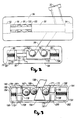
- FIG 1 illustrates, pictorially, the overall apparatus for practicing the present invention.
- the apparatus includes a ball-dropping assembly 64 (shown in more detail in Figure 2 ), and a cement port 66 which can be used in cementing operations.
- the apparatus 54 is a two-ball device, in which two round balls of different diameters 68 and 70 are located in a movable ball carrier 72.
- An air cylinder plunger 74 passing through an air cylinder seal 75, has a first end attached to the ball carrier 72 and a second end attached to a piston 76 which moves within the cylinder 78.
- a return spring 80 is connected between the piston 76 and the end wall of cylinder 78.
- a second return spring 82 is connected between the other end of the ball carrier 72 and the other end of the chamber 78a within the interior of the apparatus 64.
- a pressure source either pneumatic or hydraulic (not illustrated), is connected to the port 88 and the same pressure source, if desired, is connected to the port 90, enabling the piston 76 to be moved in either direction.
- a sub 84 located within the tubular string as illustrated in Figure 1 , immediately across from the apparatus 64, has a tubular ball port 86 through which the balls 68 and 70 can be dropped into the interior passage 88 of the sub 84.
- the sub 84 also includes a pump-in port 90 in fluid communication with the passage 88 and a pair of threaded box connections 92 and 94 at opposite ends of the sub 84.
- Also included in passage 88 is a valve retainer sleeve 96, a lower valve seal 98, a ball valve 100, and an upper valve sleeve 102.
- Figure 3 illustrates, schematically, an alternative embodiment of a ball-dropping mechanism 164 which can be used to drop three different diameter balls 166,168 and 170 through the ball port 186.
- the ball port 186 is coupled into the sub 84 illustrated in Figure 1 , and in so doing, the ball-dropping mechanism 164 substitutes for the two ball, ball-dropping mechanism 64.
- the ball-dropping mechanism 164 has an interior chamber 172 through which a ball carrier 174 can traverse to align the receptacles 167,169 and 171 with the ball port 186.
- a first piston 176 having a shaft 178 attached to one end of the ball carrier 174 and passing through a seal 181, is adapted to traverse the cylinder 180, the cylinder 180 merely being the end portion of the chamber 172.
- a return spring 182 is connected between the piston 176 and the outer housing 184.
- a return spring 194 is connected between the piston 188 and the outer housing 184, surrounding the chamber 172.
- a pair of ports 196 and 198 are provided in the housing 184 on opposite sides of the piston 176 to allow a conventional pressure source (not illustrated), usually pneumatic, to drive the piston 176 one way or the other.
- a second pair of piston ports 200 and 202 are provided in the housing 184 on opposite sides of the piston 188 to allow a conventional pressure source (not illustrated) to drive the piston 188 one way or the other.
- air pressure can be applied to the ports 200 and 196 while venting the ports 202 and 198 to the atmosphere to complete the desired alignment and drop the ball 168 into the ball port 186.
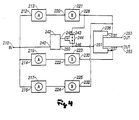
- the input 210 is also connected to an input 240 of a pneumatic valve 242.
- the output 228 of valve 221 is connected into an input 244, whose output is connected to a second input 248 of valve 242.
- the output 250 of the valve 242 is connected to a second input 246 of switch 244.
- the pressurized air from output 250 of valve 242 is also found at input 251 of the pneumatic valve 236, a two-position valve which supplies pressurized air either from output 253 or output 255, but not both simultaneously.
- the output 253 of Figure 4 is connected to the port 196 in Figure 3 .
- the output 255 of Figure 4 is connected to the port 202 of Figure 3 .
- the system of Figures 3 and 4 have the feature that in dropping the three balls, 166,168 and 170, only the smallest ball 168 can be dropped first. If the "A" and “B” buttons of valves 215 and 223, and/or the “A” and “B” buttons of valves 217 and 225 are depressed first, by accident or otherwise, nothing will happen because the pressurized air is blocked from passing through the valve 242 and hence, through the valve 236.
- valves 214 and 222 are depressed, causing the pressurized air to flow from the output 255 of valve 236, and into the port 202. This causes the ball carrier 174 to move laterally, aligning the ball 170 with the ball port 186, causing the ball 170 to be dropped.
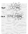
- a safety pin 83 is illustrated as being connected to the end wall 85 of housing 84.
- the pin 83 is slidably moveable through the sidewall 73 of the pocket containing the ball 70, and protrudes slightly into the pocket space.
Landscapes
- Life Sciences & Earth Sciences (AREA)
- Engineering & Computer Science (AREA)
- Geology (AREA)
- Mining & Mineral Resources (AREA)
- Physics & Mathematics (AREA)
- Environmental & Geological Engineering (AREA)
- Fluid Mechanics (AREA)
- General Life Sciences & Earth Sciences (AREA)
- Geochemistry & Mineralogy (AREA)
- Earth Drilling (AREA)
Applications Claiming Priority (3)
| Application Number | Priority Date | Filing Date | Title |
|---|---|---|---|
| US13204499P | 1999-04-30 | 1999-04-30 | |
| US09/559,241 US6302199B1 (en) | 1999-04-30 | 2000-04-26 | Mechanism for dropping a plurality of balls into tubulars used in drilling, completion and workover of oil, gas and geothermal wells |
| EP00978197A EP1101012B1 (fr) | 1999-04-30 | 2000-04-26 | Mecanisme permettant de faire tomber plusieurs boulets dans des tubages utilises dans le forage, la completion et le reconditionnement des puits de petrole, de gaz et geothermiques, et procede d'utilisation |
Related Parent Applications (2)
| Application Number | Title | Priority Date | Filing Date |
|---|---|---|---|
| EP00978197A Division EP1101012B1 (fr) | 1999-04-30 | 2000-04-26 | Mecanisme permettant de faire tomber plusieurs boulets dans des tubages utilises dans le forage, la completion et le reconditionnement des puits de petrole, de gaz et geothermiques, et procede d'utilisation |
| EP00978197.2 Division | 2000-04-26 |
Publications (2)
| Publication Number | Publication Date |
|---|---|
| EP2060736A2 true EP2060736A2 (fr) | 2009-05-20 |
| EP2060736A3 EP2060736A3 (fr) | 2013-09-18 |
Family
ID=46149854
Family Applications (1)
| Application Number | Title | Priority Date | Filing Date |
|---|---|---|---|
| EP09154301.7A Withdrawn EP2060736A3 (fr) | 1999-04-30 | 2000-04-26 | Mecanisme permettant de faire tomber plusieurs boulets dans des tubages utilises dans le forage, la completion et le reconditionnement des puits |
Country Status (1)
| Country | Link |
|---|---|
| EP (1) | EP2060736A3 (fr) |
Cited By (1)
| Publication number | Priority date | Publication date | Assignee | Title |
|---|---|---|---|---|
| US9528356B2 (en) | 2014-03-05 | 2016-12-27 | Halliburton Energy Services Inc. | Flow control mechanism for downhole tool |
Family Cites Families (3)
| Publication number | Priority date | Publication date | Assignee | Title |
|---|---|---|---|---|
| US5095988A (en) * | 1989-11-15 | 1992-03-17 | Bode Robert E | Plug injection method and apparatus |
| US5918673A (en) * | 1996-10-04 | 1999-07-06 | Frank's International, Inc. | Method and multi-purpose apparatus for dispensing and circulating fluid in wellbore casing |
| US5735348A (en) * | 1996-10-04 | 1998-04-07 | Frank's International, Inc. | Method and multi-purpose apparatus for dispensing and circulating fluid in wellbore casing |
-
2000
- 2000-04-26 EP EP09154301.7A patent/EP2060736A3/fr not_active Withdrawn
Cited By (1)
| Publication number | Priority date | Publication date | Assignee | Title |
|---|---|---|---|---|
| US9528356B2 (en) | 2014-03-05 | 2016-12-27 | Halliburton Energy Services Inc. | Flow control mechanism for downhole tool |
Also Published As
| Publication number | Publication date |
|---|---|
| EP2060736A3 (fr) | 2013-09-18 |
Similar Documents
| Publication | Publication Date | Title |
|---|---|---|
| US6302199B1 (en) | Mechanism for dropping a plurality of balls into tubulars used in drilling, completion and workover of oil, gas and geothermal wells | |
| US6401826B2 (en) | Lubricator for underbalanced drilling | |
| US6467546B2 (en) | Drop ball sub and system of use | |
| US4494608A (en) | Well injection system | |
| US9777558B1 (en) | Methods and devices for one trip plugging and perforating of oil and gas wells | |
| CA2442981C (fr) | Siege de rotule a ouverture mecanique et siege de rotule expansible | |
| US6772839B1 (en) | Method and apparatus for mechanically perforating a well casing or other tubular structure for testing, stimulation or other remedial operations | |
| US7143831B2 (en) | Apparatus for releasing a ball into a wellbore | |
| US20100089587A1 (en) | Fluid logic tool for a subterranean well | |
| US5372193A (en) | Completion test tool | |
| US7108071B2 (en) | Automatic tubing filler | |
| US20110155392A1 (en) | Hydrostatic Flapper Stimulation Valve and Method | |
| CA2715250C (fr) | Systeme pour forer des puits en sous-pression | |
| US6024173A (en) | Inflatable shifting tool | |
| US9103184B2 (en) | Inflow control valve | |
| EP1608839B1 (fr) | Procede et appareil pour achever un puits dans lequel un tubage est insere par une vanne | |
| NL2019726B1 (en) | Top-down squeeze system and method | |
| US3572434A (en) | Pressure opened circulating sleeve | |
| EP2060736A2 (fr) | Mecanisme permettant de faire tomber plusieurs boulets dans des tubages utilises dans le forage, la completion et le reconditionnement des puits | |
| EP0543642A2 (fr) | Dispositif d'étanchéité au fond de puits | |
| WO1997005759A2 (fr) | Dispositif ameliore pour le fond d'un trou de forage | |
| US20150101809A1 (en) | Piston float equipment | |
| GB2388140A (en) | Downhole isolation valve | |
| CA2717595A1 (fr) | Outil de logique a fluide pour puits souterrain |
Legal Events
| Date | Code | Title | Description |
|---|---|---|---|
| PUAI | Public reference made under article 153(3) epc to a published international application that has entered the european phase |
Free format text: ORIGINAL CODE: 0009012 |
|
| AC | Divisional application: reference to earlier application |
Ref document number: 1101012 Country of ref document: EP Kind code of ref document: P |
|
| AK | Designated contracting states |
Kind code of ref document: A2 Designated state(s): AT BE CH CY DE DK ES FI FR GB GR IE IT LI LU MC NL PT SE |
|
| AX | Request for extension of the european patent |
Extension state: AL LT LV MK RO SI |
|
| PUAL | Search report despatched |
Free format text: ORIGINAL CODE: 0009013 |
|
| AK | Designated contracting states |
Kind code of ref document: A3 Designated state(s): DE DK GB NL |
|
| RIC1 | Information provided on ipc code assigned before grant |
Ipc: E21B 33/16 20060101AFI20130814BHEP Ipc: E21B 33/068 20060101ALI20130814BHEP Ipc: E21B 33/05 20060101ALI20130814BHEP |
|
| 17P | Request for examination filed |
Effective date: 20140318 |
|
| RBV | Designated contracting states (corrected) |
Designated state(s): DE DK GB NL |
|
| AKX | Designation fees paid |
Designated state(s): DE DK GB NL |
|
| STAA | Information on the status of an ep patent application or granted ep patent |
Free format text: STATUS: REQUEST FOR EXAMINATION WAS MADE |
|
| STAA | Information on the status of an ep patent application or granted ep patent |
Free format text: STATUS: THE APPLICATION IS DEEMED TO BE WITHDRAWN |
|
| 18D | Application deemed to be withdrawn |
Effective date: 20161101 |