EP2060745B1 - Segment d'étanchéité pour turbine à gaz - Google Patents
Segment d'étanchéité pour turbine à gaz Download PDFInfo
- Publication number
- EP2060745B1 EP2060745B1 EP08253685.5A EP08253685A EP2060745B1 EP 2060745 B1 EP2060745 B1 EP 2060745B1 EP 08253685 A EP08253685 A EP 08253685A EP 2060745 B1 EP2060745 B1 EP 2060745B1
- Authority
- EP
- European Patent Office
- Prior art keywords
- land
- end portion
- cooling passage
- outer air
- air seal
- Prior art date
- Legal status (The legal status is an assumption and is not a legal conclusion. Google has not performed a legal analysis and makes no representation as to the accuracy of the status listed.)
- Active
Links
Images


Classifications
-
- F—MECHANICAL ENGINEERING; LIGHTING; HEATING; WEAPONS; BLASTING
- F01—MACHINES OR ENGINES IN GENERAL; ENGINE PLANTS IN GENERAL; STEAM ENGINES
- F01D—NON-POSITIVE DISPLACEMENT MACHINES OR ENGINES, e.g. STEAM TURBINES
- F01D25/00—Component parts, details, or accessories, not provided for in, or of interest apart from, other groups
- F01D25/08—Cooling; Heating; Heat-insulation
- F01D25/12—Cooling
-
- B—PERFORMING OPERATIONS; TRANSPORTING
- B22—CASTING; POWDER METALLURGY
- B22C—FOUNDRY MOULDING
- B22C21/00—Flasks; Accessories therefor
- B22C21/12—Accessories
- B22C21/14—Accessories for reinforcing or securing moulding materials or cores, e.g. gaggers, chaplets, pins, bars
-
- B—PERFORMING OPERATIONS; TRANSPORTING
- B22—CASTING; POWDER METALLURGY
- B22C—FOUNDRY MOULDING
- B22C9/00—Moulds or cores; Moulding processes
- B22C9/10—Cores; Manufacture or installation of cores
-
- F—MECHANICAL ENGINEERING; LIGHTING; HEATING; WEAPONS; BLASTING
- F01—MACHINES OR ENGINES IN GENERAL; ENGINE PLANTS IN GENERAL; STEAM ENGINES
- F01D—NON-POSITIVE DISPLACEMENT MACHINES OR ENGINES, e.g. STEAM TURBINES
- F01D11/00—Preventing or minimising internal leakage of working-fluid, e.g. between stages
- F01D11/08—Preventing or minimising internal leakage of working-fluid, e.g. between stages for sealing space between rotor blade tips and stator
-
- F—MECHANICAL ENGINEERING; LIGHTING; HEATING; WEAPONS; BLASTING
- F05—INDEXING SCHEMES RELATING TO ENGINES OR PUMPS IN VARIOUS SUBCLASSES OF CLASSES F01-F04
- F05D—INDEXING SCHEME FOR ASPECTS RELATING TO NON-POSITIVE-DISPLACEMENT MACHINES OR ENGINES, GAS-TURBINES OR JET-PROPULSION PLANTS
- F05D2230/00—Manufacture
- F05D2230/20—Manufacture essentially without removing material
- F05D2230/21—Manufacture essentially without removing material by casting
-
- F—MECHANICAL ENGINEERING; LIGHTING; HEATING; WEAPONS; BLASTING
- F05—INDEXING SCHEMES RELATING TO ENGINES OR PUMPS IN VARIOUS SUBCLASSES OF CLASSES F01-F04
- F05D—INDEXING SCHEME FOR ASPECTS RELATING TO NON-POSITIVE-DISPLACEMENT MACHINES OR ENGINES, GAS-TURBINES OR JET-PROPULSION PLANTS
- F05D2240/00—Components
- F05D2240/10—Stators
- F05D2240/11—Shroud seal segments
-
- F—MECHANICAL ENGINEERING; LIGHTING; HEATING; WEAPONS; BLASTING
- F05—INDEXING SCHEMES RELATING TO ENGINES OR PUMPS IN VARIOUS SUBCLASSES OF CLASSES F01-F04
- F05D—INDEXING SCHEME FOR ASPECTS RELATING TO NON-POSITIVE-DISPLACEMENT MACHINES OR ENGINES, GAS-TURBINES OR JET-PROPULSION PLANTS
- F05D2260/00—Function
- F05D2260/20—Heat transfer, e.g. cooling
- F05D2260/221—Improvement of heat transfer
- F05D2260/2212—Improvement of heat transfer by creating turbulence
Definitions
- This invention relates to a turbine engine segment, such as a turbine blade outer seal.
- a turbine blade outer air seal seals radial leakage around blade tips in the gas path of a turbine engine.
- the seal is made in circumferential panels or segments that are hooked to the engine case. These segments form a circular seal around the gas path. Due to the high temperature of the gases coming from the combustor of the turbine engine, BOAS segments are provided with cooling passages through which cooling air flow is passed often in a circumferential direction.
- ceramic cores are used.
- the BOAS segment is cast around the ceramic core and the core is then leached out leaving behind a cooling passage within the BOAS segment.
- These cores are also provided with turbulators, known as trip strips, that create ripples within the cooling passages so as to promote turbulent airflow through the passage, which improves the heat transfer rate and its cooling performance.
- the ceramic cores themselves are formed in a separate die by injecting a ceramic slurry therein.
- the cores remain in the die for some time, until they have developed enough strength to be removed.
- the cores are designed with a land to receive an ejection pin.
- these lands are then reproduced as part of the cooling passage.
- these lands preclude the formation of trip strips at their location. In the past, these lands have been located in the middle portion of the BOAS segment. Due to the absence of trip strips at the location of the land in the middle of the BOAS segment, the BOAS segment becomes susceptible to thermal mechanical fatigue (TMF). TMF may lead to cracking, which reduces the life of the part and is not desirable.
- TMF thermal mechanical fatigue
- US-A-5486090 discloses a turbine engine gas path sealing segment having the features set forth in the preamble of claim 1, A further turbine shroud element is disclosed in US 2007/0237647A .
- the present invention provides a turbine engine gas path sealing segment as set forth in claim 1.
- the invention also provides a method as set forth in claim 9.
- first BOAS segment 14 and second BOAS segment 30 there are shown first BOAS segment 14 and second BOAS segment 30.
- First BOAS segment 14, second BOAS segment 30 as well as other segments form a turbine blade outer air seal, which forms a circular segmented ring around the turbine blade that restricts leakage of turbine gas from the turbine engine gas flow path around the blade tip.
- an exemplary segment such as first BOAS segment 14 is shown.
- First BOAS segment 14 has first end portion 18, middle portion 22 and second end portion 26. Extending from first end portion 18 through middle portion 22 and second end portion 26 are first cooling passages 46 and second cooling passage 70.
- BOAS segments 14 and 30 interface with, but do not communicate with, each other.
- Second BOAS segment 30 has adjoining edge 34, which serves as an interface with first BOAS segment 14.
- the connection between first BOAS segment 14 and second BOAS segment 30 comprises a small gap to allow for thermal growth between the segments. Cooling flow through each BOAS segment exits the segment and combines with the gas path.
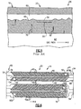
- Figure 2 illustrates a cross-sectional view of first BOAS segment 14.
- first BOAS segment 14 has hooks 74 that allow BOAS segment 14 to be received into a case of a turbine engine.
- BOAS segment 14 when BOAS segment 14 is disposed within the turbine engine case, it is located proximate gas path 62 for the turbine engine. Axial flow from the turbine engine through the gas path 62 is in the direction of arrow A.
- the turbine blades for the turbine engine rotate in the direction of arrow R as shown in Figure 3 .
- FIG. 4 illustrates a plan exposed view of a prior design of a cooling passage, here cooling passage 82.
- cooling passage 82 has first opening 54 on cooling air supply side of BOAS segment and second opening 58 at intersegment edge of BOAS segment.
- Cooling passage 82 extends from first opening 54 to second opening 58 through first end portion 18, middle portion 22 and to second end portion 26.
- turbulating features 66 Disposed within cooling passage 82 are turbulating features 66 for causing turbulent fluid flow through cooling passage 82. These features are commonly known as trip strips.
- land 50 is disposed in middle portion 22 of BOAS segment 14 within cooling passage 82. Land 50 is representative of a portion for receiving a mold ejection pin for a core forming the cooling passage, here cooling passage 82.
- the features 66 help the cooling air remove heat from the BOAS by generating turbulence in the air as well as by increasing the surface area for heat transfer.
- first land 100 is disposed in first end portion 18 while second land 104 is disposed in second end portion 26. Because the cooling flow through first cooling passage 46 is cooler at edges 34 near openings, such as first opening 54, and 'curling/uncurling' of the BOAS segment has less effect on the edges of the BOAS, the absence of trip strips in these areas is less significant. Consequently, turbine engine segment 14 will be less susceptible to thermal mechanical fatigue (TMF) and will have longer life.
- TMF thermal mechanical fatigue
Landscapes
- Engineering & Computer Science (AREA)
- Mechanical Engineering (AREA)
- General Engineering & Computer Science (AREA)
- Turbine Rotor Nozzle Sealing (AREA)
Claims (14)
- Segment d'étanchéité de trajet de gaz de moteur à turbine (14), comprenant :un premier segment d'étanchéité à l'air externe (14) d'aube de turbine ayant une première portion d'extrémité (18), une portion centrale (22) et une seconde portion d'extrémité (26), ledit premier segment d'étanchéité à l'air externe (14) d'aube de turbine étant configuré pour se raccorder à un second segment d'étanchéité à l'air externe (30) d'aube de turbine pour former au moins une partie d'un carénage de rotor de turbine ;un premier passage de refroidissement (82) disposé dans ledit premier segment d'étanchéité à l'air externe (14) d'aube de turbine, ledit premier passage de refroidissement (82) s'étendant de ladite première portion d'extrémité (18) à la seconde portion d'extrémité (26) ; ledit premier passage de refroidissement (82) comprenant une caractéristique de turbulence (66) pour provoquer une turbulence de l'écoulement de fluide dans ledit premier passage de refroidissement (82), ladite caractéristique (66) s'étendant en travers de ladite portion centrale (22) dudit segment d'étanchéité à l'air externe (14) d'aube de turbine ; et caractérisé en ce qu'il comprend en outre :un méplat (50) dans ledit premier passage de refroidissement (82), ledit méplat (50) étant représentatif d'une portion de réception d'une broche d'éjection de moule pour un noyau formant ledit premier passage de refroidissement (84), dans lequel ledit méplat (50) est disposé sur l'une de ladite portion d'extrémité (18) et de ladite seconde portion d'extrémité (26), ladite caractéristique de turbulence (66) étant disposée près dudit méplat (50).
- Segment d'étanchéité de trajet de gaz de moteur à turbine (14) selon la revendication 1, dans lequel ledit premier passage de refroidissement (82) a une première ouverture (54) sur ladite première portion d'extrémité (18) et une seconde ouverture (58) sur ladite seconde portion d'extrémité (26), ledit méplat (50) étant disposé près de l'une de ladite première ouverture (54) et de ladite seconde ouverture (58).
- Segment d'étanchéité de trajet de gaz de moteur à turbine (14) selon la revendication 2, dans lequel l'écoulement de refroidissement sort par ladite seconde ouverture (58) pour gagner un trajet de gaz pour le moteur à turbine.
- Segment d'étanchéité de trajet de gaz de moteur à turbine (14) selon l'une quelconque des revendications précédentes, dans lequel ladite caractéristique comprend une série de bandes d'arrêt (66).
- Segment d'étanchéité de trajet de gaz de moteur à turbine (14) selon l'une quelconque des revendications précédentes, dans lequel ledit premier passage de refroidissement (82) s'étend le long d'une direction de rotation d'un rotor pour le moteur à turbine.
- Ensemble de segment d'étanchéité à l'air externe d'aube de turbine comprenant un segment d'étanchéité de trajet de gaz de moteur à turbine (14) selon l'une quelconque des revendications précédentes et comprenant un second segment d'étanchéité à l'air externe (30) d'aube de turbine, ledit second segment d'étanchéité à l'air externe (30) d'aube de turbine ayant un bord (34) pour faire interface avec ledit premier segment d'étanchéité à l'air externe (14) d'aube de turbine.
- Ensemble de segment d'étanchéité à l'air externe d'aube de turbine selon la revendication 6, dans lequel ledit méplat (50) est situé près dudit bord (34) dudit second segment d'étanchéité à l'air (30) d'aube de turbine.
- Segment ou ensemble d'étanchéité de trajet de gaz de moteur à turbine (14) selon l'une quelconque des revendications précédentes, comprenant un second passage de refroidissement (70), ledit second passage de refroidissement (70) s'étendant de ladite première portion d'extrémité (18) à ladite seconde portion d'extrémité (26), ledit second passage de refroidissement (70) ayant un autre méplat (104), dans lequel ledit méplat (100) est situé sur ladite première portion d'extrémité (18) et ledit un autre méplat (104) est situé sur ladite seconde portion d'extrémité (26).
- Procédé de fabrication d'un segment d'étanchéité à l'air externe (14) d'aube de turbine, le procédé comprenant les étapes consistant à :a) former un passage de refroidissement (82) en travers d'une première portion d'extrémité (18), une première portion centrale (22) et une seconde portion d'extrémité (26) d'un segment d'étanchéité à l'air externe (14) d'aube de turbine ;b) disposer un méplat (50) dans le passage de refroidissement (82), le méplat (50) étant représentatif d'une portion de réception d'une broche d'éjection de moule pour un noyau formant le passage de refroidissement (82) ; etc) disposer des bandes d'arrêt (66) pour créer un écoulement de fluide turbulent dans le passage de refroidissement en travers de la portion centrale (22) ; caractérisé par :d) la localisation du méplat (50) sur l'une de la première portion d'extrémité (18) et de la seconde portion d'extrémité (26).
- Procédé selon la revendication 9, dans lequel le méplat représentatif de la portion de réception d'une broche d'éjection de moule pour un noyau formant le passage de refroidissement comprend un premier méplat (100) et un second méplat (104), le premier méplat (100) étant situé facultativement dans la première portion d'extrémité (18) et le second méplat (104) étant situé facultativement dans la seconde portion d'extrémité (26).
- Procédé selon la revendication 10, dans lequel le premier méplat (100) est situé dans la première portion d'extrémité (18).
- Procédé selon la revendication 11, dans lequel le second méplat (104) est situé dans la seconde portion d'extrémité (26).
- Procédé selon l'une quelconque des revendications 9 à 12, comprenant l'étape de disposition du passage de refroidissement (82) près d'un trajet de gaz.
- Noyau de formation du passage de refroidissement (82) dans le segment d'étanchéité à l'air externe (14) d'aube de turbine selon l'une quelconque des revendications 1 à 8 et comprenant un méplat à broche d'éjection disposé sur la portion dudit noyau qui formera ladite portion d'extrémité (18, 26) dudit passage de refroidissement (82).
Applications Claiming Priority (1)
| Application Number | Priority Date | Filing Date | Title |
|---|---|---|---|
| US11/939,006 US8366383B2 (en) | 2007-11-13 | 2007-11-13 | Air sealing element |
Publications (3)
| Publication Number | Publication Date |
|---|---|
| EP2060745A2 EP2060745A2 (fr) | 2009-05-20 |
| EP2060745A3 EP2060745A3 (fr) | 2012-04-25 |
| EP2060745B1 true EP2060745B1 (fr) | 2013-09-18 |
Family
ID=40202383
Family Applications (1)
| Application Number | Title | Priority Date | Filing Date |
|---|---|---|---|
| EP08253685.5A Active EP2060745B1 (fr) | 2007-11-13 | 2008-11-11 | Segment d'étanchéité pour turbine à gaz |
Country Status (2)
| Country | Link |
|---|---|
| US (1) | US8366383B2 (fr) |
| EP (1) | EP2060745B1 (fr) |
Families Citing this family (15)
| Publication number | Priority date | Publication date | Assignee | Title |
|---|---|---|---|---|
| US9011078B2 (en) * | 2012-01-09 | 2015-04-21 | General Electric Company | Turbine vane seal carrier with slots for cooling and assembly |
| US9103225B2 (en) | 2012-06-04 | 2015-08-11 | United Technologies Corporation | Blade outer air seal with cored passages |
| US9771818B2 (en) | 2012-12-29 | 2017-09-26 | United Technologies Corporation | Seals for a circumferential stop ring in a turbine exhaust case |
| US9963975B2 (en) * | 2015-02-09 | 2018-05-08 | United Technologies Corporation | Trip strip restagger |
| US9863323B2 (en) * | 2015-02-17 | 2018-01-09 | General Electric Company | Tapered gas turbine segment seals |
| US10689998B2 (en) | 2015-10-14 | 2020-06-23 | General Electric Company | Shrouds and methods for forming turbine components |
| US20170175574A1 (en) * | 2015-12-16 | 2017-06-22 | General Electric Company | Method for metering micro-channel circuit |
| US10378380B2 (en) | 2015-12-16 | 2019-08-13 | General Electric Company | Segmented micro-channel for improved flow |
| US11193386B2 (en) * | 2016-05-18 | 2021-12-07 | Raytheon Technologies Corporation | Shaped cooling passages for turbine blade outer air seal |
| US10502093B2 (en) * | 2017-12-13 | 2019-12-10 | Pratt & Whitney Canada Corp. | Turbine shroud cooling |
| US10570773B2 (en) | 2017-12-13 | 2020-02-25 | Pratt & Whitney Canada Corp. | Turbine shroud cooling |
| US11274569B2 (en) | 2017-12-13 | 2022-03-15 | Pratt & Whitney Canada Corp. | Turbine shroud cooling |
| US10533454B2 (en) | 2017-12-13 | 2020-01-14 | Pratt & Whitney Canada Corp. | Turbine shroud cooling |
| US11022002B2 (en) * | 2018-06-27 | 2021-06-01 | Raytheon Technologies Corporation | Attachment body for blade outer air seal |
| US11365645B2 (en) | 2020-10-07 | 2022-06-21 | Pratt & Whitney Canada Corp. | Turbine shroud cooling |
Family Cites Families (18)
| Publication number | Priority date | Publication date | Assignee | Title |
|---|---|---|---|---|
| US4073609A (en) | 1976-08-19 | 1978-02-14 | Mercury Machine Company | Apparatus for molding irregular shapes |
| US4489469A (en) | 1983-04-18 | 1984-12-25 | Williams International Corporation | Process for the production of gas turbine engine rotors and stators |
| JPS60174242A (ja) | 1984-02-17 | 1985-09-07 | Fuso Light Alloys Co Ltd | ダイカスト製品の押出方法及び押出装置 |
| JPS62286657A (ja) | 1986-06-05 | 1987-12-12 | Tohoku Daikiyasuto Kogyosho:Goushi | ヒ−トシンクの製造方法 |
| US5069265A (en) | 1989-01-25 | 1991-12-03 | Pcc Airfoils, Inc. | Method of making a turbine engine component |
| US5052889A (en) * | 1990-05-17 | 1991-10-01 | Pratt & Whintey Canada | Offset ribs for heat transfer surface |
| US5243759A (en) | 1991-10-07 | 1993-09-14 | United Technologies Corporation | Method of casting to control the cooling air flow rate of the airfoil trailing edge |
| US5465780A (en) | 1993-11-23 | 1995-11-14 | Alliedsignal Inc. | Laser machining of ceramic cores |
| US5486090A (en) | 1994-03-30 | 1996-01-23 | United Technologies Corporation | Turbine shroud segment with serpentine cooling channels |
| US5431537A (en) | 1994-04-19 | 1995-07-11 | United Technologies Corporation | Cooled gas turbine blade |
| US5538393A (en) * | 1995-01-31 | 1996-07-23 | United Technologies Corporation | Turbine shroud segment with serpentine cooling channels having a bend passage |
| US5820774A (en) | 1996-10-28 | 1998-10-13 | United Technologies Corporation | Ceramic core for casting a turbine blade |
| US5950705A (en) | 1996-12-03 | 1999-09-14 | General Electric Company | Method for casting and controlling wall thickness |
| US6331098B1 (en) * | 1999-12-18 | 2001-12-18 | General Electric Company | Coriolis turbulator blade |
| EP1247602B1 (fr) | 2001-04-04 | 2008-02-20 | Siemens Aktiengesellschaft | Procédé pour la fabrication d'une aube de turbine |
| US7306424B2 (en) * | 2004-12-29 | 2007-12-11 | United Technologies Corporation | Blade outer seal with micro axial flow cooling system |
| US7448850B2 (en) | 2006-04-07 | 2008-11-11 | General Electric Company | Closed loop, steam cooled turbine shroud |
| US20080005903A1 (en) * | 2006-07-05 | 2008-01-10 | United Technologies Corporation | External datum system and film hole positioning using core locating holes |
-
2007
- 2007-11-13 US US11/939,006 patent/US8366383B2/en active Active
-
2008
- 2008-11-11 EP EP08253685.5A patent/EP2060745B1/fr active Active
Also Published As
| Publication number | Publication date |
|---|---|
| US20090123266A1 (en) | 2009-05-14 |
| US8366383B2 (en) | 2013-02-05 |
| EP2060745A2 (fr) | 2009-05-20 |
| EP2060745A3 (fr) | 2012-04-25 |
Similar Documents
| Publication | Publication Date | Title |
|---|---|---|
| US8366383B2 (en) | Air sealing element | |
| JP4948797B2 (ja) | ガスタービンエンジンロータブレードを冷却するための方法及び装置 | |
| EP3121382B1 (fr) | Moteurs à turbine à gaz comprenant crochets refroidis par des canaux permettant de retenir une partie par rapport à une structure de carter de moteur | |
| EP2071126B1 (fr) | Aubes de turbine et procédé pour fabrication | |
| EP1820937B1 (fr) | Pale de turbine dotée de canaux radiaux de refroidissement | |
| JP4733306B2 (ja) | ろう付け無し隅肉を用いるタービンノズル | |
| US10415403B2 (en) | Cooled blisk for gas turbine engine | |
| JP4731238B2 (ja) | ガスタービンエンジンロータブレードを冷却するための装置 | |
| US6915840B2 (en) | Methods and apparatus for fabricating turbine engine airfoils | |
| US10247015B2 (en) | Cooled blisk with dual wall blades for gas turbine engine | |
| US20130051989A1 (en) | Turbine shroud segment with integrated seal | |
| US7918647B1 (en) | Turbine airfoil with flow blocking insert | |
| EP2942485B1 (fr) | Composant de turbine à gaz avec pointe refroidie au bord de fuite | |
| US11927110B2 (en) | Component for a turbine engine with a cooling hole | |
| JP2001107702A (ja) | 断熱コーティングされたスクィーラ先端空洞 | |
| CN112343665B (zh) | 具有冷却孔的发动机构件 | |
| US20200088037A1 (en) | Turbine engine with annular cavity | |
| US10364683B2 (en) | Gas turbine engine component cooling passage turbulator | |
| EP3294994B1 (fr) | Segment d'aube directrice de turbine à gaz et procédé de fabrication | |
| US10036284B2 (en) | Rotating gas turbine blade and gas turbine with such a blade | |
| EP2947280B1 (fr) | Buses de turbine et systèmes de refroidissement pour joint de glissement de refroidissement | |
| US11333042B2 (en) | Turbine blade with dust tolerant cooling system | |
| US10760431B2 (en) | Component for a turbine engine with a cooling hole | |
| EP3192972B1 (fr) | Insert déflecteur d'inversion de flux pour un composant de moteur à turbine à gaz | |
| EP3581294B1 (fr) | Bouchon de coulée doté de fonctions de commande d'écoulement |
Legal Events
| Date | Code | Title | Description |
|---|---|---|---|
| PUAI | Public reference made under article 153(3) epc to a published international application that has entered the european phase |
Free format text: ORIGINAL CODE: 0009012 |
|
| AK | Designated contracting states |
Kind code of ref document: A2 Designated state(s): AT BE BG CH CY CZ DE DK EE ES FI FR GB GR HR HU IE IS IT LI LT LU LV MC MT NL NO PL PT RO SE SI SK TR |
|
| AX | Request for extension of the european patent |
Extension state: AL BA MK RS |
|
| PUAL | Search report despatched |
Free format text: ORIGINAL CODE: 0009013 |
|
| AK | Designated contracting states |
Kind code of ref document: A3 Designated state(s): AT BE BG CH CY CZ DE DK EE ES FI FR GB GR HR HU IE IS IT LI LT LU LV MC MT NL NO PL PT RO SE SI SK TR |
|
| AX | Request for extension of the european patent |
Extension state: AL BA MK RS |
|
| RIC1 | Information provided on ipc code assigned before grant |
Ipc: F01D 11/08 20060101AFI20120319BHEP Ipc: F01D 25/12 20060101ALI20120319BHEP Ipc: B22C 9/04 20060101ALI20120319BHEP Ipc: B22C 9/10 20060101ALI20120319BHEP |
|
| 17P | Request for examination filed |
Effective date: 20121023 |
|
| AKX | Designation fees paid |
Designated state(s): DE GB |
|
| REG | Reference to a national code |
Ref country code: DE Ref legal event code: R079 Ref document number: 602008027609 Country of ref document: DE Free format text: PREVIOUS MAIN CLASS: F01D0011080000 Ipc: B22C0021140000 |
|
| RIC1 | Information provided on ipc code assigned before grant |
Ipc: B22C 21/14 20060101AFI20130212BHEP Ipc: F01D 11/08 20060101ALI20130212BHEP |
|
| GRAP | Despatch of communication of intention to grant a patent |
Free format text: ORIGINAL CODE: EPIDOSNIGR1 |
|
| INTG | Intention to grant announced |
Effective date: 20130326 |
|
| GRAS | Grant fee paid |
Free format text: ORIGINAL CODE: EPIDOSNIGR3 |
|
| GRAA | (expected) grant |
Free format text: ORIGINAL CODE: 0009210 |
|
| AK | Designated contracting states |
Kind code of ref document: B1 Designated state(s): DE GB |
|
| REG | Reference to a national code |
Ref country code: GB Ref legal event code: FG4D |
|
| REG | Reference to a national code |
Ref country code: DE Ref legal event code: R096 Ref document number: 602008027609 Country of ref document: DE Effective date: 20131114 |
|
| REG | Reference to a national code |
Ref country code: DE Ref legal event code: R097 Ref document number: 602008027609 Country of ref document: DE |
|
| PLBE | No opposition filed within time limit |
Free format text: ORIGINAL CODE: 0009261 |
|
| STAA | Information on the status of an ep patent application or granted ep patent |
Free format text: STATUS: NO OPPOSITION FILED WITHIN TIME LIMIT |
|
| 26N | No opposition filed |
Effective date: 20140619 |
|
| REG | Reference to a national code |
Ref country code: DE Ref legal event code: R097 Ref document number: 602008027609 Country of ref document: DE Effective date: 20140619 |
|
| REG | Reference to a national code |
Ref country code: DE Ref legal event code: R082 Ref document number: 602008027609 Country of ref document: DE Representative=s name: SCHMITT-NILSON SCHRAUD WAIBEL WOHLFROM PATENTA, DE |
|
| REG | Reference to a national code |
Ref country code: DE Ref legal event code: R082 Ref document number: 602008027609 Country of ref document: DE Representative=s name: SCHMITT-NILSON SCHRAUD WAIBEL WOHLFROM PATENTA, DE Ref country code: DE Ref legal event code: R081 Ref document number: 602008027609 Country of ref document: DE Owner name: UNITED TECHNOLOGIES CORP. (N.D.GES.D. STAATES , US Free format text: FORMER OWNER: UNITED TECHNOLOGIES CORP., HARTFORD, CONN., US |
|
| REG | Reference to a national code |
Ref country code: DE Ref legal event code: R081 Ref document number: 602008027609 Country of ref document: DE Owner name: RAYTHEON TECHNOLOGIES CORPORATION (N.D.GES.D.S, US Free format text: FORMER OWNER: UNITED TECHNOLOGIES CORP. (N.D.GES.D. STAATES DELAWARE), FARMINGTON, CONN., US Ref country code: DE Ref legal event code: R081 Ref document number: 602008027609 Country of ref document: DE Owner name: RTX CORPORATION (N.D.GES.D. STAATES DELAWARE),, US Free format text: FORMER OWNER: UNITED TECHNOLOGIES CORP. (N.D.GES.D. STAATES DELAWARE), FARMINGTON, CONN., US |
|
| P01 | Opt-out of the competence of the unified patent court (upc) registered |
Effective date: 20230519 |
|
| REG | Reference to a national code |
Ref country code: DE Ref legal event code: R081 Ref document number: 602008027609 Country of ref document: DE Owner name: RTX CORPORATION (N.D.GES.D. STAATES DELAWARE),, US Free format text: FORMER OWNER: RAYTHEON TECHNOLOGIES CORPORATION (N.D.GES.D.STAATES DELAWARE), ARLINGTON, VA, US |
|
| PGFP | Annual fee paid to national office [announced via postgrant information from national office to epo] |
Ref country code: DE Payment date: 20251022 Year of fee payment: 18 |
|
| PGFP | Annual fee paid to national office [announced via postgrant information from national office to epo] |
Ref country code: GB Payment date: 20251023 Year of fee payment: 18 |