EP2060754A2 - Unité hydraulique pour culasse d'un moteur à combustion interne dotée d'une commande de soupape hydraulique variable - Google Patents
Unité hydraulique pour culasse d'un moteur à combustion interne dotée d'une commande de soupape hydraulique variable Download PDFInfo
- Publication number
- EP2060754A2 EP2060754A2 EP08167285A EP08167285A EP2060754A2 EP 2060754 A2 EP2060754 A2 EP 2060754A2 EP 08167285 A EP08167285 A EP 08167285A EP 08167285 A EP08167285 A EP 08167285A EP 2060754 A2 EP2060754 A2 EP 2060754A2
- Authority
- EP
- European Patent Office
- Prior art keywords
- hydraulic
- housing
- pressure chamber
- medium
- pressure space
- Prior art date
- Legal status (The legal status is an assumption and is not a legal conclusion. Google has not performed a legal analysis and makes no representation as to the accuracy of the status listed.)
- Granted
Links
Images


Classifications
-
- F—MECHANICAL ENGINEERING; LIGHTING; HEATING; WEAPONS; BLASTING
- F01—MACHINES OR ENGINES IN GENERAL; ENGINE PLANTS IN GENERAL; STEAM ENGINES
- F01L—CYCLICALLY OPERATING VALVES FOR MACHINES OR ENGINES
- F01L9/00—Valve-gear or valve arrangements actuated non-mechanically
- F01L9/10—Valve-gear or valve arrangements actuated non-mechanically by fluid means, e.g. hydraulic
- F01L9/11—Valve-gear or valve arrangements actuated non-mechanically by fluid means, e.g. hydraulic in which the action of a cam is being transmitted to a valve by a liquid column
- F01L9/12—Valve-gear or valve arrangements actuated non-mechanically by fluid means, e.g. hydraulic in which the action of a cam is being transmitted to a valve by a liquid column with a liquid chamber between a piston actuated by a cam and a piston acting on a valve stem
- F01L9/14—Valve-gear or valve arrangements actuated non-mechanically by fluid means, e.g. hydraulic in which the action of a cam is being transmitted to a valve by a liquid column with a liquid chamber between a piston actuated by a cam and a piston acting on a valve stem the volume of the chamber being variable, e.g. for varying the lift or the timing of a valve
-
- F—MECHANICAL ENGINEERING; LIGHTING; HEATING; WEAPONS; BLASTING
- F01—MACHINES OR ENGINES IN GENERAL; ENGINE PLANTS IN GENERAL; STEAM ENGINES
- F01L—CYCLICALLY OPERATING VALVES FOR MACHINES OR ENGINES
- F01L13/00—Modifications of valve-gear to facilitate reversing, braking, starting, changing compression ratio, or other specific operations
-
- F—MECHANICAL ENGINEERING; LIGHTING; HEATING; WEAPONS; BLASTING
- F01—MACHINES OR ENGINES IN GENERAL; ENGINE PLANTS IN GENERAL; STEAM ENGINES
- F01L—CYCLICALLY OPERATING VALVES FOR MACHINES OR ENGINES
- F01L1/00—Valve-gear or valve arrangements, e.g. lift-valve gear
- F01L1/34—Valve-gear or valve arrangements, e.g. lift-valve gear characterised by the provision of means for changing the timing of the valves without changing the duration of opening and without affecting the magnitude of the valve lift
- F01L1/344—Valve-gear or valve arrangements, e.g. lift-valve gear characterised by the provision of means for changing the timing of the valves without changing the duration of opening and without affecting the magnitude of the valve lift changing the angular relationship between crankshaft and camshaft, e.g. using helicoidal gear
- F01L1/3442—Valve-gear or valve arrangements, e.g. lift-valve gear characterised by the provision of means for changing the timing of the valves without changing the duration of opening and without affecting the magnitude of the valve lift changing the angular relationship between crankshaft and camshaft, e.g. using helicoidal gear using hydraulic chambers with variable volume to transmit the rotating force
- F01L2001/34423—Details relating to the hydraulic feeding circuit
- F01L2001/34446—Fluid accumulators for the feeding circuit
-
- F—MECHANICAL ENGINEERING; LIGHTING; HEATING; WEAPONS; BLASTING
- F01—MACHINES OR ENGINES IN GENERAL; ENGINE PLANTS IN GENERAL; STEAM ENGINES
- F01L—CYCLICALLY OPERATING VALVES FOR MACHINES OR ENGINES
- F01L2820/00—Details on specific features characterising valve gear arrangements
- F01L2820/02—Formulas
Definitions
- Such a hydraulic unit is considered from the considered generic DE 10 2006 008 676 A1 previously known.
- all essential, required for the hydraulically variable transmission of cam lobes on the gas exchange valves components are combined in a common hydraulic housing.
- This is composed of a lower housing part, in which the components mentioned are included and in which the pressure chambers extend, and a housing upper part closing the housing upper part together.
- the lower housing part is formed very compact design, and the upper housing part is also a substantially flat plate, so that in total each of the intermediate pressure chambers is limited to a correspondingly small volume.
- a small-volume medium-pressure space can be problematic during the starting process of the internal combustion engine, especially if it is a starting operation at low outside temperatures and after a long stoppage of the internal combustion engine. This is due to the fact that the hydraulic fluid supply to the internal combustion engine does not yet deliver sufficient hydraulic fluid flow into the medium-pressure space during the starting process and only the hydraulic fluid volume remaining in the medium-pressure space and shrunk at low temperatures is insufficiently large for a complete refilling of a then-expanding high-pressure space. This problem applies to a greater extent in a short time repetitive starting operations, since in this case the hydraulic fluid consumption from the medium-pressure space can be greater than the nachge deviste from the hydraulic fluid supply to the internal combustion engine volume. Such multi-start operations are typical, for example, for taxi cabs at taxi stands.
- the present invention is therefore the object of a hydraulic unit of the type mentioned in such a way that the disadvantages mentioned are eliminated by simple means. Accordingly, even with a compact hydraulic housing with a corresponding volume-limited medium-pressure space always safe and complete refilling of the expanding during the starting process of the engine high-pressure chamber to be ensured with hydraulic fluid.
- the low-pressure chamber communicates only via at least one throttle opening with the medium-pressure space and wherein the throttle opening passes through a running between the low-pressure space and the central pressure space partition.
- the throttle opening extends at a geodetically deep point of the partition. This ensures even with possibly only slightly filled low pressure space, for example due to very low ambient temperatures and correspondingly strong shrinking hydraulic fluid, a bubble-free suction of hydraulic fluid from the low-pressure chamber in the medium-pressure space.
- the upper housing part to be provided with at least one opening into the cylinder head vent opening for the low pressure chamber.
- the safety of a complete refilling operation of the high-pressure chamber can be increased in particular with regard to multiple starts within a short time by a volume ratio of the pressure chambers with (V L + V M ) / V H ⁇ 2, if V L is the volume of the low-pressure space, V M the volume of Medium pressure space and V H is the volume of the high-pressure chamber.
- the hydraulic fluid reservoir available for refilling the high-pressure chamber should be at least twice as large as the high-pressure chamber, which of course is also important for such valve trains in which two slave units are connected to a single transmitter unit for the simultaneous actuation of two gas exchange valves ,
- the partition should be formed as a housing intermediate part of the assembled in sandwich construction of the housing parts hydraulic housing.
- it may also be provided an integrally formed on the upper housing part partition, in which case such a housing upper part may be prepared for example by hydroforming.
- the housing upper part should be coated with a sealing material made of elastomer material, at least in the area of contact with the housing intermediate part.
- the sealing means which prevent an emptying of the low-pressure space can be either an elastomer seal which is printed or sprayed locally on the sealing surface of the housing upper part or an elastomer coating applied over the entire surface of the housing upper part.
- a separate seal between the upper housing part and the intermediate housing part for example in the form of a paper seal possible.
- the upper housing part can be made either in a thermoforming process of aluminum or steel material or in an injection molding of plastic.
- the known operation of the hydraulic valve train 1 can be summarized in that the high-pressure chamber 11 between the transmitter unit 6 and the slave unit 8 acts as a hydraulic linkage, which - neglecting leaks - proportional to the stroke of the cam 3 displaced by the pump plunger 7 hydraulic volume as a function of the opening time and the opening duration of the hydraulic valve 10 in a first, the slave piston 9 acting sub-volume and in a second, in the medium pressure chamber 12 including pressure accumulator 13 effluent partial volume is split.
- the timing, but also the lifting height of the gas exchange valve 4 can be set fully variable.
- the hydraulic unit 5 as a further essential part of a common hydraulic housing 19, so that the hydraulic unit 5 can be mounted as a preassembled and optionally already filled with hydraulic fluid assembly in the cylinder head 2 of the internal combustion engine.
- the executed for a 4-cylinder inline hydraulic unit 5 is in general view FIG. 2 out.
- the composite in sandwich construction hydraulic housing 19 consists of a lower housing part 20, formed as intermediate housing part 21 partition wall 18 and a housing upper part 22. While the housing parts 20, 21, 22 are screwed together at various Verschraubungsddlingen 23 hydraulically sealing, the lower housing part 20 separate Verschraubungsus 24 to Attaching the entire hydraulic unit 5 in the cylinder head 2 of the internal combustion engine.
- the four transmitter units 6 each comprise a support element 25 accommodated in the housing lower part 20, a rocker arm 26 pivotally mounted thereon and having a rotatably mounted roller 27 for a low-friction cam tapping From the intermediate housing part 21 outgoing bracket 28 serve as captive for the drag lever 26 mounted in the cylinder head 2 hydraulic unit 5.
- This is also designed so that each of the transmitter units 6 with two slave units 8 interacts.
- only one cam 3 and one transmitter unit 6 are required for each pair of identical gas exchange valves 4, ie intake valves or exhaust valves of a cylinder of the internal combustion engine, wherein the hydraulic volume displaced by the pump tappet 7 simultaneously acts on both slave units 8.
- the respective one encoder unit 6 and the two slave units 8 associated hydraulic valves 10 can be seen with electrical connectors 29, wherein the normally open hydraulic valves 10 in a known per se and not shown here in valve receptacles are fixed in the housing base 20.
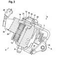
- FIG. 3 shows cross section through the hydraulic unit 5 before.
- the pressure accumulator 13 connected to the medium-pressure chamber 12 is also shown with the compensating piston 14, which is acted on by spring force.
- the throttle opening 17 connecting the low-pressure chamber 16 with the medium-pressure chamber 12 is arranged such that it extends at a geodetically low point of the housing intermediate part 21 of the hydraulic unit 5 inclined to gravity g in and / or with the internal combustion engine. As explained above, this ensures that only bubble-free hydraulic fluid from the low-pressure chamber 16 is sucked into the medium-pressure space 12.
- each of the medium-pressure spaces 12 can also communicate with the associated low-pressure space 16 via two or more throttle openings 17. Conversely, it would also be conceivable to associate each of two medium-pressure chambers 12 with two or more low-pressure chambers 16 separated from one another.
- Gas bubbles which pass through the throttle opening 17 from the medium-pressure chamber 12 into the low-pressure chamber 16 during operation of the internal combustion engine, can be deposited into the interior of the cylinder head 2 via a vent opening 30 extending in the upper housing part 22 and opening into the cylinder head 2.
- the upper housing part 22 is coated with a sealing material made of elastomer material, not shown here.
- this coating is not limited only to the contact region to the intermediate housing part 21, but is located on the entire surface of the upper housing part 22 produced here in a deep-drawing of sheet steel.
- the volume designated by V L of the low-pressure chamber 16 on the one hand taking into account the space available in the cylinder head 2 and on the other hand, to be sized as large as possible with an always sufficient hydraulic fluid reservoir.
- V M the volume ratio
- V H the volume ratio (V L + V M ) to V H has a value of at least 2
- the pressure accumulator 13 the partition 18 and the check valve 15 limited volume of the medium-pressure space 12 and with V H the volume of the high-pressure chamber 11 delimited by the transmitter unit 6, by the slave unit or units 8 and by the hydraulic valve 10 is designated.
Landscapes
- Engineering & Computer Science (AREA)
- Mechanical Engineering (AREA)
- General Engineering & Computer Science (AREA)
- Valve Device For Special Equipments (AREA)
- Valve-Gear Or Valve Arrangements (AREA)
- Cylinder Crankcases Of Internal Combustion Engines (AREA)
Applications Claiming Priority (1)
| Application Number | Priority Date | Filing Date | Title |
|---|---|---|---|
| DE102007054376A DE102007054376A1 (de) | 2007-11-14 | 2007-11-14 | Hydraulikeinheit für einen Zylinderkopf einer Brennkraftmaschine mit hydraulisch variablem Ventiltrieb |
Publications (3)
| Publication Number | Publication Date |
|---|---|
| EP2060754A2 true EP2060754A2 (fr) | 2009-05-20 |
| EP2060754A3 EP2060754A3 (fr) | 2010-05-05 |
| EP2060754B1 EP2060754B1 (fr) | 2011-12-14 |
Family
ID=40345032
Family Applications (1)
| Application Number | Title | Priority Date | Filing Date |
|---|---|---|---|
| EP08167285A Active EP2060754B1 (fr) | 2007-11-14 | 2008-10-22 | Unité hydraulique pour culasse d'un moteur à combustion interne dotée d'une commande de soupape hydraulique variable |
Country Status (6)
| Country | Link |
|---|---|
| US (1) | US8020526B2 (fr) |
| EP (1) | EP2060754B1 (fr) |
| JP (1) | JP5354260B2 (fr) |
| KR (1) | KR101515636B1 (fr) |
| CN (1) | CN101435353B (fr) |
| DE (1) | DE102007054376A1 (fr) |
Cited By (11)
| Publication number | Priority date | Publication date | Assignee | Title |
|---|---|---|---|---|
| EP2226477A1 (fr) * | 2009-03-05 | 2010-09-08 | Schaeffler Technologies AG & Co. KG | Unité hydraulique pour culasse de moteur à combustion interne dotée d'une commande hydraulique variable de soupape |
| EP2226476A1 (fr) | 2009-03-05 | 2010-09-08 | Schaeffler Technologies AG & Co. KG | Unité hydraulique pour culasse de moteur à combustion interne dotée d'une commande hydraulique variable de soupape |
| EP2282022A1 (fr) * | 2009-06-30 | 2011-02-09 | C.R.F. Società Consortile per Azioni | Système hydraulique à contrôle électronique pour la commande variable de soupapes d'un moteur à combustion interne, avec remplissage rapide de partie haute pression du système |
| WO2011069836A1 (fr) * | 2009-12-08 | 2011-06-16 | Schaeffler Technologies Gmbh & Co. Kg | Moteur à combustion interne équipé d'une commande de soupape électro-hydraulique et procédé pour le fonctionnement du moteur à combustion interne |
| WO2011124500A1 (fr) * | 2010-04-06 | 2011-10-13 | Schaeffler Technologies Gmbh & Co. Kg | Moteur à combustion interne avec deux espaces de lubrification séparés l'un de l'autre de manière étanche aux fluides |
| DE102010024028A1 (de) | 2010-06-16 | 2011-12-22 | Schaeffler Technologies Gmbh & Co. Kg | Hydraulikeinheit für einen Zylinderkopf einer Brennkraftmaschine mit hydraulisch variablem Gaswechselventiltrieb |
| WO2012069211A1 (fr) * | 2010-11-25 | 2012-05-31 | Schaeffler Technologies AG & Co. KG | Accumulateur de pression d'un système d'actionnement hydraulique |
| DE102012200469A1 (de) * | 2012-01-13 | 2013-07-18 | Schaeffler Technologies AG & Co. KG | Aktuator für vollvariable Ventiltriebsysteme |
| DE102016218918A1 (de) | 2016-09-29 | 2018-03-29 | Schaeffler Technologies AG & Co. KG | Brennkraftmaschine mit hydraulisch variablem Gaswechselventiltrieb |
| DE102016219297A1 (de) | 2016-10-05 | 2018-04-05 | Schaeffler Technologies AG & Co. KG | Hydraulikeinheit für eine Brennkraftmaschine mit hydraulisch variablem Gaswechselventiltrieb |
| CN111164277A (zh) * | 2017-10-02 | 2020-05-15 | V·拉比 | 再生阀液压致动器 |
Families Citing this family (16)
| Publication number | Priority date | Publication date | Assignee | Title |
|---|---|---|---|---|
| EP2261471B1 (fr) * | 2009-05-25 | 2014-09-17 | C.R.F. Società Consortile per Azioni | Moteur à combustion interne avec deux soupapes d'admission hydrauliques avec des ressorts différents pour chaque cylindre |
| DE102010018209A1 (de) | 2010-04-26 | 2011-10-27 | Schaeffler Technologies Gmbh & Co. Kg | Hydraulikeinheit für einen Zylinderkopf einer Brennkraftmaschine mit hydraulisch variablem Gaswechselventiltrieb |
| CN102278161B (zh) * | 2011-07-19 | 2013-07-24 | 天津大学 | 可变气门用缓冲液压缸 |
| DE102012212860B3 (de) * | 2012-07-23 | 2013-12-12 | Schaeffler Technologies AG & Co. KG | Verfahren zur Ermittlung der Füllung der Zylinder von Hubkolbenbrennkraftmaschinen |
| DE102012221354A1 (de) | 2012-11-22 | 2013-01-24 | Schaeffler Technologies AG & Co. KG | Hydraulikeinheit für einen Zylinderkopf einer Brennkraftmaschine mit hydraulisch variablem Gaswechselventiltrieb |
| DE102013213695B4 (de) * | 2013-07-12 | 2024-11-14 | Schaeffler Technologies AG & Co. KG | Vorrichtung zum Entlüften von Hohlräumen |
| SE540359C2 (sv) * | 2013-10-16 | 2018-08-07 | Freevalve Ab | Förbränningsmotor |
| US9217339B2 (en) | 2014-04-24 | 2015-12-22 | Ford Global Technologies, Llc | Hydraulic rolling cylinder deactivation systems and methods |
| US9631526B2 (en) * | 2014-09-17 | 2017-04-25 | Fca Us Llc | Engine variable valve lift system having integrated hydraulic fluid retention |
| DE102014219736A1 (de) | 2014-09-30 | 2016-03-31 | Schaeffler Technologies AG & Co. KG | Ventiltrieb einer Brennkraftmaschine |
| DE102016218784A1 (de) * | 2015-10-26 | 2017-04-27 | Schaeffler Technologies AG & Co. KG | Ventilsteueraktor mit Eisenspansammelmagnet in Ölleitung |
| EP3418536B1 (fr) | 2016-03-31 | 2021-05-05 | Mazda Motor Corporation | Dispositif de commande de moteur multi-cylindre |
| JP6350975B2 (ja) * | 2016-03-31 | 2018-07-04 | マツダ株式会社 | エンジンの制御装置 |
| GB2553120B (en) * | 2016-08-24 | 2019-12-25 | Jaguar Land Rover Ltd | Variable valve lift system with a diffusing system |
| DE102018129287A1 (de) | 2018-11-21 | 2020-05-28 | Schaeffler Technologies AG & Co. KG | Verbrennungsmotor mit hydraulisch variablem Gaswechselventiltrieb |
| US11168592B2 (en) * | 2019-02-27 | 2021-11-09 | Ford Global Technologies, Llc | Variable valve actuation system |
Citations (1)
| Publication number | Priority date | Publication date | Assignee | Title |
|---|---|---|---|---|
| DE102006008676A1 (de) | 2006-02-24 | 2007-08-30 | Schaeffler Kg | Zylinderkopf einer Brennkraftmaschine mit elektrohydraulischer Ventilsteuerung |
Family Cites Families (9)
| Publication number | Priority date | Publication date | Assignee | Title |
|---|---|---|---|---|
| DE3604233A1 (de) * | 1986-02-11 | 1987-08-13 | Bosch Gmbh Robert | Ventilsteuervorrichtung fuer eine hubkolben-brennkraftmaschine |
| JPH02221610A (ja) * | 1989-02-22 | 1990-09-04 | Honda Motor Co Ltd | 内燃機関の動弁装置 |
| JP2934682B2 (ja) * | 1991-03-28 | 1999-08-16 | 本田技研工業株式会社 | 内燃機関用機関弁の油圧駆動装置 |
| DE4206696C2 (de) * | 1992-03-04 | 2000-12-14 | Bosch Gmbh Robert | Hydraulische Ventilsteuervorrichtung für Motorventile |
| EP1232336A4 (fr) * | 1999-09-17 | 2009-08-05 | Diesel Engine Retarders Inc | Accumulateur a volume captif pour systeme a perte de mouvement |
| ITTO20010269A1 (it) * | 2001-03-23 | 2002-09-23 | Fiat Ricerche | Motore a combustione interna, con sistema idraulico di azionamento variabile delle valvole, e mezzi di compensazione delle variazioni di vol |
| DE10161438B4 (de) * | 2001-12-14 | 2004-07-15 | Man B&W Diesel A/S | Hubkolbenmaschine |
| US6644265B2 (en) * | 2002-04-09 | 2003-11-11 | Eaton Corporation | Electro-hydraulic manifold assembly and method of making same for controlling de-activation of combustion chamber valves in a multicylinder engine |
| US7069887B2 (en) * | 2002-05-14 | 2006-07-04 | Caterpillar Inc. | Engine valve actuation system |
-
2007
- 2007-11-14 DE DE102007054376A patent/DE102007054376A1/de not_active Withdrawn
-
2008
- 2008-10-22 EP EP08167285A patent/EP2060754B1/fr active Active
- 2008-11-13 KR KR1020080112489A patent/KR101515636B1/ko active Active
- 2008-11-13 CN CN2008101733593A patent/CN101435353B/zh active Active
- 2008-11-14 JP JP2008291700A patent/JP5354260B2/ja not_active Expired - Fee Related
- 2008-11-14 US US12/271,031 patent/US8020526B2/en active Active
Patent Citations (1)
| Publication number | Priority date | Publication date | Assignee | Title |
|---|---|---|---|---|
| DE102006008676A1 (de) | 2006-02-24 | 2007-08-30 | Schaeffler Kg | Zylinderkopf einer Brennkraftmaschine mit elektrohydraulischer Ventilsteuerung |
Cited By (25)
| Publication number | Priority date | Publication date | Assignee | Title |
|---|---|---|---|---|
| EP2226477A1 (fr) * | 2009-03-05 | 2010-09-08 | Schaeffler Technologies AG & Co. KG | Unité hydraulique pour culasse de moteur à combustion interne dotée d'une commande hydraulique variable de soupape |
| EP2226476A1 (fr) | 2009-03-05 | 2010-09-08 | Schaeffler Technologies AG & Co. KG | Unité hydraulique pour culasse de moteur à combustion interne dotée d'une commande hydraulique variable de soupape |
| US8215271B2 (en) | 2009-03-05 | 2012-07-10 | Schaeffler Technologies AG & Co. KG | Hydraulic unit for a cylinder head of an internal combustion engine with hydraulically variable gas-exchange valve train |
| US8210140B2 (en) | 2009-03-05 | 2012-07-03 | Schaeffler Technologies AG & Co. KG | Hydraulic unit for a cylinder head of an internal combustion engine with hydraulically variable gas-exchange valve train |
| US8230830B2 (en) | 2009-06-30 | 2012-07-31 | C.R.F. Società Consortile Per Azioni | Electronically controlled hydraulic system for variable actuation of the valves of an internal combustion engine, with fast filling of the high pressure side of the system |
| EP2282022A1 (fr) * | 2009-06-30 | 2011-02-09 | C.R.F. Società Consortile per Azioni | Système hydraulique à contrôle électronique pour la commande variable de soupapes d'un moteur à combustion interne, avec remplissage rapide de partie haute pression du système |
| WO2011069836A1 (fr) * | 2009-12-08 | 2011-06-16 | Schaeffler Technologies Gmbh & Co. Kg | Moteur à combustion interne équipé d'une commande de soupape électro-hydraulique et procédé pour le fonctionnement du moteur à combustion interne |
| US9212573B2 (en) | 2009-12-08 | 2015-12-15 | Schaeffler Technologies AG & Co. KG | Internal combustion engine having electrohydraulic valve control and method for operating said internal combustion engine |
| WO2011124500A1 (fr) * | 2010-04-06 | 2011-10-13 | Schaeffler Technologies Gmbh & Co. Kg | Moteur à combustion interne avec deux espaces de lubrification séparés l'un de l'autre de manière étanche aux fluides |
| CN102844530A (zh) * | 2010-04-06 | 2012-12-26 | 谢夫勒科技股份两合公司 | 带有两个液密地相互分隔的润滑空间的内燃机 |
| CN102844530B (zh) * | 2010-04-06 | 2016-01-13 | 舍弗勒技术股份两合公司 | 带有两个液密地相互分隔的润滑空间的内燃机 |
| US8863715B2 (en) | 2010-04-06 | 2014-10-21 | Schaeffler Technologies Gmbh & Co. Kg | Internal combustion engine having two lubricating chambers separated from one another in a fluid-tight manner |
| DE102010024028A1 (de) | 2010-06-16 | 2011-12-22 | Schaeffler Technologies Gmbh & Co. Kg | Hydraulikeinheit für einen Zylinderkopf einer Brennkraftmaschine mit hydraulisch variablem Gaswechselventiltrieb |
| WO2012069211A1 (fr) * | 2010-11-25 | 2012-05-31 | Schaeffler Technologies AG & Co. KG | Accumulateur de pression d'un système d'actionnement hydraulique |
| DE102012200469A1 (de) * | 2012-01-13 | 2013-07-18 | Schaeffler Technologies AG & Co. KG | Aktuator für vollvariable Ventiltriebsysteme |
| DE102016218918A1 (de) | 2016-09-29 | 2018-03-29 | Schaeffler Technologies AG & Co. KG | Brennkraftmaschine mit hydraulisch variablem Gaswechselventiltrieb |
| WO2018059627A1 (fr) | 2016-09-29 | 2018-04-05 | Schaeffler Technologies AG & Co. KG | Moteur à combustion interne à mécanisme de distribution hydrauliquement variable de soupape d'échange des gaz |
| DE102016218918B4 (de) | 2016-09-29 | 2018-09-13 | Schaeffler Technologies AG & Co. KG | Brennkraftmaschine mit hydraulisch variablem Gaswechselventiltrieb |
| US10900389B2 (en) | 2016-09-29 | 2021-01-26 | Schaeffler Technologies AG & Co. KG | Internal combustion engine with a hydraulically variable gas exchange valve train |
| DE102016219297A1 (de) | 2016-10-05 | 2018-04-05 | Schaeffler Technologies AG & Co. KG | Hydraulikeinheit für eine Brennkraftmaschine mit hydraulisch variablem Gaswechselventiltrieb |
| WO2018065010A1 (fr) | 2016-10-05 | 2018-04-12 | Schaeffler Technologies AG & Co. KG | Unité hydraulique pour un moteur à combustion interne à commande hydraulique variable des soupapes d'échange des gaz |
| US11187117B2 (en) | 2016-10-05 | 2021-11-30 | Schaeffler Technologies AG & Co. KG | Hydraulics unit for an internal combustion engine with hydraulically variable gas exchange valve gear |
| DE102016219297B4 (de) | 2016-10-05 | 2021-12-30 | Schaeffler Technologies AG & Co. KG | Hydraulikeinheit für eine Brennkraftmaschine mit hydraulisch variablem Gaswechselventiltrieb |
| CN111164277A (zh) * | 2017-10-02 | 2020-05-15 | V·拉比 | 再生阀液压致动器 |
| CN111164277B (zh) * | 2017-10-02 | 2021-12-14 | V·拉比 | 再生阀液压致动器 |
Also Published As
| Publication number | Publication date |
|---|---|
| CN101435353B (zh) | 2013-03-27 |
| CN101435353A (zh) | 2009-05-20 |
| DE102007054376A1 (de) | 2009-05-20 |
| US8020526B2 (en) | 2011-09-20 |
| US20090120389A1 (en) | 2009-05-14 |
| EP2060754B1 (fr) | 2011-12-14 |
| KR20090049999A (ko) | 2009-05-19 |
| KR101515636B1 (ko) | 2015-04-27 |
| JP5354260B2 (ja) | 2013-11-27 |
| JP2009121481A (ja) | 2009-06-04 |
| EP2060754A3 (fr) | 2010-05-05 |
Similar Documents
| Publication | Publication Date | Title |
|---|---|---|
| EP2060754B1 (fr) | Unité hydraulique pour culasse d'un moteur à combustion interne dotée d'une commande de soupape hydraulique variable | |
| EP2226477B1 (fr) | Unité hydraulique pour culasse de moteur à combustion interne dotée d'une commande hydraulique variable de soupape | |
| EP0736672B1 (fr) | Procédé de freinage moteur pour moteur à combustion interne à quatre temps | |
| DE102008045741B4 (de) | Geräuscharme Kraftstoffeinspritzpumpe | |
| EP0694693B1 (fr) | Méthode et dispositif pour la commande d'une soupape | |
| DD146076A1 (de) | Hydraulische einrichtung zum betaetigen von gaswechselventilen | |
| DE4122827A1 (de) | Ventilsystem fuer einen kraftfahrzeugmotor | |
| DE102022201575A1 (de) | Hydraulikblock für ein Hydraulikaggregat einer hydraulischen Fremdkraftbremsanlage | |
| DE3939065A1 (de) | Hydraulische ventilsteuervorrichtung fuer brennkraftmaschinen | |
| DE102009035404A1 (de) | Verbrennungsmotor mit elektrohydraulisch hubvariabler Ventilbetätigung | |
| DE102011051487B4 (de) | Elektrohydraulische Ventilsteuerung | |
| EP2381075B1 (fr) | Unité hydraulique pour une tête de cylindre d'un moteur à combustion interne dotée d'une commande de soupape hydraulique variable à échange de gaz | |
| EP0584575A1 (fr) | Moteur à combustion interne ayant un mécanisme pour changer les modes opératoires. | |
| EP0455763B1 (fr) | Dispositif de commande hydraulique de soupapes pour un moteur a combustion interne multicylindre | |
| DE19706769B4 (de) | Ventilsteuervorrichtung für eine Brennkraftmaschine | |
| EP2226476B1 (fr) | Unité hydraulique pour culasse de moteur à combustion interne dotée d'une commande hydraulique variable de soupape | |
| DE102010060960A1 (de) | Elektrohydraulik-Variabler-Ventilhub-Vorrichtung | |
| DE102016204329B4 (de) | Hydraulischer Ventiltrieb für eine Brennkraftmaschine | |
| DE102016218562B4 (de) | Elektrohydraulischer Ventiltrieb zur variablen Öffnungsbetätigung von zwei Gaswechselventilen eines Zylinders eines Verbrennungsmotors | |
| DE4244374C2 (de) | Ventilsteuervorrichtung | |
| DE102007038530A1 (de) | Kraftstoffhochdruckpumpe | |
| EP1022444B1 (fr) | Commande de soupape à régulation hydraulique pour culasse multisoupapes | |
| EP1509685B1 (fr) | Mecanisme de distribution variable a actionnement hydraulique d'un moteur a combustion interne | |
| DE3437834A1 (de) | Mehrwegeventil, insbesondere fremdkraftgesteuertes bremsventil | |
| DE4039075A1 (de) | Ventiltrieb fuer zumindest zwei gleichzeitig betaetigbare hubventile |
Legal Events
| Date | Code | Title | Description |
|---|---|---|---|
| PUAI | Public reference made under article 153(3) epc to a published international application that has entered the european phase |
Free format text: ORIGINAL CODE: 0009012 |
|
| 17P | Request for examination filed |
Effective date: 20081022 |
|
| AK | Designated contracting states |
Kind code of ref document: A2 Designated state(s): AT BE BG CH CY CZ DE DK EE ES FI FR GB GR HR HU IE IS IT LI LT LU LV MC MT NL NO PL PT RO SE SI SK TR |
|
| AX | Request for extension of the european patent |
Extension state: AL BA MK RS |
|
| PUAL | Search report despatched |
Free format text: ORIGINAL CODE: 0009013 |
|
| AK | Designated contracting states |
Kind code of ref document: A3 Designated state(s): AT BE BG CH CY CZ DE DK EE ES FI FR GB GR HR HU IE IS IT LI LT LU LV MC MT NL NO PL PT RO SE SI SK TR |
|
| AX | Request for extension of the european patent |
Extension state: AL BA MK RS |
|
| AKX | Designation fees paid |
Designated state(s): DE FR GB IT SE |
|
| GRAP | Despatch of communication of intention to grant a patent |
Free format text: ORIGINAL CODE: EPIDOSNIGR1 |
|
| RIC1 | Information provided on ipc code assigned before grant |
Ipc: F01L 9/02 20060101AFI20110328BHEP |
|
| GRAS | Grant fee paid |
Free format text: ORIGINAL CODE: EPIDOSNIGR3 |
|
| RAP1 | Party data changed (applicant data changed or rights of an application transferred) |
Owner name: SCHAEFFLER TECHNOLOGIES GMBH & CO. KG |
|
| GRAA | (expected) grant |
Free format text: ORIGINAL CODE: 0009210 |
|
| AK | Designated contracting states |
Kind code of ref document: B1 Designated state(s): DE FR GB IT SE |
|
| REG | Reference to a national code |
Ref country code: GB Ref legal event code: FG4D Free format text: NOT ENGLISH |
|
| REG | Reference to a national code |
Ref country code: DE Ref legal event code: R096 Ref document number: 502008005840 Country of ref document: DE Effective date: 20120209 |
|
| REG | Reference to a national code |
Ref country code: SE Ref legal event code: TRGR |
|
| RAP2 | Party data changed (patent owner data changed or rights of a patent transferred) |
Owner name: SCHAEFFLER TECHNOLOGIES AG & CO. KG |
|
| REG | Reference to a national code |
Ref country code: DE Ref legal event code: R081 Ref document number: 502008005840 Country of ref document: DE Owner name: SCHAEFFLER TECHNOLOGIES AG & CO. KG, DE Free format text: FORMER OWNER: SCHAEFFLER TECHNOLOGIES GMBH & CO. KG, 91074 HERZOGENAURACH, DE Effective date: 20120828 Ref country code: DE Ref legal event code: R081 Ref document number: 502008005840 Country of ref document: DE Owner name: SCHAEFFLER TECHNOLOGIES GMBH & CO. KG, DE Free format text: FORMER OWNER: SCHAEFFLER TECHNOLOGIES GMBH & CO. KG, 91074 HERZOGENAURACH, DE Effective date: 20120828 |
|
| PLBE | No opposition filed within time limit |
Free format text: ORIGINAL CODE: 0009261 |
|
| STAA | Information on the status of an ep patent application or granted ep patent |
Free format text: STATUS: NO OPPOSITION FILED WITHIN TIME LIMIT |
|
| 26N | No opposition filed |
Effective date: 20120917 |
|
| REG | Reference to a national code |
Ref country code: DE Ref legal event code: R097 Ref document number: 502008005840 Country of ref document: DE Effective date: 20120917 |
|
| REG | Reference to a national code |
Ref country code: DE Ref legal event code: R081 Ref document number: 502008005840 Country of ref document: DE Owner name: SCHAEFFLER TECHNOLOGIES AG & CO. KG, DE Free format text: FORMER OWNER: SCHAEFFLER TECHNOLOGIES AG & CO. KG, 91074 HERZOGENAURACH, DE Effective date: 20140214 Ref country code: DE Ref legal event code: R081 Ref document number: 502008005840 Country of ref document: DE Owner name: SCHAEFFLER TECHNOLOGIES GMBH & CO. KG, DE Free format text: FORMER OWNER: SCHAEFFLER TECHNOLOGIES AG & CO. KG, 91074 HERZOGENAURACH, DE Effective date: 20140214 |
|
| REG | Reference to a national code |
Ref country code: DE Ref legal event code: R081 Ref document number: 502008005840 Country of ref document: DE Owner name: SCHAEFFLER TECHNOLOGIES AG & CO. KG, DE Free format text: FORMER OWNER: SCHAEFFLER TECHNOLOGIES GMBH & CO. KG, 91074 HERZOGENAURACH, DE Effective date: 20150401 |
|
| REG | Reference to a national code |
Ref country code: FR Ref legal event code: PLFP Year of fee payment: 8 |
|
| REG | Reference to a national code |
Ref country code: FR Ref legal event code: PLFP Year of fee payment: 9 |
|
| REG | Reference to a national code |
Ref country code: FR Ref legal event code: PLFP Year of fee payment: 10 |
|
| REG | Reference to a national code |
Ref country code: FR Ref legal event code: PLFP Year of fee payment: 11 |
|
| REG | Reference to a national code |
Ref country code: DE Ref legal event code: R079 Ref document number: 502008005840 Country of ref document: DE Free format text: PREVIOUS MAIN CLASS: F01L0009020000 Ipc: F01L0009100000 |
|
| P01 | Opt-out of the competence of the unified patent court (upc) registered |
Effective date: 20230522 |
|
| PGFP | Annual fee paid to national office [announced via postgrant information from national office to epo] |
Ref country code: DE Payment date: 20251211 Year of fee payment: 18 |
|
| PGFP | Annual fee paid to national office [announced via postgrant information from national office to epo] |
Ref country code: GB Payment date: 20251022 Year of fee payment: 18 |
|
| PGFP | Annual fee paid to national office [announced via postgrant information from national office to epo] |
Ref country code: IT Payment date: 20251024 Year of fee payment: 18 |
|
| PGFP | Annual fee paid to national office [announced via postgrant information from national office to epo] |
Ref country code: FR Payment date: 20251029 Year of fee payment: 18 |
|
| PGFP | Annual fee paid to national office [announced via postgrant information from national office to epo] |
Ref country code: SE Payment date: 20251021 Year of fee payment: 18 |