EP2060775A2 - Lance de carburant et ensemble - Google Patents
Lance de carburant et ensemble Download PDFInfo
- Publication number
- EP2060775A2 EP2060775A2 EP08168775A EP08168775A EP2060775A2 EP 2060775 A2 EP2060775 A2 EP 2060775A2 EP 08168775 A EP08168775 A EP 08168775A EP 08168775 A EP08168775 A EP 08168775A EP 2060775 A2 EP2060775 A2 EP 2060775A2
- Authority
- EP
- European Patent Office
- Prior art keywords
- fuel
- inlet adapter
- fuel lance
- lance
- cylinder head
- Prior art date
- Legal status (The legal status is an assumption and is not a legal conclusion. Google has not performed a legal analysis and makes no representation as to the accuracy of the status listed.)
- Granted
Links
- 239000000446 fuel Substances 0.000 title claims abstract description 332
- 239000012530 fluid Substances 0.000 claims description 24
- 239000004033 plastic Substances 0.000 claims description 5
- 229920003023 plastic Polymers 0.000 claims description 5
- 238000007789 sealing Methods 0.000 claims description 5
- 239000000463 material Substances 0.000 claims description 4
- 230000008901 benefit Effects 0.000 description 10
- 238000004519 manufacturing process Methods 0.000 description 10
- 238000000605 extraction Methods 0.000 description 6
- 238000002347 injection Methods 0.000 description 5
- 239000007924 injection Substances 0.000 description 5
- 238000004891 communication Methods 0.000 description 4
- 230000009286 beneficial effect Effects 0.000 description 3
- 238000013461 design Methods 0.000 description 3
- 239000013618 particulate matter Substances 0.000 description 3
- 238000012546 transfer Methods 0.000 description 3
- 238000002485 combustion reaction Methods 0.000 description 2
- 238000011109 contamination Methods 0.000 description 2
- 238000003754 machining Methods 0.000 description 2
- 239000002245 particle Substances 0.000 description 2
- 230000000717 retained effect Effects 0.000 description 2
- 229910000831 Steel Inorganic materials 0.000 description 1
- 230000000712 assembly Effects 0.000 description 1
- 238000000429 assembly Methods 0.000 description 1
- 230000015572 biosynthetic process Effects 0.000 description 1
- 230000001419 dependent effect Effects 0.000 description 1
- 238000003780 insertion Methods 0.000 description 1
- 230000037431 insertion Effects 0.000 description 1
- 238000009434 installation Methods 0.000 description 1
- 239000002184 metal Substances 0.000 description 1
- 238000012986 modification Methods 0.000 description 1
- 230000004048 modification Effects 0.000 description 1
- 238000012856 packing Methods 0.000 description 1
- 239000010959 steel Substances 0.000 description 1
Images


Classifications
-
- F—MECHANICAL ENGINEERING; LIGHTING; HEATING; WEAPONS; BLASTING
- F02—COMBUSTION ENGINES; HOT-GAS OR COMBUSTION-PRODUCT ENGINE PLANTS
- F02M—SUPPLYING COMBUSTION ENGINES IN GENERAL WITH COMBUSTIBLE MIXTURES OR CONSTITUENTS THEREOF
- F02M55/00—Fuel-injection apparatus characterised by their fuel conduits or their venting means; Arrangements of conduits between fuel tank and pump F02M37/00
- F02M55/004—Joints; Sealings
- F02M55/005—Joints; Sealings for high pressure conduits, e.g. connected to pump outlet or to injector inlet
-
- F—MECHANICAL ENGINEERING; LIGHTING; HEATING; WEAPONS; BLASTING
- F02—COMBUSTION ENGINES; HOT-GAS OR COMBUSTION-PRODUCT ENGINE PLANTS
- F02M—SUPPLYING COMBUSTION ENGINES IN GENERAL WITH COMBUSTIBLE MIXTURES OR CONSTITUENTS THEREOF
- F02M55/00—Fuel-injection apparatus characterised by their fuel conduits or their venting means; Arrangements of conduits between fuel tank and pump F02M37/00
- F02M55/02—Conduits between injection pumps and injectors, e.g. conduits between pump and common-rail or conduits between common-rail and injectors
-
- F—MECHANICAL ENGINEERING; LIGHTING; HEATING; WEAPONS; BLASTING
- F02—COMBUSTION ENGINES; HOT-GAS OR COMBUSTION-PRODUCT ENGINE PLANTS
- F02M—SUPPLYING COMBUSTION ENGINES IN GENERAL WITH COMBUSTIBLE MIXTURES OR CONSTITUENTS THEREOF
- F02M61/00—Fuel-injectors not provided for in groups F02M39/00 - F02M57/00 or F02M67/00
- F02M61/14—Arrangements of injectors with respect to engines; Mounting of injectors
-
- F—MECHANICAL ENGINEERING; LIGHTING; HEATING; WEAPONS; BLASTING
- F02—COMBUSTION ENGINES; HOT-GAS OR COMBUSTION-PRODUCT ENGINE PLANTS
- F02M—SUPPLYING COMBUSTION ENGINES IN GENERAL WITH COMBUSTIBLE MIXTURES OR CONSTITUENTS THEREOF
- F02M61/00—Fuel-injectors not provided for in groups F02M39/00 - F02M57/00 or F02M67/00
- F02M61/16—Details not provided for in, or of interest apart from, the apparatus of groups F02M61/02 - F02M61/14
- F02M61/165—Filtering elements specially adapted in fuel inlets to injector
Definitions
- This invention relates to a connector for use in connecting a supply of fuel under high pressure to a fuel injector.
- the invention relates to a fuel lance for use in an arrangement of the type in which an injector is located within a bore provided in an engine cylinder head, the fuel being supplied through the cylinder head to the injector.
- a fuel pump In an internal combustion engine, it is known for a fuel pump to supply fuel at high-pressure for delivery to each cylinder of the engine by means of a dedicated fuel injector.
- the fuel injector is received within a bore provided in a cylinder head of the cylinder, and a connector (or fuel lance) is used to provide a fluid connection between the fuel injector and a fuel supply line (or pipe) from a fuel pump or accumulator volume / common rail.
- a connector 1 is disposed within a transverse bore 3 in a cylinder head 5 that intersects with a bore 7 in which the injection nozzle 9 is housed.
- the connector 1 has a spherical taper 11 on its outlet end to form a fluid tight seal against a lateral seating face 13 on the injection nozzle 9 when it is clamped in place by means of a retaining screw 15.
- the retaining screw 15 has an external screw thread that cooperates with an internal screw thread provided in the transverse bore 3 of the cylinder head 5.
- a spherical shoulder 17 is also provided on the connector 1, against which the retaining screw 15 presses when tightened.
- the inlet end section 19 of connector 1 projects beyond the retaining screw 15 and the cylinder head 5 in order that the fuel pipe 21 may be clamped in place.
- the inlet end section 19 is provided with an external thread 23 onto which a female pipe nut 25 is screwed to clamp the fuel pipe 21 to the end of the connector 1.
- the inlet end section 19 of the connector 1 is further provided with a female conical seating surface 27 about the fuel passage 29 that passes through the connector 1, against which a male conical seating surface 31 of the fuel pipe 21 seals when the pipe nut 25 is tightened.
- the prior art fuel supply line arrangements for connecting a fuel pipe to an injection nozzle have a number of disadvantages.
- the shoulder (or flange) on the connector that is required to transfer the load from the retaining screw to the conical (or spherical) sealing face at the injector end of the connector adds to the complexity of manufacture and prohibits the use of a smaller diameter connector, which would reduce the cost of manufacture.
- the prior art connectors are typically considerably longer than the length of the bore of the cylinder head in which they are located. Therefore, the connector extends beyond the cylinder head and takes up a significant amount of space within the engine, which can cause packing conflicts with other components fixed in the region of the cylinders. The length of such prior art connectors also adds to the cost of manufacturing this component.
- a fuel connector / lance that provides design and manufacturing cost benefits and/or which achieves installation benefits over the prior art.
- a further issue with some prior art fuel supply line arrangements is that a tight seal between the connector and the injection nozzle requires the tightening of a retaining screw into the cylinder head and the transfer of the load from the screw through the connector. This mechanism thus requires the rotation of tightly fitting parts and the friction between the rotating components can lead to the generation of undesirable particles (debris), which could lead to the contamination of fuel and/or the wearing of the components.
- an anti-rotation device may be necessary on the connector to prevent it rotating within the cylinder head, further adding to design complexity and manufacturing costs. It would be further desirable to provide a fuel supply line arrangement that reduces or eliminates the requirement for the rotation of components within the cylinder head during assembly and/or disassembly.
- the invention relates to a fuel connector or lance that overcomes or at least alleviates at least one of the above-mentioned problems and disadvantages in the prior art, and also to fuel supply line arrangements comprising such a fuel connector or lance.
- the invention provides a fuel lance, a fuel lance assembly, and a fuel supply line arrangement that provides all necessary functionality and which provides desirable advantages over the prior art, such as greater simplicity and, therefore, a lower cost of manufacture. It may also avoid prior art design limitations on the size of various parts, such that it takes up less space within the increasingly complex and crowded engine space.
- the apparatus of the invention provides functional benefits in terms of reducing component wear and avoiding potential fuel contamination from worn engine components.
- the invention provides a fuel lance assembly for an engine comprising a fuel injector to be located within a bore of an engine cylinder head, the fuel lance assembly comprising: a fuel lance to be received in a passage provided in the cylinder head and a connection arrangement comprising an inlet adapter for securing the fuel lance within the passage.
- the fuel lance comprises a tubular member of constant external diameter and arranged to be received, in use, within the passage and has a first end (or distal end) being shaped for cooperation with a seating surface of the fuel injector, and a second end (or proximal end) being shaped for cooperation with the connection arrangement, and a bore therethrough to define a fuel flow path between the first end and the second end of the fuel lance.
- the inlet adapter is provided with an attachment system for engaging a compatible attachment system of the cylinder head and has a proximal region for receiving a high pressure fuel pipe.
- the inlet adapter further has a distal region provided with an opening (e.g. in the form of a bore) being adapted to receive the second end of the fuel lance.
- the length of the fuel lance is shorter than the length of the passage of the cylinder head such that, in use, the fuel lance can be fully received within the passage.
- the second end of the fuel lance does not protrude from the cylinder head when the lance is secured within the passage of the cylinder head.
- the inlet adapter is arranged to be at least in part received within the passage of the cylinder head (for example, at least the distal region thereof is beneficially received within the passage).
- the inlet adapter clamps the first end of the fuel lance to the seating surface of the fuel injector such that a substantially fluid tight seal is formed between the fuel lance and the fuel injector.
- the inlet adapter may be arranged to be fully received within the passage of the cylinder head, such that the proximal region thereof does not protrude from the cylinder head.
- the fuel lance is provided with an external circumferential groove (i.e. on the outer surface of the fuel lance) to receive a thrust clip for engagement with a surface of the inlet adapter, such that when the lance is secured within the passage of the cylinder head by the inlet adapter, the surface of the inlet adapter exerts an axial load through the thrust clip and along the length of the fuel lance to provide a sealing pressure between the first end of the fuel lance and the seating surface of the fuel injector.
- an external circumferential groove i.e. on the outer surface of the fuel lance
- the inner wall defining the opening of the inlet adapter which is arranged to receive the second end of the fuel lance is provided with an annular groove, wherein the distal facing surface of the groove is shaped to provide a conical surface for engagement with the thrust clip of the fuel lance.
- the thrust clip is located such that it is also received within the opening of the inlet adapter.
- the opening of the inlet adapter may have a stepped internal diameter, wherein the internal diameter of the opening distal to the annular groove (i.e. between the annular groove and the aperture of the opening) is of greater diameter than the internal diameter of the opening proximal to the groove.
- stepped it will be understood that the internal diameter changes between a first and second location within the opening, and this change may conveniently be brought about by way of a step. However, a gradual change in the internal diameter of the opening (e.g. by way of a slope in the wall of the opening) may also be employed.
- the fuel lance and inlet adapter may conveniently be arranged such that, in use (e.g. during assembly of the fuel supply line arrangement), the thrust clip of the fuel lance may be located in the annular groove of the inlet adapter, and wherein on disengaging the inlet adapter from the cylinder head (with the fuel lance also in place), the second end of the fuel lance is releasably retained in the opening.
- This arrangement provides the further benefit that the fuel supply line arrangement can be readily disassembled, suitably avoiding the need to extract separately the fuel lance from within the passage of the cylinder head.
- the distal region of the inlet adapter is adapted to receive an extraction clip, in use, for releasably retaining the second end of the fuel lance in the opening (by engagement with a thrust clip or like feature provided on the fuel lance) when the inlet adapter is disengaged and/or removed from the cylinder head.
- the inlet adapter and/or the fuel lance may be provided with an annular seal member arranged to form a substantially fluid tight seal between the inlet adapter and/or the fuel lance, respectively, and the wall of the cylinder head defining the passage.
- the fuel lance assembly of the invention is arranged to provide a path of fluid communication between a high pressure fuel pipe and a fuel injector.
- the fuel lance assembly and, in particular, the fuel lance and/or the inlet adapter are arranged to engage a fuel pipe.
- the fuel lance assembly suitably further comprises a pipe nut for receiving a fuel pipe and arranged, in use, to engage the proximal region of the inlet adapter, such that a fuel flow path is established between the passage of the fuel pipe and the bore of the fuel lance.
- the pipe nut and inlet adapted are arranged to engage in such a way that the end of the fuel pipe directly cooperates with the second end of the fuel lance.
- the end of the fuel pipe indirectly communicates with the fuel lance, for example, the end of the fuel pipe may cooperate with a seating surface of the inlet adapter and the inlet adapter is arranged such that the fuel pipe fluidly communicates with the bore of the fuel lance.
- the proximal end of the inlet adapter is provided with a bore arranged to receive at least a portion of the pipe nut and having an internal (or female) screw-thread over at least part of the length of the bore, and wherein the pipe nut is provided with an external (or male) screw-thread over at least a portion of its outer surface, in use, for engagement with the internal screw-thread of the inlet adapter.
- the pipe nut is provided with a bore arranged to receive at least a length of the proximal region of the inlet adapter, at least a length of the bore being provided with a screw-thread (internal), in use, to cooperate with a screw-thread (external) provided over at least a part of the outer surface of the proximal region of the inlet adapter.
- engagement of the pipe nut with the inlet adapter suitably creates a compressive force between the head (or end) of the fuel pipe and the second end of the fuel lance, or a seating surface of the proximal region of the inlet adapter, respectively, to create a substantially fluid tight seal between the fuel pipe and the fuel lance or inlet adapter.
- the pipe nut is provided with a thrust surface to exert an axial load onto the end of the fuel pipe in order to compress the end of the fuel pipe against the cooperating surface of the fuel lance or inlet adapter.
- the first (or distal) end of the lance is provided with a male frusto-conical or part-spherical surface for cooperation with a female frusto-conical or part-spherical seating surface of the fuel injector.
- the fuel lance is provided with a frusto-conical seating surface at the first end, while in other embodiments a part-spherical surface is advantageous to compensate for any slight manufacturing inaccuracies.
- the second (or proximal) end of the lance may be provided with a female frusto-conical or part-spherical surface to cooperate with a male frusto-conical end of the fuel pipe, such that engagement of the pipe nut with the inlet adapter creates a substantially fluid tight seal between the fuel pipe and the lance.
- a part-spherical surface is advantageously employed at the second end of the lance to compensate for any slight manufacturing inaccuracies that may be present.
- the second end of the fuel lance is of male frusto-conical or part-spherical form, which may not be directly compatible (engageable) with a male frusto-conical or part-spherical surface of a fuel pipe.
- the distal region of the inlet adapter may be provided with a female frusto-conical or part-spherical surface (at the proximal end of the opening of the inlet adapter) for cooperating with the male second end of the lance.
- the proximal region of the inlet adapter is provided with a female frusto-conical or part-spherical surface for cooperating with the male end of the fuel pipe.
- the inlet adapter may still be used to indirectly couple the fuel lance to the fuel pipe.
- the distal region of the inlet adapter may be provided with a male frusto-conical or part-spherical surface (at the proximal end of the opening of the inlet adapter) for cooperating with the female second end of the fuel lance; and the proximal region of the inlet adapter may be provided with a female frusto-conical or part-spherical surface for cooperating with the male end of the fuel pipe.
- the inlet adapter is connected to the cylinder head by means of a screw-threaded engagement.
- a male screw-thread over at least a portion of the outer surface of the inlet adapter, and a female screw-thread over at least a length of the inner surface of the passage through the cylinder head.
- the male screw-thread on the external surface of the inlet adapter is provided over at least a portion of the proximal region of the inlet adapter.
- the inlet adapter is advantageously connectable to the cylinder head by means of a fixing member.
- the fixing member comprises at least one bolt or screw which is located between the inlet adapter and the cylinder head.
- the inlet adapter is conveniently provided with a radially extending circumferential flange, the flange having at least one axial through-bore extending from the proximal side to the distal side of the flange.
- Each of the at least one through-bore is adapted to receive a fixing member, such as a bolt or screw.
- the cylinder head is thus also provided with at least one fixing member hole (e.g.
- the inlet adapter is provided with a flange having two through-bores for mounting to the cylinder head using two fixing members, such as bolts.
- the inlet adapter when the inlet adapter is correctly assembled in a fuel lance assembly of the invention and, for example, received within the passage of the cylinder head, the distal side of the flange is axially spaced from the opposing surface of the cylinder head.
- the axial load between the at least one fixing member and the flange of the inlet adapter is transmitted from the inlet adapter to the lance (rather than to the cylinder head), to provide a sealing pressure between the first end of the fuel lance and the seating surface of the fuel injector.
- the fuel lance is formed from a plastics material. It may be advantageous for the frusto-conical or part-spherical surfaces at the first and second ends of the fuel lance to be heat-treated to provide a hard surface to minimise plastic deformation. In other embodiments it may be advantageous for the ends of the fuel lance to slightly deform on engagement with the fuel injector and inlet adapter, for example, to create a tighter seal against potential fuel leaks.
- the distal region of the inlet adapter may comprise an external guide to restrict angular movement within the passage of the cylinder head.
- the inlet adapter and/or the fuel lance may be provided with an integrated filter member (for example, an edge filter), arranged within the fuel flow path between the fuel injector and the fuel pipe to remove particulate matter.
- an integrated filter member for example, an edge filter
- the invention further relates to a fuel lance for use in supplying fuel to a fuel injector, the fuel lance comprising a tubular member arranged to be received, in use, within a passage provided in an engine cylinder head, the tubular member being shaped, at a first end thereof, for cooperation with a seating surface of the fuel injector and at a second end for cooperation with a connection arrangement comprising an inlet adapter, and having a bore to define a fluid flow path between the fuel injector and the connection arrangement; wherein the tubular member of the fuel lance has a constant external diameter.
- the fuel lance may be shorter than the passage of the cylinder head such that, in use, the fuel lance can be fully received within the passage.
- the second end of the fuel lance is arranged to be receivable within an opening (e.g. a bore) in the inlet adapter.
- the fuel lance is conveniently provided with a region of part-spherical form to permit a degree of articulation between the inlet adapter and the fuel lance at the interface of the cooperating surfaces. In this way, any inaccuracies in the machining of the inlet adapter and/or the fuel lance may be compensated by the tolerance in the cooperation between the respective seating surfaces.
- the fuel lance carries an annular seal member, for example, in the form of a resilient rubber ring, arranged to form a substantially fluid tight seal between the lance and the wall of the cylinder head defining the passage.
- the fuel lance may be provided with an external annular (circumferential) groove in which the seal member can be located.
- the fuel lance is provided with an external (outer) circumferential groove to receive a thrust clip for engagement with a surface of the inlet adapter, such that when the lance is secured within the passage of the cylinder head by the inlet adapter, the surface of the inlet adapter exerts an axial load through the thrust clip along the length on the lance to provide a sealing pressure between the first end of the lance and the seating surface of the fuel injector.
- the fuel lance may further comprise a filter member located within the bore of the fuel lance.
- the fuel lance may be provided with any or all of the features of the fuel lance described with regard to the first and second aspects of the invention.
- the invention provides a fuel supply line arrangement for an engine comprising a fuel injector to be located within a bore of an engine cylinder head; a fuel lance to be received in a passage provided in the cylinder head; a connection arrangement comprising an inlet adapter for securing the fuel lance within the passage; and a pipe nut for receiving a high pressure fuel pipe.
- the fuel lance in this second aspect of the invention may comprise any of the features described in relation to the first aspect of the invention or elsewhere herein.
- the connection arrangement and the inlet adapter in this second aspect of the invention may comprise any of the features described in relation to the first aspect of the invention and elsewhere herein.
- the pipe nut of the second aspect of the invention may comprise any of the features of the pipe nut described in relation to the first aspect of the invention and elsewhere herein.
- the invention also relates to an internal combustion engine having a fuel supply line arrangement or a fuel lance in accordance with the invention therein.
- the fuel lance and the fuel lance assemblies are arranged to be of such a length that the fuel lance and the inlet adapter when engaged with the fuel lance are fully received within the fuel lance passage of the cylinder head, such that none of the fuel lance assembly protrudes from the cylinder head into the engine space.
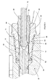
- a fuel lance 2 for use in connecting a supply of fuel from a high-pressure fuel pipe 70 to a fuel injector 20 is located within a passage 32 (which may be a bore) formed in a cylinder head 30.
- the injector 20 is housed within a bore 34 in the cylinder head, which intersects with the fuel supply passage 32 (approximately at 90°).
- the injector 20 is of the type which is provided with a seating surface 22 formed in a side thereof at approximately the height of intersection between the bore 34 and the passage 32, so that it is accessible from the passage 32, in use, so that fuel can be supplied from the fuel pipe 70 to the injector 20.
- the fuel lance 2 comprises a tubular member 4 of approximately constant external diameter and an axial bore 6 therethrough, which is suitable for the transfer of fuel at high pressure.
- the constant diameter of the fuel lance 2 provides an advantage that it can be readily manufactured from tubing, such as a thick-walled pressure tube.
- the fuel lance 2 has a first (distal) end 8 that is shaped for engagement with the seating surface 22 of the injector 20, and a second (proximal) end 10 that is shaped for cooperation with a connection arrangement 40.
- the fuel lance 2 has an overall length that is shorter than the length of the passage 32 in the cylinder head, so that it is entirely received within the cylinder head 30 and does not protrude into the engine space.
- the first end 8 of the fuel lance has a male frusto-conical or part-spherical seating surface to engage with a female frusto-conical seating surface 22 on the side of the injector 20.
- An annular seal member 16 in the form of a resilient rubber ring is located in an external circumferential groove in the lance 2. The seal member 16 cooperates with the internal wall of the passage 32 to form a substantially fluid tight seal between the fuel lance 2 and the passage 32 of the cylinder head 30.
- An inlet adapter 50 is located partially within an end of the passage 32, the inlet adapter 50 including a distal (or first) region 52 shaped for receiving the second end 10 of the fuel lance 2, and a proximal (or second) region 54 shaped for receiving the high-pressure fuel pipe 70.
- the distal region 52 of the inlet adapter 50 is provided with an opening 56 (which may be a bore having an aperture) within which the second end 10 of the lance 2 is located.
- annular groove 62 is formed in the (inner) wall of the opening 56 in the distal region 52 of the inlet adapter 50.
- the annular groove 62 is shaped such that on assembly of the fuel supply line arrangement, an axial load is passed from the inlet adapter 50 along the length of the lance 2 to the fuel injector 20; and on disassembly, the fuel lance 2 is releasably retained in the opening 56 of the inlet adapter 50, so that it can be conveniently removed from the passage 32.
- the fuel lance 2 is further provided with an external (outer) circumferential groove 12 in which is received a thrust clip 14 for engagement with a conical surface 58 which comprises the distal facing wall of the groove 62.
- the trust clip may be a sprung metal thrust clip of circular cross section.
- the thrust clip may take any suitable form.
- the opening 56 has a region of slightly increased internal diameter between the groove 62 and the distal end of the distal region 52, to enable the second end 10 of the lance 2, including the slightly protruding thrust clip 14, to be readily inserted into the opening 56.
- the region of the opening 56 proximal to the groove 62 has an internal diameter that more closely matches the outer circumference of the fuel lance 2 to restrict radial movement of the lance 2 within the inlet adapter 50.
- the proximal facing surface of the groove 62 acts as a lip (or hook) when the inlet adapter 50 is removed from the passage 32, to retain the thrust clip 14 of the fuel lance 2 within the groove 62.
- the aperture of the opening 56 it is convenient for the aperture of the opening 56 to be of smaller diameter than the external diameter of the thrust clip, but it is suitably not a tight fit with the external diameter of the fuel lance.
- the inlet adapter 50 includes an attachment system for engagement with an attachment system provided on the cylinder head 30.
- the attachment system is in the form of an externally screw-threaded region 92 provided on the inlet adapter 50, which is arranged to cooperate with screw threads formed in the end region of the passage 32 of the cylinder head 30.
- the second end 10 of the fuel lance 2 is provided with a female frusto-conical or part-spherical seating surface for engagement with a male frusto-conical end 74 of the fuel pipe 70.
- the proximal region 54 of the inlet adapter is provided with a bore 64, co-axial with the opening 56, into which the fuel pipe 70 and a pipe nut 80 are received.
- the pipe nut 80 is arranged to surround a portion of the fuel pipe 70 behind the end 74, and includes a thrust surface 84, in use, for exerting an axial load in the direction of the end 74 of the fuel pipe 70 when the pipe nut 80 is received within the inlet adapter 50.
- the bore 64 is provided with an internal (female) screw-thread 66 over at least a part of the length of the bore for engagement with an external (male) screw-threaded region 82 over a region of the pipe nut 80.
- the screw-threaded regions 66, 82 are arranged such that when the pipe nut 80 and inlet adapter 50 are correctly engaged a substantially fluid tight seal is created between the end 74 of the fuel pipe 70 and second end 10 of the fuel lance 2, and the axially extending bore 6 of the lance 2 aligns with the fuel passage 72 of the fuel pipe 70.
- Figure 4 shows an alternative embodiment of the fuel lance 2 of Figures 2 and 3 , in which the proximal facing surface of the groove 62 has been replaced with a hook member in the form of an extraction clip 64, and the distal region of the inlet adapter 50 is adapted for receiving (attaching) the extraction clip 62.
- the extraction clip 62 can be attached to the inlet adapter 50 after the second end 10 of the lance 2 has been located in the opening 56, and/or the extraction clip 62 may be resiliently deformable to allow the thrust clip 14 to be pushed past it and into the opening 56.
- the second end 10 of the lance 2 is inserted into the opening 56 in the distal region 52 of the inlet adapter 50 until the thrust clip 14 locates in the annular groove 62.
- the fuel lance 2 is loosely secured to the inlet adapter 50.
- the inlet adapter 50 is rotated relative to the cylinder head 30 in order to engage the male screw-thread 92 of the inlet adapter 50 with the female screw-thread in the passage 32 of the cylinder head 30.
- an axial compressive load is applied and transmitted from the conical surface 58 of the inlet adapter 50, through the thrust clip 14 and along the length to the lance 2, to form a substantially fluid tight seal between the first end 8 of the lance 2 and the seating 22 of the fuel injector 20.
- the first end 8 has a part-spherical surface to help compensate for any misalignment between the lance 2 and the seating 22, which may be caused through machining variations.
- the pipe nut 80 having the fuel pipe 70 received therethrough is secured within the bore 64 in the proximal region 54 of the inlet adapter 50.
- the pipe nut 80 is secured to the inlet adapter 50 by locating it within the opening 64 and rotating it relative to the inlet adapter 50 in order to engage the mutual screw-threaded regions 66, 82.
- an axial compressive load is exerted from the thrust surface 84 (which is conveniently of frusto-conical form) of the pipe nut 80 through the end 74 of the pipe 70, such that the male frusto-conical surface of the end 74 forms a substantially fluid tight seal with the female frusto-conical or part-spherical surface of the second end 10 of the fuel lance 2.
- Figure 5 shows another embodiment of the fuel supply line arrangement of Figure 2 to 4 and like reference numerals are used for like parts.
- the second end 10 of the lance 2 instead of the second end 10 of the lance 2 having a female frusto-conical or part-spherical surface for directly cooperating with the end 74 of the fuel pipe 70, the second end 10 of the lance 2 is provided with a male frusto-conical or part-spherical surface.
- the inlet adapter 50 is provided with a female frusto-conical or part-spherical surface 68.
- the surface 68 is located at the proximal end (i.e. the base) of the opening 56 in the distal region 52 of the inlet adapter 50, and it is arranged to engage the second end 10 of the lance 2 when it is fully inserted into the opening 56.
- the proximal region 54 of the inlet adapter 50 is provided with a female frusto-conical or part-spherical surface 60 for cooperating with the male frusto-conical end 74 of the fuel pipe 70, when the fuel pipe is attached to the inlet adapter 50 by way of the pipe nut 80.
- the inlet adapter 50 is further provided with an axial bore 94 to provide a fluid communication path between the opening 56 in the distal region 52 of the inlet adapter 50 and the bore 64 in the proximal region 54 of the inlet adapter 50, so that fuel can flow from the fuel pipe 70 to the fuel lance 2.
- the fuel lance 2 does not pass fully through the inlet adapter 50, nor does the fuel lance 2 directly contact the fuel pipe 70.
- the inlet adapter 50 provides surfaces 60, 68 for engaging the fuel pipe 70 and the fuel lance 2, respectively. In this way, the surfaces and material of the inlet adapter can be specifically selected for optimal engagement with the other components in the fuel line.
- the pipe nut 80 of this embodiment is provided with a through-bore to receive the fuel pipe 70 and an enlarged bore 88 arranged to receive at least a length of the proximal region 54 of the inlet adapter 50.
- the bore 88 is provided with an engagement system, in the form of an internal (female) screw-thread 86 along a length of the bore 88 (conveniently over substantially the entire length of the bore), for engagement with an external (male) screw-thread 90 provided over at least a part of the outer surface of the proximal region 54 of the inlet adapter 50.
- the inlet adapter 50 and pipe nut 80 are arranged such that, in use, engagement of the pipe nut 80 with the inlet adapter 50 creates a substantially fluid tight seal between the male frusto-conical end 74 of the fuel pipe 70 and the female frusto-conical or part-spherical surface 60 of the inlet adapter 50.
- the outer surface of the fuel lance 2 together with the passage 32 defines an annular chamber 38 which, in use, may be arranged to communicate with a low pressure drain chamber (not shown), which may be located between the injector 20 and the bore 34 containing the injector 20 with which drain passages of the injector 20 communicate.
- the cylinder head 30 may also include a passage (not shown) which communicates with the chamber 38, and permits fuel at low pressure to escape from the injector 20 to a low pressure fuel reservoir.
- the inlet adapter 50 Distally (inwardly) of the screw-threaded region 92 of the inlet adapter 50, includes an annular recess which locates an annular seal member 66 (e.g.
- the seal member 66 prevents or restricts fuel from escaping from the chamber 38 through the end of the passage 32.
- the fuel lance 2 is not provided with an annular seal member 16, although it should be appreciated that in alternative embodiments the seal members 16 and 66 could be used in combination or separately, as desired.
- the pipe nut 80 having a bore 88 with an internal screw-thread 86 and the fuel pipe 70 received therethrough is first placed over the proximal region 54 of the inlet adapter 50, and then rotated relative to the inlet adapter 50 to engage the internal screw-thread 86 of the pipe nut 80 with the external screw-thread 90 of the inlet adapter 50.
- annular chamber 38 is clearly visible in the embodiment of Figure 5
- the fuel lance 2 and passage 32 may be closely fitting, such that they are arranged to minimise the volume of the annular chamber 38 (as indicated in Figures 2 to 4 ).
- the inlet adapter 50 shown in Figures 2 to 4 may be adapted to include an annular seal member 66, such as that depicted in Figure 5 .
- the passage 32 for receiving the lance 2 within the cylinder head 30 is arranged at approximately 90° to the bore 34 housing the fuel injector 20; in the embodiment depicted in Figure 5 , the passage 32 is not at 90° to the bore 34. It should be appreciated that the passage 32 and bore 34 can, in any of the embodiments, be arranged at any suitable angle.
- the fuel lance arrangement comprises a fuel lance 2 having a tubular member 4 of constant external diameter.
- a second end 10 (not visible) of the lance 2 is located within the opening 56 in the distal region 52 of the inlet adapter 50.
- the embodiment depicted further includes a pipe nut 80 that is engaged with the proximal region 54 of the inlet adapter.
- the inlet adapter 50 further comprises a radially extending flange 92, the flange 92 being provided with two axial through-bores 98.
- Each one of the axial through-bores 98 is arranged to receive, in use, a fixing member, for example, in the form of a screw or bolt, for securing the inlet adapter 50 to the cylinder head 30.
- the distal region 52 of the inlet adapter 50 is provided with an annular seal member 66, in the form of a resilient rubber ring, located in a circumferential groove on the external surface of the inlet adapter 50.
- the flange 92 can extend radially from the inlet adapter to take any convenient shape, for example, a circle, oval, square, rectangle, or such as that depicted. Any number of axial through-bores for receiving fixing members may be provided, such as 1, 2, 3, 4 or more. Conveniently, 2 or 3 fixing members are used.
- Figure 7 depicts a cylinder head 30 suitable for use with the fuel lance arrangement of Figure 6 .
- the passage 32 of the cylinder head 30 is exposed at a side face 38 of the cylinder head 30 for insertion of the fuel lance arrangement.
- the cylinder head 30 is further provided with two fixing member holes 36, suitably in the form of screw-threaded bores, arranged on opposing sides of the passage 32.
- the fixing member holes 36 are arranged to be co-axial with the axial through-bores 98 of the inlet adapter 50 when the fuel lance arrangement is correctly inserted into the passage 32.
- the first end 8 of the lance 2 of the fuel lance assembly (or arrangement) is inserted into the passage 32 of the cylinder 30.
- the fuel lance assembly is pushed into the passage 32 until the distal region 52 of the inlet adapter 50 is also received within the passage 32.
- a fixing member suitably in the form of a bolt (not shown), is inserted into each of the axial through-bores 98 from the proximal side (102, not shown in Figure 7 ) of the flange 92 and out through the distal side 96 to locate into each screw-threaded bore 36 in the cylinder head 30.
- the bolts are then tightened into the fixing member holes to secure the fuel lance assembly within the passage 32.
- the inlet adapter 50 it is not necessary to rotate the inlet adapter 50 relative to the passage 32 of the cylinder head 30.
- Another advantage is apparent when the fuel lance assembly is arranged such that when it is fully inserted (and fixed using the fixing members) within the passage 32, the distal surface 96 of the flange 92 is spaced from the opposing wall (or surface) 38 of the cylinder head. In this way, the axial load generated by tightening of the fixing members between the flange 92 and the cylinder head 30 is transmitted axially along the fuel lance 2 and not from the flange 92 into the cylinder head 30.
- the inlet adapter 50 of the alternative embodiment depicted in Figure 6 may be arranged to cooperate with the fuel lance 2 and/or fuel pipe 70 in any suitable manner, such as by the modes depicted in Figures 3 to 5 .
- the distal region 52 of the inlet adapter 50 is provided with a female frusto-conical or part-spherical surface 68 for engagement with a male frusto-conical or part-spherical surface formed at the second end 10 of the fuel lance 2.
- the surface 68 is located at the proximal end of the opening 56 in the distal region 52 of the inlet adapter 50.
- the proximal region 54 of the inlet adapter 50 is provided with a female frusto-conical or part-spherical surface 60 for cooperating with the male frusto-conical end 74 of the fuel pipe 70 when the fuel pipe is attached to the inlet adapter 50 by way of the pipe nut 80.
- the pipe nut 80 is engaged with the inlet adapter 50 in the manner already described in relation to Figure 5 .
- the inlet adapter 50 is further provided with an axial bore 94 to provide a fluid communication path between the opening 56 in the distal region 52 of the inlet adapter 50 and the bore 64 in the proximal region 54 of the inlet adapter 50.
- the inlet adapter is further provided with a particulate filter in the form of an edge filter 104, to remove particulate matter from the fuel passing therethrough.
- Figure 8B depicts an alternative inlet adapter 50, which is adapted for engagement between a female frusto-conical or part-spherical seating surface at the second end 10 of the lance 2 and a male frusto-conical end 74 of a fuel pipe 70.
- the proximal end of the opening 56 in the inlet adapter 50 has a male frusto-conical or part-spherical surface 100, for engagement with the second end 10 of the lance 2 when it is fully inserted into the opening 56.
- the proximal region 54 of the inlet adapter 50 is conveniently arranged as described in Figure 8A for engagement with the male frusto-conical end 74 of the fuel pipe 70.
- the inlet adapter 50 is provided with an axial bore 94 (as described in the embodiment of Figure 8A ) to provide a co-axial passage for fluid communication between the fuel pipe 70 and the bore 6 of the fuel lance 2.
- This provides the beneficial option of including an edge filter 104 within the fuel flow path through the inlet adapter.
- the person of skill in the art will appreciate that the arrangement of the inlet adapted described with reference to Figure 8B may be readily adapted to replace the arrangement described with reference to Figures 2 to 4 , and vice versa , such that the embodiment of Figure 8B may be adapted to allow a direct cooperation between the fuel lance 2 and the fuel pipe 70.
- the fuel lance 2 and the inlet adapter 50 may be constructed from different materials or may be heat-treated in different manners to be of different strengths. As a result, plastic deformation of one of these components may occur, improving the seals that must be formed in order to avoid leakage of fuel.
- the fuel lance 2 may be arranged to deform at both the point of engagement between the first end 8 and the seating surface 22, and the point of engagement between the lance 2 and the inlet adapter 50 or the end 74 of the pipe 70, dependent on the arrangement. As the fuel lance 2 is of relatively simple form and relatively cheap to manufacture, it may be intended for replacement upon servicing.
- the embodiments that comprise the thrust clip 14 may be adapted by removing the thrust clip 14 and its circumferential recess 12.
- those embodiment that are depicted without a thrust clip 14 may be modified by adding a circumferential recess 12 and thrust clip 14, as desired.
- the inlet adapter 50 of any embodiment may be provided with either a groove 62 within the opening 56 (as previously described) to retain the fuel lance 2 when it is removed from the passage 32 of the cylinder head; and any embodiment may alternatively be provided with an extraction clip 64 as previously described.
- the fuel lance 2 may be provided with an anti-rotation system, for example, in the form of a recess arranged to align, in use, with a recess formed in the passage 32, a steel bearing or similar member being located within these recesses to restrict or prevent angular movement of the fuel lance 2 within the passage 32.
- an anti-rotation system for example, in the form of a recess arranged to align, in use, with a recess formed in the passage 32, a steel bearing or similar member being located within these recesses to restrict or prevent angular movement of the fuel lance 2 within the passage 32.
- the passage 32 extends substantially perpendicularly to the axis of the injector 20 within the bore 34, it will be appreciated that this need not be the case and that the invention is also applicable to arrangements in which the passage 32 and the axis of the injector 20 subtend an angle of other than 90°.
- the fuel lance 2 and/or the inlet adapter 50 is provided with an annular seal member 16, 66 (respectively), arranged to form a substantially fluid tight seal between the fuel lance 2 and/or the inlet adapter 50 and the wall of the cylinder head 30 defining the passage 32, to prevent or restrict fuel from escaping through the end of the passage 32.
- annular seal member 16, 66 (respectively), arranged to form a substantially fluid tight seal between the fuel lance 2 and/or the inlet adapter 50 and the wall of the cylinder head 30 defining the passage 32, to prevent or restrict fuel from escaping through the end of the passage 32.
Landscapes
- Engineering & Computer Science (AREA)
- Chemical & Material Sciences (AREA)
- Combustion & Propulsion (AREA)
- Mechanical Engineering (AREA)
- General Engineering & Computer Science (AREA)
- Fuel-Injection Apparatus (AREA)
- Cylinder Crankcases Of Internal Combustion Engines (AREA)
- Non-Disconnectible Joints And Screw-Threaded Joints (AREA)
Priority Applications (1)
| Application Number | Priority Date | Filing Date | Title |
|---|---|---|---|
| EP08168775A EP2060775B1 (fr) | 2007-11-13 | 2008-11-10 | Lance de carburant et ensemble |
Applications Claiming Priority (2)
| Application Number | Priority Date | Filing Date | Title |
|---|---|---|---|
| EP07254437A EP2060776B1 (fr) | 2007-11-13 | 2007-11-13 | Lance de carburant |
| EP08168775A EP2060775B1 (fr) | 2007-11-13 | 2008-11-10 | Lance de carburant et ensemble |
Publications (3)
| Publication Number | Publication Date |
|---|---|
| EP2060775A2 true EP2060775A2 (fr) | 2009-05-20 |
| EP2060775A3 EP2060775A3 (fr) | 2009-11-11 |
| EP2060775B1 EP2060775B1 (fr) | 2012-07-25 |
Family
ID=39226862
Family Applications (2)
| Application Number | Title | Priority Date | Filing Date |
|---|---|---|---|
| EP07254437A Not-in-force EP2060776B1 (fr) | 2007-11-13 | 2007-11-13 | Lance de carburant |
| EP08168775A Active EP2060775B1 (fr) | 2007-11-13 | 2008-11-10 | Lance de carburant et ensemble |
Family Applications Before (1)
| Application Number | Title | Priority Date | Filing Date |
|---|---|---|---|
| EP07254437A Not-in-force EP2060776B1 (fr) | 2007-11-13 | 2007-11-13 | Lance de carburant |
Country Status (4)
| Country | Link |
|---|---|
| US (1) | US7958870B2 (fr) |
| EP (2) | EP2060776B1 (fr) |
| JP (2) | JP4717919B2 (fr) |
| AT (1) | ATE527444T1 (fr) |
Cited By (5)
| Publication number | Priority date | Publication date | Assignee | Title |
|---|---|---|---|---|
| WO2012059270A1 (fr) * | 2010-11-04 | 2012-05-10 | Robert Bosch Gmbh | Dispositif permettant de relier de manière étanche deux pièces soumises à des pressions élevées |
| CN103104392A (zh) * | 2012-12-08 | 2013-05-15 | 宁波市鄞州云帆工程咨询有限公司 | 具有反向锁固功能的喷油器底座 |
| WO2016071496A1 (fr) * | 2014-11-07 | 2016-05-12 | Delphi International Operations Luxembourg S.À R.L. | Dispositif anti rotation d'une lance a carburant |
| WO2017007709A1 (fr) * | 2015-07-08 | 2017-01-12 | Entegris, Inc. | Filtre haute pression |
| WO2018146246A1 (fr) * | 2017-02-10 | 2018-08-16 | Delphi Technologies Ip Limited | Injecteur de carburant |
Families Citing this family (12)
| Publication number | Priority date | Publication date | Assignee | Title |
|---|---|---|---|---|
| WO2011122256A1 (fr) * | 2010-03-31 | 2011-10-06 | イーグル工業株式会社 | Mécanisme de raccordement de tuyau pour dispositif d'étanchéité, et dispositif d'étanchéité mécanique |
| US8596247B2 (en) * | 2010-07-13 | 2013-12-03 | Caterpillar Inc. | Fuel delivery assembly |
| DE102010050296B4 (de) * | 2010-11-06 | 2013-11-07 | Hans-Jürgen Guido | Anschlussanordnung für eine rohrförmige Kraftstoffleitung |
| US9239035B2 (en) * | 2010-11-06 | 2016-01-19 | Hans-Jurgen Guido | Connection arrangement for a tubular fuel line |
| US8991360B2 (en) | 2012-06-27 | 2015-03-31 | Caterpillar Inc. | Coaxial quill assembly retainer and common rail fuel system using same |
| US9181881B2 (en) | 2012-08-03 | 2015-11-10 | Caterpillar Inc. | Co-axial quill assembly retainer and dual fuel common rail engine using same |
| US9234488B2 (en) * | 2013-03-07 | 2016-01-12 | Caterpillar Inc. | Quill connector for fuel system and method |
| EP2813699B1 (fr) * | 2013-06-14 | 2018-09-05 | FPT Motorenforschung AG | Agencement de tuyauterie de carburant type rampe commune dans des systèmes d'alimentation en carburant |
| DE102013012567A1 (de) * | 2013-07-29 | 2015-01-29 | Man Diesel & Turbo Se | Einschraubstutzen zur Führung von Kraftstoff zu einer Einspritzdüse |
| US10167831B2 (en) * | 2017-01-13 | 2019-01-01 | Caterpillar Inc. | Accumulator centering mechanism |
| CN112523911A (zh) * | 2021-01-14 | 2021-03-19 | 河南柴油机重工有限责任公司 | 一种高可靠性喷油器回油连接调节结构 |
| CN113883347B (zh) * | 2021-10-09 | 2023-03-14 | 中国电子科技集团公司第十四研究所 | 一种有屏蔽效能的异形截面水管转接件及使用方法 |
Citations (2)
| Publication number | Priority date | Publication date | Assignee | Title |
|---|---|---|---|---|
| DE3128523A1 (de) | 1981-07-18 | 1983-02-03 | Motoren-Werke Mannheim AG vorm. Benz Abt. stationärer Motorenbau, 6800 Mannheim | Zylinderkopf fuer einen verbrennungsmotor |
| EP0569727A1 (fr) | 1992-05-09 | 1993-11-18 | Robert Bosch Gmbh | Arrangement d'alimentation en combustible pour un injecteur |
Family Cites Families (9)
| Publication number | Priority date | Publication date | Assignee | Title |
|---|---|---|---|---|
| US2897800A (en) * | 1956-05-18 | 1959-08-04 | Continental Motors Corp | Fuel injection nozzle construction and mounting |
| GB925937A (en) * | 1959-06-05 | 1963-05-15 | Tatra Np | Improvements in and relating to fuel injection arrangements for compression-ignitionengines |
| DE4239173C1 (en) * | 1992-11-21 | 1993-09-02 | Mercedes-Benz Aktiengesellschaft, 70327 Stuttgart, De | Cylinder-head for fuel-injection engine - has pressure pipe passing through clamping screw and with union at protruding end for injection pipe |
| US5775303A (en) * | 1995-06-30 | 1998-07-07 | Cummins Engine Company, Inc. | High Pressure Fuel Line Connection |
| DE19754132B4 (de) * | 1997-12-05 | 2005-06-23 | Man Nutzfahrzeuge Ag | Common Rail Einspritzsystem für Brennkraftmaschinen |
| GB9816264D0 (en) * | 1998-07-24 | 1998-09-23 | Lucas Ind Plc | Connector |
| GB9824735D0 (en) * | 1998-11-12 | 1999-01-06 | Lucas Ind Plc | Injector and injector assembly |
| DE19960480A1 (de) * | 1999-12-15 | 2001-06-21 | Man Nutzfahrzeuge Ag | Common Rail Einspritzsystem |
| JP4405102B2 (ja) * | 2001-04-11 | 2010-01-27 | 臼井国際産業株式会社 | ディーゼルエンジン用コモンレール |
-
2007
- 2007-11-13 AT AT07254437T patent/ATE527444T1/de not_active IP Right Cessation
- 2007-11-13 EP EP07254437A patent/EP2060776B1/fr not_active Not-in-force
-
2008
- 2008-11-10 EP EP08168775A patent/EP2060775B1/fr active Active
- 2008-11-12 JP JP2008289355A patent/JP4717919B2/ja not_active Expired - Fee Related
- 2008-11-12 US US12/291,671 patent/US7958870B2/en not_active Expired - Fee Related
-
2011
- 2011-02-07 JP JP2011023889A patent/JP5269926B2/ja not_active Expired - Fee Related
Patent Citations (2)
| Publication number | Priority date | Publication date | Assignee | Title |
|---|---|---|---|---|
| DE3128523A1 (de) | 1981-07-18 | 1983-02-03 | Motoren-Werke Mannheim AG vorm. Benz Abt. stationärer Motorenbau, 6800 Mannheim | Zylinderkopf fuer einen verbrennungsmotor |
| EP0569727A1 (fr) | 1992-05-09 | 1993-11-18 | Robert Bosch Gmbh | Arrangement d'alimentation en combustible pour un injecteur |
Cited By (9)
| Publication number | Priority date | Publication date | Assignee | Title |
|---|---|---|---|---|
| WO2012059270A1 (fr) * | 2010-11-04 | 2012-05-10 | Robert Bosch Gmbh | Dispositif permettant de relier de manière étanche deux pièces soumises à des pressions élevées |
| CN103180598A (zh) * | 2010-11-04 | 2013-06-26 | 罗伯特·博世有限公司 | 用于将两个高压构件介质密封地连接起来的装置 |
| CN103104392A (zh) * | 2012-12-08 | 2013-05-15 | 宁波市鄞州云帆工程咨询有限公司 | 具有反向锁固功能的喷油器底座 |
| WO2016071496A1 (fr) * | 2014-11-07 | 2016-05-12 | Delphi International Operations Luxembourg S.À R.L. | Dispositif anti rotation d'une lance a carburant |
| FR3028296A1 (fr) * | 2014-11-07 | 2016-05-13 | Delphi Int Operations Luxembourg Sarl | Dispositif anti rotation d'une lance a carburant |
| WO2017007709A1 (fr) * | 2015-07-08 | 2017-01-12 | Entegris, Inc. | Filtre haute pression |
| CN107921334A (zh) * | 2015-07-08 | 2018-04-17 | 恩特格里斯公司 | 高压过滤器 |
| US11433338B2 (en) | 2015-07-08 | 2022-09-06 | Entegris, Inc. | High pressure filter |
| WO2018146246A1 (fr) * | 2017-02-10 | 2018-08-16 | Delphi Technologies Ip Limited | Injecteur de carburant |
Also Published As
| Publication number | Publication date |
|---|---|
| JP2011127612A (ja) | 2011-06-30 |
| JP5269926B2 (ja) | 2013-08-21 |
| JP2009138738A (ja) | 2009-06-25 |
| US20090183713A1 (en) | 2009-07-23 |
| EP2060775A3 (fr) | 2009-11-11 |
| US7958870B2 (en) | 2011-06-14 |
| ATE527444T1 (de) | 2011-10-15 |
| EP2060775B1 (fr) | 2012-07-25 |
| EP2060776A1 (fr) | 2009-05-20 |
| JP4717919B2 (ja) | 2011-07-06 |
| EP2060776B1 (fr) | 2011-10-05 |
Similar Documents
| Publication | Publication Date | Title |
|---|---|---|
| EP2060776B1 (fr) | Lance de carburant | |
| US20220364645A1 (en) | Hydraulic fluid pump and stuffing box assembly for same | |
| EP2354529B1 (fr) | Ensemble de tuyau de carburant et supports de fixation | |
| US6279540B1 (en) | Connector | |
| US5365907A (en) | Cylinder head for an internal combustion engine with fuel injection | |
| US5617828A (en) | Fuel injection valve for internal combusiton engines | |
| GB2310699A (en) | Fuel distributor pipe with branch connecting arrangement | |
| CN103038494B (zh) | 压力管接头 | |
| WO1997002426A1 (fr) | Connexion de ligne de carburant a haute pression | |
| US8596247B2 (en) | Fuel delivery assembly | |
| US12427455B2 (en) | Filter arrangement and half coupling element comprising a filter arrangement | |
| CN118215786A (zh) | 燃料轨组件 | |
| US6289876B1 (en) | Fuel injector | |
| JPH09242642A (ja) | 燃料供給装置 | |
| CN1607326A (zh) | 带瓣体的油料过滤器垫圈 | |
| CN106662058A (zh) | 汽油直喷发动机用燃料轨道的末端密封构造 | |
| CN1222641A (zh) | 内燃机燃料喷射器配量阀固定和密封装置 | |
| GB2310891A (en) | Fuel feed connection | |
| US12560140B2 (en) | Injector and rail assembly | |
| CN118382753A (zh) | 燃料轨组件 | |
| GB2581359A (en) | Common rail for gasoline engine | |
| US20230109924A1 (en) | Anti-rotation retaining mechanism for a high-pressure fuel injector in a fuel system | |
| JP2009162225A (ja) | 燃料インジェクターアッセンブリ | |
| GB2449071A (en) | Fluid coupling |
Legal Events
| Date | Code | Title | Description |
|---|---|---|---|
| PUAI | Public reference made under article 153(3) epc to a published international application that has entered the european phase |
Free format text: ORIGINAL CODE: 0009012 |
|
| AK | Designated contracting states |
Kind code of ref document: A2 Designated state(s): AT BE BG CH CY CZ DE DK EE ES FI FR GB GR HR HU IE IS IT LI LT LU LV MC MT NL NO PL PT RO SE SI SK TR |
|
| AX | Request for extension of the european patent |
Extension state: AL BA MK RS |
|
| PUAL | Search report despatched |
Free format text: ORIGINAL CODE: 0009013 |
|
| AK | Designated contracting states |
Kind code of ref document: A3 Designated state(s): AT BE BG CH CY CZ DE DK EE ES FI FR GB GR HR HU IE IS IT LI LT LU LV MC MT NL NO PL PT RO SE SI SK TR |
|
| AX | Request for extension of the european patent |
Extension state: AL BA MK RS |
|
| RIC1 | Information provided on ipc code assigned before grant |
Ipc: F02M 55/02 20060101AFI20091007BHEP Ipc: F02M 61/14 20060101ALI20091007BHEP Ipc: F02M 55/00 20060101ALI20091007BHEP |
|
| RAP1 | Party data changed (applicant data changed or rights of an application transferred) |
Owner name: DELPHI TECHNOLOGIES HOLDING S.A.R.L. |
|
| 17P | Request for examination filed |
Effective date: 20100511 |
|
| AKX | Designation fees paid |
Designated state(s): AT BE BG CH CY CZ DE DK EE ES FI FR GB GR HR HU IE IS IT LI LT LU LV MC MT NL NO PL PT RO SE SI SK TR |
|
| AXX | Extension fees paid |
Extension state: MK Payment date: 20100511 Extension state: AL Payment date: 20100511 Extension state: RS Payment date: 20100511 Extension state: BA Payment date: 20100511 |
|
| R17P | Request for examination filed (corrected) |
Effective date: 20100511 |
|
| 17Q | First examination report despatched |
Effective date: 20110421 |
|
| REG | Reference to a national code |
Ref country code: DE Ref legal event code: R079 Ref document number: 602008017377 Country of ref document: DE Free format text: PREVIOUS MAIN CLASS: F02M0055000000 Ipc: F02M0061160000 |
|
| RIC1 | Information provided on ipc code assigned before grant |
Ipc: F02M 61/16 20060101AFI20110826BHEP Ipc: F02M 55/02 20060101ALI20110826BHEP Ipc: F02M 61/14 20060101ALI20110826BHEP Ipc: F02M 55/00 20060101ALI20110826BHEP |
|
| GRAP | Despatch of communication of intention to grant a patent |
Free format text: ORIGINAL CODE: EPIDOSNIGR1 |
|
| GRAS | Grant fee paid |
Free format text: ORIGINAL CODE: EPIDOSNIGR3 |
|
| GRAA | (expected) grant |
Free format text: ORIGINAL CODE: 0009210 |
|
| AK | Designated contracting states |
Kind code of ref document: B1 Designated state(s): AT BE BG CH CY CZ DE DK EE ES FI FR GB GR HR HU IE IS IT LI LT LU LV MC MT NL NO PL PT RO SE SI SK TR |
|
| AX | Request for extension of the european patent |
Extension state: AL BA MK RS |
|
| REG | Reference to a national code |
Ref country code: GB Ref legal event code: FG4D |
|
| REG | Reference to a national code |
Ref country code: CH Ref legal event code: EP |
|
| REG | Reference to a national code |
Ref country code: AT Ref legal event code: REF Ref document number: 567830 Country of ref document: AT Kind code of ref document: T Effective date: 20120815 Ref country code: IE Ref legal event code: FG4D |
|
| REG | Reference to a national code |
Ref country code: DE Ref legal event code: R096 Ref document number: 602008017377 Country of ref document: DE Effective date: 20120920 |
|
| REG | Reference to a national code |
Ref country code: NL Ref legal event code: VDEP Effective date: 20120725 |
|
| REG | Reference to a national code |
Ref country code: AT Ref legal event code: MK05 Ref document number: 567830 Country of ref document: AT Kind code of ref document: T Effective date: 20120725 |
|
| REG | Reference to a national code |
Ref country code: LT Ref legal event code: MG4D Effective date: 20120725 |
|
| PG25 | Lapsed in a contracting state [announced via postgrant information from national office to epo] |
Ref country code: HR Free format text: LAPSE BECAUSE OF FAILURE TO SUBMIT A TRANSLATION OF THE DESCRIPTION OR TO PAY THE FEE WITHIN THE PRESCRIBED TIME-LIMIT Effective date: 20120725 Ref country code: AT Free format text: LAPSE BECAUSE OF FAILURE TO SUBMIT A TRANSLATION OF THE DESCRIPTION OR TO PAY THE FEE WITHIN THE PRESCRIBED TIME-LIMIT Effective date: 20120725 Ref country code: FI Free format text: LAPSE BECAUSE OF FAILURE TO SUBMIT A TRANSLATION OF THE DESCRIPTION OR TO PAY THE FEE WITHIN THE PRESCRIBED TIME-LIMIT Effective date: 20120725 Ref country code: BE Free format text: LAPSE BECAUSE OF FAILURE TO SUBMIT A TRANSLATION OF THE DESCRIPTION OR TO PAY THE FEE WITHIN THE PRESCRIBED TIME-LIMIT Effective date: 20120725 Ref country code: NO Free format text: LAPSE BECAUSE OF FAILURE TO SUBMIT A TRANSLATION OF THE DESCRIPTION OR TO PAY THE FEE WITHIN THE PRESCRIBED TIME-LIMIT Effective date: 20121025 Ref country code: LT Free format text: LAPSE BECAUSE OF FAILURE TO SUBMIT A TRANSLATION OF THE DESCRIPTION OR TO PAY THE FEE WITHIN THE PRESCRIBED TIME-LIMIT Effective date: 20120725 Ref country code: CY Free format text: LAPSE BECAUSE OF FAILURE TO SUBMIT A TRANSLATION OF THE DESCRIPTION OR TO PAY THE FEE WITHIN THE PRESCRIBED TIME-LIMIT Effective date: 20120725 Ref country code: IS Free format text: LAPSE BECAUSE OF FAILURE TO SUBMIT A TRANSLATION OF THE DESCRIPTION OR TO PAY THE FEE WITHIN THE PRESCRIBED TIME-LIMIT Effective date: 20121125 |
|
| PG25 | Lapsed in a contracting state [announced via postgrant information from national office to epo] |
Ref country code: LV Free format text: LAPSE BECAUSE OF FAILURE TO SUBMIT A TRANSLATION OF THE DESCRIPTION OR TO PAY THE FEE WITHIN THE PRESCRIBED TIME-LIMIT Effective date: 20120725 Ref country code: SE Free format text: LAPSE BECAUSE OF FAILURE TO SUBMIT A TRANSLATION OF THE DESCRIPTION OR TO PAY THE FEE WITHIN THE PRESCRIBED TIME-LIMIT Effective date: 20120725 Ref country code: GR Free format text: LAPSE BECAUSE OF FAILURE TO SUBMIT A TRANSLATION OF THE DESCRIPTION OR TO PAY THE FEE WITHIN THE PRESCRIBED TIME-LIMIT Effective date: 20121026 Ref country code: SI Free format text: LAPSE BECAUSE OF FAILURE TO SUBMIT A TRANSLATION OF THE DESCRIPTION OR TO PAY THE FEE WITHIN THE PRESCRIBED TIME-LIMIT Effective date: 20120725 Ref country code: PT Free format text: LAPSE BECAUSE OF FAILURE TO SUBMIT A TRANSLATION OF THE DESCRIPTION OR TO PAY THE FEE WITHIN THE PRESCRIBED TIME-LIMIT Effective date: 20121126 Ref country code: PL Free format text: LAPSE BECAUSE OF FAILURE TO SUBMIT A TRANSLATION OF THE DESCRIPTION OR TO PAY THE FEE WITHIN THE PRESCRIBED TIME-LIMIT Effective date: 20120725 |
|
| PG25 | Lapsed in a contracting state [announced via postgrant information from national office to epo] |
Ref country code: NL Free format text: LAPSE BECAUSE OF FAILURE TO SUBMIT A TRANSLATION OF THE DESCRIPTION OR TO PAY THE FEE WITHIN THE PRESCRIBED TIME-LIMIT Effective date: 20120725 |
|
| PG25 | Lapsed in a contracting state [announced via postgrant information from national office to epo] |
Ref country code: DK Free format text: LAPSE BECAUSE OF FAILURE TO SUBMIT A TRANSLATION OF THE DESCRIPTION OR TO PAY THE FEE WITHIN THE PRESCRIBED TIME-LIMIT Effective date: 20120725 Ref country code: EE Free format text: LAPSE BECAUSE OF FAILURE TO SUBMIT A TRANSLATION OF THE DESCRIPTION OR TO PAY THE FEE WITHIN THE PRESCRIBED TIME-LIMIT Effective date: 20120725 Ref country code: RO Free format text: LAPSE BECAUSE OF FAILURE TO SUBMIT A TRANSLATION OF THE DESCRIPTION OR TO PAY THE FEE WITHIN THE PRESCRIBED TIME-LIMIT Effective date: 20120725 Ref country code: ES Free format text: LAPSE BECAUSE OF FAILURE TO SUBMIT A TRANSLATION OF THE DESCRIPTION OR TO PAY THE FEE WITHIN THE PRESCRIBED TIME-LIMIT Effective date: 20121105 Ref country code: CZ Free format text: LAPSE BECAUSE OF FAILURE TO SUBMIT A TRANSLATION OF THE DESCRIPTION OR TO PAY THE FEE WITHIN THE PRESCRIBED TIME-LIMIT Effective date: 20120725 |
|
| PG25 | Lapsed in a contracting state [announced via postgrant information from national office to epo] |
Ref country code: SK Free format text: LAPSE BECAUSE OF FAILURE TO SUBMIT A TRANSLATION OF THE DESCRIPTION OR TO PAY THE FEE WITHIN THE PRESCRIBED TIME-LIMIT Effective date: 20120725 Ref country code: IT Free format text: LAPSE BECAUSE OF FAILURE TO SUBMIT A TRANSLATION OF THE DESCRIPTION OR TO PAY THE FEE WITHIN THE PRESCRIBED TIME-LIMIT Effective date: 20120725 |
|
| PLBE | No opposition filed within time limit |
Free format text: ORIGINAL CODE: 0009261 |
|
| STAA | Information on the status of an ep patent application or granted ep patent |
Free format text: STATUS: NO OPPOSITION FILED WITHIN TIME LIMIT |
|
| REG | Reference to a national code |
Ref country code: CH Ref legal event code: PL |
|
| 26N | No opposition filed |
Effective date: 20130426 |
|
| GBPC | Gb: european patent ceased through non-payment of renewal fee |
Effective date: 20121110 |
|
| PG25 | Lapsed in a contracting state [announced via postgrant information from national office to epo] |
Ref country code: CH Free format text: LAPSE BECAUSE OF NON-PAYMENT OF DUE FEES Effective date: 20121130 Ref country code: LI Free format text: LAPSE BECAUSE OF NON-PAYMENT OF DUE FEES Effective date: 20121130 Ref country code: BG Free format text: LAPSE BECAUSE OF FAILURE TO SUBMIT A TRANSLATION OF THE DESCRIPTION OR TO PAY THE FEE WITHIN THE PRESCRIBED TIME-LIMIT Effective date: 20121025 |
|
| REG | Reference to a national code |
Ref country code: IE Ref legal event code: MM4A |
|
| REG | Reference to a national code |
Ref country code: DE Ref legal event code: R097 Ref document number: 602008017377 Country of ref document: DE Effective date: 20130426 |
|
| PG25 | Lapsed in a contracting state [announced via postgrant information from national office to epo] |
Ref country code: IE Free format text: LAPSE BECAUSE OF NON-PAYMENT OF DUE FEES Effective date: 20121110 |
|
| PG25 | Lapsed in a contracting state [announced via postgrant information from national office to epo] |
Ref country code: MT Free format text: LAPSE BECAUSE OF FAILURE TO SUBMIT A TRANSLATION OF THE DESCRIPTION OR TO PAY THE FEE WITHIN THE PRESCRIBED TIME-LIMIT Effective date: 20120725 Ref country code: GB Free format text: LAPSE BECAUSE OF NON-PAYMENT OF DUE FEES Effective date: 20121110 |
|
| PG25 | Lapsed in a contracting state [announced via postgrant information from national office to epo] |
Ref country code: TR Free format text: LAPSE BECAUSE OF FAILURE TO SUBMIT A TRANSLATION OF THE DESCRIPTION OR TO PAY THE FEE WITHIN THE PRESCRIBED TIME-LIMIT Effective date: 20120725 Ref country code: MC Free format text: LAPSE BECAUSE OF NON-PAYMENT OF DUE FEES Effective date: 20121130 |
|
| PG25 | Lapsed in a contracting state [announced via postgrant information from national office to epo] |
Ref country code: LU Free format text: LAPSE BECAUSE OF NON-PAYMENT OF DUE FEES Effective date: 20121110 |
|
| REG | Reference to a national code |
Ref country code: FR Ref legal event code: TP Owner name: DELPHI INTERNATIONAL OPERATIONS LUXEMBOURG S.A, LU Effective date: 20140516 |
|
| PG25 | Lapsed in a contracting state [announced via postgrant information from national office to epo] |
Ref country code: HU Free format text: LAPSE BECAUSE OF FAILURE TO SUBMIT A TRANSLATION OF THE DESCRIPTION OR TO PAY THE FEE WITHIN THE PRESCRIBED TIME-LIMIT Effective date: 20081110 |
|
| REG | Reference to a national code |
Ref country code: DE Ref legal event code: R081 Ref document number: 602008017377 Country of ref document: DE Owner name: DELPHI INTERNATIONAL OPERATIONS LUXEMBOURG S.A, LU Free format text: FORMER OWNER: DELPHI TECHNOLOGIES HOLDING S.A.R.L., BASCHARAGE, LU Effective date: 20140702 |
|
| PGFP | Annual fee paid to national office [announced via postgrant information from national office to epo] |
Ref country code: DE Payment date: 20141128 Year of fee payment: 7 Ref country code: FR Payment date: 20141118 Year of fee payment: 7 |
|
| REG | Reference to a national code |
Ref country code: DE Ref legal event code: R119 Ref document number: 602008017377 Country of ref document: DE |
|
| REG | Reference to a national code |
Ref country code: FR Ref legal event code: ST Effective date: 20160729 |
|
| PG25 | Lapsed in a contracting state [announced via postgrant information from national office to epo] |
Ref country code: DE Free format text: LAPSE BECAUSE OF NON-PAYMENT OF DUE FEES Effective date: 20160601 |
|
| PG25 | Lapsed in a contracting state [announced via postgrant information from national office to epo] |
Ref country code: FR Free format text: LAPSE BECAUSE OF NON-PAYMENT OF DUE FEES Effective date: 20151130 |