EP2060795A2 - Vakuumpumpe - Google Patents
Vakuumpumpe Download PDFInfo
- Publication number
- EP2060795A2 EP2060795A2 EP08018521A EP08018521A EP2060795A2 EP 2060795 A2 EP2060795 A2 EP 2060795A2 EP 08018521 A EP08018521 A EP 08018521A EP 08018521 A EP08018521 A EP 08018521A EP 2060795 A2 EP2060795 A2 EP 2060795A2
- Authority
- EP
- European Patent Office
- Prior art keywords
- lubricant
- vacuum pump
- pump
- rotor
- vacuum
- Prior art date
- Legal status (The legal status is an assumption and is not a legal conclusion. Google has not performed a legal analysis and makes no representation as to the accuracy of the status listed.)
- Granted
Links
Images
Classifications
-
- F—MECHANICAL ENGINEERING; LIGHTING; HEATING; WEAPONS; BLASTING
- F04—POSITIVE - DISPLACEMENT MACHINES FOR LIQUIDS; PUMPS FOR LIQUIDS OR ELASTIC FLUIDS
- F04D—NON-POSITIVE-DISPLACEMENT PUMPS
- F04D19/00—Axial-flow pumps
- F04D19/02—Multi-stage pumps
- F04D19/04—Multi-stage pumps specially adapted to the production of a high vacuum, e.g. molecular pumps
- F04D19/042—Turbomolecular vacuum pumps
-
- F—MECHANICAL ENGINEERING; LIGHTING; HEATING; WEAPONS; BLASTING
- F04—POSITIVE - DISPLACEMENT MACHINES FOR LIQUIDS; PUMPS FOR LIQUIDS OR ELASTIC FLUIDS
- F04D—NON-POSITIVE-DISPLACEMENT PUMPS
- F04D29/00—Details, component parts, or accessories
- F04D29/05—Shafts or bearings, or assemblies thereof, specially adapted for elastic fluid pumps
- F04D29/056—Bearings
- F04D29/059—Roller bearings
-
- F—MECHANICAL ENGINEERING; LIGHTING; HEATING; WEAPONS; BLASTING
- F04—POSITIVE - DISPLACEMENT MACHINES FOR LIQUIDS; PUMPS FOR LIQUIDS OR ELASTIC FLUIDS
- F04D—NON-POSITIVE-DISPLACEMENT PUMPS
- F04D29/00—Details, component parts, or accessories
- F04D29/06—Lubrication
- F04D29/063—Lubrication specially adapted for elastic fluid pumps
Definitions
- the invention relates to a vacuum pump with a rotor and with a lubricant circuit, which contains a lubricant reservoir chamber and a lubricant pump, and which serves for lubricating a rotatably supporting the rotor rolling bearing.
- Vacuum pumps with high-speed rotors in particular turbomolecular pumps, often have roller bearings for supporting the rotor. Due to the fast rotation, which is in the range of tens of thousands of revolutions per minute, the supply of the rolling bearing with lubricant for the life of the bearing is crucial. It is known to provide a lubricant circuit in which lubricant is removed from a lubricant reservoir and fed to the rolling bearing. From there it flows back into the lubricant reservoir. The lubricant circuit is kept in motion by a lubricant pump. The requirements for the lubricant circuit are increased by the fact that the attachment of the vacuum pump in different orientations with respect to the direction of gravity at the plant to be evacuated should be possible.
- a lubricant collecting chamber which is provided in addition to the lubricant storage chamber and disposed within the vacuum pump between the rolling bearing and the flange, makes it possible to promote lubricant until the rotor stops in the rolling bearing.
- This lubricant is collected in the lubricant collection chamber and can not get into the vacuum area of the vacuum pump. This prevents on the one hand contamination of the vacuum area with lubricant, on the other hand lubricant losses are considerably reduced. Lifespan reduction due to lubricant losses therefore no longer occur. Since lubrication is guaranteed at all times, operating conditions with a lack of lubricant are avoided. As a result, the wear is reduced, thus increasing the life.
- the lubricant reservoir chamber is part of the lubricant pump, whereby a very space-saving design is achieved with few components.
- the volume of the lubricant collection chamber is dimensioned such that it can accommodate the complete, circulating amount of the lubricant.
- the lubricant pump has a drive means, through the design of which the delivery rate of the lubricant pump is independent of the rotational speed of the rotor.
- the invention can be advantageously further developed by the lubricant reservoir chamber has a limiting means which prevents complete removal of the lubricant. This always leaves a minimum amount of lubricant in the lubricant reservoir, which can cool down there. Any solids that have passed through the circulation in the lubricant can fail in this minimum quantity. In addition, the usage time per lubricant quantity is lower.
- a simple embodiment of the restriction means is a collar disposed about the outlet of the lubricant storage chamber.
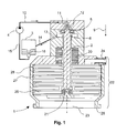
- FIG. 1 shows a vacuum pump 1, which is operated in a head-over arrangement.
- the flange 28 is at the lower end of the vacuum pump.
- the lower end is to be understood in relation to the direction of gravity, the is indicated by the direction of the arrowhead of the arrow 9.
- the flange 28 is connectable to a device to be evacuated. With the flange surrounding the gas inlet 23, the vacuum region 22 of the vacuum pump begins.
- the pump-active elements are provided. As a result of their action, a gas pressure well below atmospheric pressure is created in the device connected to the vacuum pump and within the vacuum range.
- the pump-active elements comprise blades carrying rotor disks 25, which are arranged on a vacuum pump rotor 2.
- the vacuum-side end of the vacuum pump rotor 2 is rotatably supported by a wear and lubricant-free permanent magnetic bearing 21.
- a motor 20 rotates the vacuum pump rotor in rapid rotation, in which the pump-active elements deploy the pumping action.
- the vacuum pump rotor 2 is rotatably supported by a rolling bearing 5 at the opposite end of the permanent bearing.
- This rolling bearing is supplied with lubricant by a lubricant circuit.
- the lubricant circuit contains a lubricant reservoir chamber 3 from which lubricant passes via a lubricant pump inlet 15 to a lubricant pump 4, which keeps the lubricant circuit in motion with its delivery rate.
- an external inlet 10 leads to the housing of the vacuum pump and is connected there to an internal inlet 11. This opens in the region of a spray nut 12. This is mounted on the end of the vacuum pump rotor and has a conical shape.
- the rotation of the vacuum pump rotor causes the injection nut to rotate so that there is a lubricant flow through the centrifugal force along the cone.
- the injection nut promotes that Lubricant in the rolling bearing. From there it enters an internal return 13, which is connected to an external return 14.
- the external return eventually returns the lubricant to the lubricant reservoir.
- the described flow of the lubricant is in the FIG. 1 indicated by arrows.
- a lubricant collecting chamber 6 is arranged between the rolling bearing and flange and thus in the direction of gravity below the rolling bearing. Lubricant exiting the rolling bearing is collected in it before it enters the internal return 13. When switching off the vacuum pump, this is particularly important, because in a previously flooded with air vacuum pump, the lubricant pump is running, lubricant passes through the lubricant pump inlet 15 back into the lubricant reservoir 3. It displaces the air there, which then lubricant through the external return 14th pushes into the vacuum pump. This lubricant is collected by the lubricant collecting chamber 6. This prevents the circulating partial amount of the total lubricant from entering the vacuum area along the vacuum pump rotor.
- the lubricant reservoir chamber 16 has a limiting means.
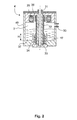
- FIG. 2 shows the section through a lubricant pump 4 ', the housing 40 forms the lubricant reservoir.
- the lubricant reservoir chamber 3 ' is penetrated by a hollow axle 32, on which a rotor 33 is slidably mounted. It has a helical channel 34, which promotes lubricant into the hollow axis upon rotation of the rotor. From there it exits through the outlet 31 from the lubricant pump and into the lubricant circuit. Through an inlet 30, the lubricant from the lubricant circuit comes back into the lubricant reservoir chamber.
- the rotor is rotated by a drive means comprising the coils 35 and the rotor-side magnets 36 in rotation.
- a sleeve-shaped section 16 ' is provided, which surrounds the rotor in the region of the outlet of the lubricant reservoir chamber. Through this sleeve remains in the lubricant reservoir up to a height H standing, non-circulated lubricant amount 37. Since the circulating amount of lubricant that is heated in the lubrication of the bearing, with this cooler amount of lubricant in exchange, the temperature of the lubricant is compared to a total Circulation of the total lowered. This further increases the service life of the rolling bearing.
Landscapes
- Engineering & Computer Science (AREA)
- Mechanical Engineering (AREA)
- General Engineering & Computer Science (AREA)
- Non-Positive Displacement Air Blowers (AREA)
- Rolling Contact Bearings (AREA)
Abstract
Description
- Die Erfindung betrifft eine Vakuumpumpe mit einem Rotor und mit einem Schmiermittelkreislauf, der eine Schmiermittelvorratskammer und eine Schmiermittelpumpe enthält, und der zur Schmierung eines den Rotor drehbar unterstützenden Wälzlagers dient.
- Vakuumpumpen mit schnelldrehenden Rotoren, insbesondere Turbomolekularpumpen, weisen häufig Wälzlager zur Lagerung des Rotors auf. Aufgrund der schnellen Drehung, die im Bereich von einigen zehntausend Umdrehungen pro Minute liegt, ist die Versorgung des Wälzlagers mit Schmiermittel für die Lebensdauer des Lagers entscheidend. Es ist bekannt, einen Schmiermittelkreislauf vorzusehen, bei dem Schmiermittel einer Schmiermittelvorratskammer entnommen und dem Wälzlager zugeführt wird. Von dort fließt es dann zurück in die Schmiermittelvorratskammer. Der Schmiermittelkreislauf wird von einer Schmiermittelpumpe in Gang gehalten. Die Anforderungen an den Schmiermittelkreislauf werden dadurch erhöht, dass die Befestigung der Vakuumpumpe in verschiedenen Orientierungen in Bezug zur Schwerkraftrichtung an der zu evakuierenden Anlage möglich sein soll.
- Ein Beispiel für eine Anordnung, mit der das gelingen kann, gibt die
EP-A 1 477 721 . Diese Schrift stellt eine Schmiermittelpumpe mit einer Spindeln mit zwei Förderköpfen vor, von denen jeweils eine in das in der Schmiermittelkammer befindliche Schmiermittel eingetaucht ist. Auf diese Art wird eine Förderung von Schmiermittel in jeder Orientierung erreicht. - Man stellt jedoch fest, dass die Lebensdauer im Kopfüberbetrieb, wenn der Flansch der Vakuumpumpe in Bezug zur Schwerkraftrichtung unterhalb des Wälzlagers angeordnet ist, geringer als bei umgekehrter Ausrichtung der Vakuumpumpe ist.
- Daher war es Aufgabe des Erfinder, eine Vakuumpumpe zu schaffen, deren Lebensdauer insbesondere im Kopfüberbetrieb verlängert ist.
- Diese Aufgabe wird gelöst durch eine Vakuumpumpe mit den Merkmalen des ersten Anspruchs. Die Ansprüche 2 bis 6 geben vorteilhafte Weiterbildungen der Erfindung an.
- Eine Schmiermittelsammelkammer, die zusätzlich zur Schmiermittelvorratskammer vorgesehen und innerhalb der Vakuumpumpe zwischen Wälzlager und Flansch angeordnet ist, ermöglicht es, bis zum Stillstand des Rotors Schmiermittel in das Wälzlager zu fördern. Dieses Schmiermittel wird in der Schmiermittelsammelkammer aufgefangen und kann nicht in den Vakuumbereich der Vakuumpumpe gelangen. Dies verhindert zum einen Kontamination des Vakuumbereichs mit Schmiermittel, zum anderen werden Schmiermittelverluste erheblich verringert. Lebensdauerverringerung durch Schmiermittelverluste treten daher nicht mehr auf. Da jederzeit Schmierung gewährleistet ist, werden Betriebszustände mit mangelndem Schmiermitteleinsatz vermieden. Dadurch wird der Verschleiß herabgesetzt und somit die Lebensdauer erhöht.
- In einer vorteilhaften Weiterbildung ist die Schmiermittelvorratskammer Teil der Schmiermittelpumpe, wodurch ein sehr platzsparender Aufbau mit wenigen Bauteilen erreicht wird.
- Eine Verunreinigung des Vakuumbereichs wird verhindert, indem in einer Weiterbildung das Volumen der Schmiermittelsammelkammer derart bemessen ist, dass sie die komplette, im Umlauf befindliche Menge des Schmiermittels aufnehmen kann.
- In einer anderen Weiterbildung weist die Schmiermittelpumpe ein Antriebsmittel auf, durch dessen Gestaltung die Förderleistung der Schmiermittelpumpe unabhängig von der Drehzahl des Rotors ist. Damit wird bei in den Stillstand übergehenden Rotor weiterhin Schmiermittel dem Wälzlager zugeführt, wodurch ein Abreißen der Schmierung verhindert wird. Dadurch wird die Lebensdauer des Wälzlagers weiter erhöht.
- Die Erfindung lässt sich vorteilhaft weiterbilden, indem die Schmiermittelvorratskammer ein Begrenzungsmittel aufwiest, das eine vollständige Entnahme des Schmiermittels verhindert. Dadurch bleibt immer eine Mindestmenge Schmiermittel in der Schmiermittelvorratskammer, die dort Abkühlen kann. Etwaige durch den Umlauf in das Schmiermittel gelangte Festkörper können in dieser Mindestmenge ausfallen. Zudem ist die Nutzungszeit pro Schmiermittelmenge geringer.
- Eine einfache Ausführung des Begrenzungsmittels ist ein Kragen, der um den Auslass der Schmiermittelvorratskammer herum angeordnet ist.
- Anhand eines Ausführungsbeispiels soll die Erfindung näher erläutert und weitere Vorteile aufgezeigt werden. Es zeigen:
- Fig. 1:
- Schnitt durch eine Vakuumpumpe mit Schmiermittelkreislauf
- Fig. 2:
- Schnitt durch eine Schmiermittelpumpe, die gemäß einer Weiterbildung der Erfindung eine Schmiermittelvorratskammer umfasst.
-
Figur 1 zeigt eine Vakuumpumpe 1, die in Kopfüberanordnung betrieben wird. Das bedeutet, dass sich der Flansch 28 am unteren Ende der Vakuumpumpe befindet. Das untere Ende ist dabei in Bezug auf die Schwerkraftrichtung zu verstehen, die durch die Richtung der Pfeilspitze des Pfeils 9 angezeigt wird. Der Flansch 28 ist mit einer zu evakuierenden Einrichtung verbindbar. Mit dem Flansch, der den Gaseinlass 23 umgibt, beginnt der Vakuumbereich 22 der Vakuumpumpe. In diesem sind die pumpaktiven Elemente vorgesehen. Durch deren Wirkung entsteht in der mit der Vakuumpumpe verbundenen Einrichtung und innerhalb des Vakuumbereichs ein Gasdruck weit unterhalb des Atmosphärendrucks. Im Beispiel umfassen die pumpaktiven Elemente Schaufeln tragende Rotorscheiben 25, die an einem Vakuumpumpenrotor 2 angeordnet sind. Ihnen stehen ebenfalls Schaufeln tragende Statorscheiben 26 gegenüber, wobei sich Rotor- und Statorscheiben entlang des Vakuumpumpenrotors abwechseln. Die Statorscheiben werden durch Distanzringe 27 auf axialem Abstand gehalten. Das durch die pumpaktiven Elemente verdichtete Gas wird durch einen Gasauslass 24 aus der Pumpe ausgestoßen. Das vakuumseitige Ende des Vakuumpumpenrotors 2 ist durch ein verschleiß- und schmiermittelfreies Permanenmagnetlager 21 drehbar unterstützt. Ein Motor 20 versetzt den Vakuumpumpenrotor in schnelle Drehung, bei der die pumpaktiven Elemente die Pumpwirkung entfalten. - Der Vakuumpumpenrotor 2 wird durch ein Wälzlager 5 am dem Permanentlager gegenüberliegenden Ende drehbar unterstützt. Dieses Wälzlager wird durch einen Schmiermittelkreislauf mit Schmiermittel versorgt. Der Schmiermittelkreislauf enthält eine Schmiermittelvorratskammer 3 von der Schmiermittel über einen Schmiermittelpumpenzulauf 15 zu einer Schmiermittelpumpe 4 gelangt, welche mit ihrer Förderleistung den Schmiermittelkreislauf in Gang hält. Von der Schmiermittelpumpe führt ein externer Zulauf 10 zum Gehäuse der Vakuumpumpe und ist dort mit einem internen Zulauf 11 verbunden. Dieser mündet im Bereich einer Spritzmutter 12. Diese ist auf dem Ende des Vakuumpumpenrotors befestigt und weist eine konische Gestalt auf. Durch die Drehung des Vakuumpumpenrotors dreht sich die Spritzmutter, so dass entlang des Konus eine Föderung von Schmiermittel durch Fliehkraftwirkung stattfindet. Die Spritzmutter fördert das Schmiermittel in das Wälzlager. Von dort gelangt es in einen internen Rücklauf 13, der mit einem externen Rücklauf 14 verbunden ist. Durch den externen Rücklauf gelangt das Schmiermittel schließlich zurück in die Schmiermittelvorratskammer. Der beschriebene Fluss des Schmiermittels ist in der
Figur 1 durch Pfeile angedeutet. - Zwischen Wälzlager und Flansch und damit in Schwerkraftrichtung unterhalb des Wälzlagers ist eine Schmiermittelsammelkammer 6 angeordnet. Schmiermittel, welches aus dem Wälzlager austritt, wird in ihr gesammelt, bevor es in den internen Rücklauf 13 gelangt. Beim Abschalten der Vakuumpumpe ist dies besonders wichtig, denn wenn bei einer bereits mit Luft gefluteten Vakuumpumpe die Schmiermittelpumpe abgeschaltetet wird, läuft Schmiermittel durch den Schmiermittelpumpenzulauf 15 zurück in die Schmiermittelvorratskammer 3. Es verdrängt die dort befindliche Luft, welche dann Schmiermittel durch den externen Rücklauf 14 in die Vakuumpumpe drückt. Dieses Schmiermittel wird von der Schmiermittelsammelkammer 6 aufgefangen. Hierdurch wird verhindert, dass die im Umlauf befindliche Teilmenge des gesamten Schmiermittels entlang der Vakuumpumpenrotors in den Vakuumbereich eintritt. Daher wird eine Kontamination der an die Vakuumpumpe angeschlossenen Kammer verhindert. Gleichzeitig wird auch verhindert, dass Schmiermittel aus dem Schmiermittelkreislauf verloren geht, indem es in den Vakuumbereich eintritt. Von dort kann es nicht mehr in den Schmiermittelkreislauf zurückgebracht werden. Das Volumen der Schmiermittelsammelkammer ist derart bemessen, dass es die im Umlauf befindliche Schmiermittelmenge aufnehmen kann. Dadurch ist der Eintrag von Schmiermittel in den Vakuumbereich noch zuverlässiger unterbunden. Durch die Schmiermittelsammelkammer ist es möglich, bis zum Stillstand des Rotors Schmiermittel in das Wälzlager zu fördern, ohne dass es zur Kontamination des Vakuumbereichs kommen kann. Um die Menge des im Umlauf befindlichen Schmiermittels zu begrenzen, weist die Schmiermittelvorratskammer ein Begrenzungsmittel 16 auf.
-
Figur 2 zeigt den Schnitt durch eine Schmiermittelpumpe 4', deren Gehäuse 40 die Schmiermittelvorratskammer bildet. Die Schmiermittelvorratskammer 3' wird von einer hohlen Achse 32 durchsetzt, auf der ein Rotor 33 gleitgelagert ist. Er weist einen schraubenförmigen Kanal 34 auf, der bei Drehung des Rotors Schmiermittel in die hohle Achse hineinfördert. Von dort tritt es durch den Auslass 31 aus der Schmiermittelpumpe aus und in den Schmiermittelkreislauf ein. Durch einen Einlass 30 kommt das Schmiermittel aus dem Schmiermittelkreislauf wieder in die Schmiermittelvorratskammer hinein. Der Rotor wird von einem die Spulen 35 und die rotorseitigen Magnete 36 umfassenden Antriebsmittel in Drehung versetzt. Um die im Schmiermittelkreislauf umlaufende Schmiermittelmenge zu begrenzen, ist ein hülsenförmiger Abschnitt 16' vorgesehen, der den Rotor im Bereich des Auslasses der Schmiermittelvorratskammer umgibt. Durch diese Hülse verbleibt in der Schmiermittelsvorratskammer eine bis zur Höhe H stehende, nicht-umgewälzte Schmiermittelmenge 37. Da die umlaufende Schmiermittelmenge, welche bei der Schmierung des Wälzlagers erwärmt wird, mit dieser kühleren Schmiermittelmenge in Austausch steht, wird die Temperatur des Schmiermittels insgesamt gegenüber einem Umlauf der Gesamtmenge abgesenkt. Damit wird die Lebensdauer des Wälzlagers weiter erhöht.
Claims (6)
- Vakuumpumpe (1) mit einem Flansch (28), einem Rotor (2) und mit einem Schmiermittelkreislauf, der eine Schmiermittelvorratskammer (3) und eine Schmiermittelpumpe (4; 4') enthält, und der zur Schmierung eines den Rotor drehbar unterstützenden Wälzlagers (5) dient, dadurch gekennzeichnet, dass als Bestandteil des Schmiermittelkreislaufs eine Schmiermittelsammelkammer (6) innerhalb der Vakuumpumpe zwischen Flansch und Wälzlager angeordnet ist.
- Vakuumpumpe nach Anspruch 1, dadurch gekennzeichnet, dass die Schmiermittelvorratskammer (3) Teil der Schmiermittelpumpe (4; 4') ist.
- Vakuumpumpe nach Anspruch 1 oder 2, dadurch gekennzeichnet, dass das Volumen der Schmiermittelsammelkammer (6) derart bemessen ist, die im Umlauf befindliche Menge eines im Schmiermittelkreislauf befindlichen Schmiermittels aufzunehmen.
- Vakuumpumpe nach einem der vorhergehenden Ansprüche, dadurch gekennzeichnet, dass die Schmiermittelpumpe (4; 4') ein Antriebsmittel (35, 36) aufweist, durch dessen Gestaltung die Förderleistung der Schmiermittelpumpe unabhängig von der Drehzahl des Vakuumpumpenrotors ist.
- Vakuumpumpe nach einem der vorhergehenden Ansprüche, dadurch gekennzeichnet, dass die Schmiermittelvorratskammer (3) ein Begrenzungsmittel (16; 16') aufweist, das eine vollständige Entnahme des Schmiermittels verhindern.
- Vakuumpumpe nach Anspruch 5, dadurch gekennzeichnet, dass das Begrenzungsmittel einen um einen Auslass der Schmiermittelvorratskammer (3) herum angeordneten Kragen (16') umfasst.
Applications Claiming Priority (1)
| Application Number | Priority Date | Filing Date | Title |
|---|---|---|---|
| DE200710054632 DE102007054632A1 (de) | 2007-11-15 | 2007-11-15 | Vakuumpumpe |
Publications (3)
| Publication Number | Publication Date |
|---|---|
| EP2060795A2 true EP2060795A2 (de) | 2009-05-20 |
| EP2060795A3 EP2060795A3 (de) | 2013-11-06 |
| EP2060795B1 EP2060795B1 (de) | 2019-03-20 |
Family
ID=40042850
Family Applications (1)
| Application Number | Title | Priority Date | Filing Date |
|---|---|---|---|
| EP08018521.8A Active EP2060795B1 (de) | 2007-11-15 | 2008-10-23 | Vakuumpumpe |
Country Status (3)
| Country | Link |
|---|---|
| EP (1) | EP2060795B1 (de) |
| JP (1) | JP5412087B2 (de) |
| DE (1) | DE102007054632A1 (de) |
Cited By (4)
| Publication number | Priority date | Publication date | Assignee | Title |
|---|---|---|---|---|
| US20140356146A1 (en) * | 2013-05-29 | 2014-12-04 | Pfeiffer Vacuum Gmbh | Vacuum pump |
| EP2557316A3 (de) * | 2011-08-10 | 2015-09-30 | Pfeiffer Vacuum GmbH | Vakuumpumpe |
| GB2552700A (en) * | 2016-08-04 | 2018-02-07 | Edwards Ltd | Turbomolecular pump lubricant supply systems |
| EP3473858A1 (de) * | 2017-10-17 | 2019-04-24 | Pfeiffer Vacuum Gmbh | Verfahren zur lebensdaueroptimierung von wälzlagern einer vakuumpumpe |
Families Citing this family (4)
| Publication number | Priority date | Publication date | Assignee | Title |
|---|---|---|---|---|
| DE102012220040A1 (de) * | 2012-11-02 | 2014-05-08 | Pfeiffer Vacuum Gmbh | Vakuumpumpe |
| DE102012023727B4 (de) * | 2012-12-05 | 2020-03-19 | Pfeiffer Vacuum Gmbh | Schmiermitteleinrichtung für ein Wälzlager |
| BE1022719B1 (nl) * | 2015-02-13 | 2016-08-23 | Atlas Copco Airpower Naamloze Vennootschap | Compressorinrichting |
| JP7141332B2 (ja) * | 2018-12-28 | 2022-09-22 | 株式会社荏原製作所 | 真空ポンプ装置 |
Citations (1)
| Publication number | Priority date | Publication date | Assignee | Title |
|---|---|---|---|---|
| EP1477721A2 (de) | 2003-05-13 | 2004-11-17 | Pfeiffer Vacuum GmbH | Einrichtung zur Ölversorgung der Lagerstellen einer rotierenden Welle |
Family Cites Families (6)
| Publication number | Priority date | Publication date | Assignee | Title |
|---|---|---|---|---|
| IT1032818B (it) * | 1975-05-06 | 1979-06-20 | Rava E | Perfezionamento alle pompe turbomo lecolari |
| US4140441A (en) * | 1977-04-11 | 1979-02-20 | Patterson Williams G | Turbomolecular pump lubrication system |
| JPS6053695A (ja) * | 1983-09-02 | 1985-03-27 | Hitachi Ltd | タ−ボ分子ポンプ |
| DE3817290A1 (de) * | 1988-05-20 | 1989-11-30 | Leybold Ag | Turbomolekularpumpe |
| DE8909636U1 (de) * | 1989-08-11 | 1990-12-06 | Leybold AG, 6450 Hanau | Vakuumpumpe mit einem Rotor und mit unter Vakuum betriebenen Rotorlagerungen |
| JP2978339B2 (ja) * | 1992-09-21 | 1999-11-15 | 株式会社日立製作所 | 真空ポンプ |
-
2007
- 2007-11-15 DE DE200710054632 patent/DE102007054632A1/de not_active Ceased
-
2008
- 2008-10-23 EP EP08018521.8A patent/EP2060795B1/de active Active
- 2008-11-07 JP JP2008286289A patent/JP5412087B2/ja active Active
Patent Citations (1)
| Publication number | Priority date | Publication date | Assignee | Title |
|---|---|---|---|---|
| EP1477721A2 (de) | 2003-05-13 | 2004-11-17 | Pfeiffer Vacuum GmbH | Einrichtung zur Ölversorgung der Lagerstellen einer rotierenden Welle |
Cited By (6)
| Publication number | Priority date | Publication date | Assignee | Title |
|---|---|---|---|---|
| EP2557316A3 (de) * | 2011-08-10 | 2015-09-30 | Pfeiffer Vacuum GmbH | Vakuumpumpe |
| US20140356146A1 (en) * | 2013-05-29 | 2014-12-04 | Pfeiffer Vacuum Gmbh | Vacuum pump |
| GB2552700A (en) * | 2016-08-04 | 2018-02-07 | Edwards Ltd | Turbomolecular pump lubricant supply systems |
| US11111927B2 (en) | 2016-08-04 | 2021-09-07 | Edwards Limited | Turbomolecular pump lubricant supply systems |
| US11746792B2 (en) | 2016-08-04 | 2023-09-05 | Edwards Limited | Turbomolecular pump lubricant supply systems |
| EP3473858A1 (de) * | 2017-10-17 | 2019-04-24 | Pfeiffer Vacuum Gmbh | Verfahren zur lebensdaueroptimierung von wälzlagern einer vakuumpumpe |
Also Published As
| Publication number | Publication date |
|---|---|
| JP5412087B2 (ja) | 2014-02-12 |
| JP2009121467A (ja) | 2009-06-04 |
| EP2060795A3 (de) | 2013-11-06 |
| EP2060795B1 (de) | 2019-03-20 |
| DE102007054632A1 (de) | 2009-05-20 |
Similar Documents
| Publication | Publication Date | Title |
|---|---|---|
| EP2060795B1 (de) | Vakuumpumpe | |
| EP2060794B1 (de) | Vakuumpumpe mit Schmiermittelpumpe | |
| DE69006453T2 (de) | Schmierölrückgewinnungssystem. | |
| EP1394406A2 (de) | Getriebelose Windturbine mit vielpoligem Synchrongenerator | |
| EP2557316B1 (de) | Vakuumpumpe | |
| DE102015207341B4 (de) | Verdichter und Kraftfahrzeug | |
| EP1936200B1 (de) | Schmiermittelgedichtete Drehschiebervakuumpumpe | |
| EP2626563B1 (de) | Pumpe, sowie eine rezikulationseinrichtung für eine pumpe | |
| CH714176A1 (de) | Zentrifugalpumpe für kryogene Fördermedien. | |
| DE2814266A1 (de) | Schmiersystem fuer hermetischen kaelteverdichter | |
| DE1653664A1 (de) | Selbstansaugende Zentrifugalpumpe | |
| DE102012023727B4 (de) | Schmiermitteleinrichtung für ein Wälzlager | |
| DE112023001556T5 (de) | Variable einlassleitschaufelvorrichtung und kompressor mit dieser | |
| DE102014102272B4 (de) | Pumpe | |
| EP1757816B1 (de) | Einrichtung für Pumpen | |
| DE69723488T2 (de) | Seitenkanalpumpe | |
| WO1990014523A1 (de) | Selbstfördereinrichtung für die schmierung eines lagers | |
| DD262263A5 (de) | Mehrstufige pumpe | |
| EP2071123B1 (de) | Drehschiebervakuumpumpe mit modifizierter Wellenlagerung | |
| DE102021133447A1 (de) | Magnetkupplungspumpenanordnung | |
| DE102009023188B4 (de) | Strömungsmaschine mit im Innern einer Hohlwelle angeordnetem Laufrad | |
| EP1999387A1 (de) | Hydrodynamisches gleitlager | |
| DE271478C (de) | ||
| DE19814485A1 (de) | Mehrstufiges Turbogebläse | |
| EP3673178B1 (de) | Rohr-axialpumpe |
Legal Events
| Date | Code | Title | Description |
|---|---|---|---|
| PUAI | Public reference made under article 153(3) epc to a published international application that has entered the european phase |
Free format text: ORIGINAL CODE: 0009012 |
|
| AK | Designated contracting states |
Kind code of ref document: A2 Designated state(s): AT BE BG CH CY CZ DE DK EE ES FI FR GB GR HR HU IE IS IT LI LT LU LV MC MT NL NO PL PT RO SE SI SK TR |
|
| AX | Request for extension of the european patent |
Extension state: AL BA MK RS |
|
| PUAL | Search report despatched |
Free format text: ORIGINAL CODE: 0009013 |
|
| AK | Designated contracting states |
Kind code of ref document: A3 Designated state(s): AT BE BG CH CY CZ DE DK EE ES FI FR GB GR HR HU IE IS IT LI LT LU LV MC MT NL NO PL PT RO SE SI SK TR |
|
| AX | Request for extension of the european patent |
Extension state: AL BA MK RS |
|
| RIC1 | Information provided on ipc code assigned before grant |
Ipc: F04D 29/059 20060101ALI20131002BHEP Ipc: F04D 19/04 20060101AFI20131002BHEP Ipc: F04D 29/063 20060101ALI20131002BHEP |
|
| 17P | Request for examination filed |
Effective date: 20140506 |
|
| RBV | Designated contracting states (corrected) |
Designated state(s): AT BE BG CH CY CZ DE DK EE ES FI FR GB GR HR HU IE IS IT LI LT LU LV MC MT NL NO PL PT RO SE SI SK TR |
|
| AKX | Designation fees paid |
Designated state(s): AT BE BG CH CY CZ DE DK EE ES FI FR GB GR HR HU IE IS IT LI LT LU LV MC MT NL NO PL PT RO SE SI SK TR |
|
| STAA | Information on the status of an ep patent application or granted ep patent |
Free format text: STATUS: EXAMINATION IS IN PROGRESS |
|
| 17Q | First examination report despatched |
Effective date: 20180223 |
|
| GRAP | Despatch of communication of intention to grant a patent |
Free format text: ORIGINAL CODE: EPIDOSNIGR1 |
|
| STAA | Information on the status of an ep patent application or granted ep patent |
Free format text: STATUS: GRANT OF PATENT IS INTENDED |
|
| INTG | Intention to grant announced |
Effective date: 20181004 |
|
| GRAS | Grant fee paid |
Free format text: ORIGINAL CODE: EPIDOSNIGR3 |
|
| GRAA | (expected) grant |
Free format text: ORIGINAL CODE: 0009210 |
|
| STAA | Information on the status of an ep patent application or granted ep patent |
Free format text: STATUS: THE PATENT HAS BEEN GRANTED |
|
| AK | Designated contracting states |
Kind code of ref document: B1 Designated state(s): AT BE BG CH CY CZ DE DK EE ES FI FR GB GR HR HU IE IS IT LI LT LU LV MC MT NL NO PL PT RO SE SI SK TR |
|
| REG | Reference to a national code |
Ref country code: GB Ref legal event code: FG4D Free format text: NOT ENGLISH |
|
| REG | Reference to a national code |
Ref country code: CH Ref legal event code: EP |
|
| REG | Reference to a national code |
Ref country code: DE Ref legal event code: R096 Ref document number: 502008016655 Country of ref document: DE |
|
| REG | Reference to a national code |
Ref country code: AT Ref legal event code: REF Ref document number: 1110840 Country of ref document: AT Kind code of ref document: T Effective date: 20190415 |
|
| REG | Reference to a national code |
Ref country code: IE Ref legal event code: FG4D Free format text: LANGUAGE OF EP DOCUMENT: GERMAN |
|
| REG | Reference to a national code |
Ref country code: NL Ref legal event code: MP Effective date: 20190320 |
|
| PG25 | Lapsed in a contracting state [announced via postgrant information from national office to epo] |
Ref country code: SE Free format text: LAPSE BECAUSE OF FAILURE TO SUBMIT A TRANSLATION OF THE DESCRIPTION OR TO PAY THE FEE WITHIN THE PRESCRIBED TIME-LIMIT Effective date: 20190320 Ref country code: LT Free format text: LAPSE BECAUSE OF FAILURE TO SUBMIT A TRANSLATION OF THE DESCRIPTION OR TO PAY THE FEE WITHIN THE PRESCRIBED TIME-LIMIT Effective date: 20190320 Ref country code: NO Free format text: LAPSE BECAUSE OF FAILURE TO SUBMIT A TRANSLATION OF THE DESCRIPTION OR TO PAY THE FEE WITHIN THE PRESCRIBED TIME-LIMIT Effective date: 20190620 Ref country code: FI Free format text: LAPSE BECAUSE OF FAILURE TO SUBMIT A TRANSLATION OF THE DESCRIPTION OR TO PAY THE FEE WITHIN THE PRESCRIBED TIME-LIMIT Effective date: 20190320 |
|
| REG | Reference to a national code |
Ref country code: LT Ref legal event code: MG4D |
|
| PG25 | Lapsed in a contracting state [announced via postgrant information from national office to epo] |
Ref country code: BG Free format text: LAPSE BECAUSE OF FAILURE TO SUBMIT A TRANSLATION OF THE DESCRIPTION OR TO PAY THE FEE WITHIN THE PRESCRIBED TIME-LIMIT Effective date: 20190620 Ref country code: HR Free format text: LAPSE BECAUSE OF FAILURE TO SUBMIT A TRANSLATION OF THE DESCRIPTION OR TO PAY THE FEE WITHIN THE PRESCRIBED TIME-LIMIT Effective date: 20190320 Ref country code: NL Free format text: LAPSE BECAUSE OF FAILURE TO SUBMIT A TRANSLATION OF THE DESCRIPTION OR TO PAY THE FEE WITHIN THE PRESCRIBED TIME-LIMIT Effective date: 20190320 Ref country code: LV Free format text: LAPSE BECAUSE OF FAILURE TO SUBMIT A TRANSLATION OF THE DESCRIPTION OR TO PAY THE FEE WITHIN THE PRESCRIBED TIME-LIMIT Effective date: 20190320 Ref country code: GR Free format text: LAPSE BECAUSE OF FAILURE TO SUBMIT A TRANSLATION OF THE DESCRIPTION OR TO PAY THE FEE WITHIN THE PRESCRIBED TIME-LIMIT Effective date: 20190621 |
|
| PG25 | Lapsed in a contracting state [announced via postgrant information from national office to epo] |
Ref country code: ES Free format text: LAPSE BECAUSE OF FAILURE TO SUBMIT A TRANSLATION OF THE DESCRIPTION OR TO PAY THE FEE WITHIN THE PRESCRIBED TIME-LIMIT Effective date: 20190320 Ref country code: SK Free format text: LAPSE BECAUSE OF FAILURE TO SUBMIT A TRANSLATION OF THE DESCRIPTION OR TO PAY THE FEE WITHIN THE PRESCRIBED TIME-LIMIT Effective date: 20190320 Ref country code: PT Free format text: LAPSE BECAUSE OF FAILURE TO SUBMIT A TRANSLATION OF THE DESCRIPTION OR TO PAY THE FEE WITHIN THE PRESCRIBED TIME-LIMIT Effective date: 20190720 Ref country code: EE Free format text: LAPSE BECAUSE OF FAILURE TO SUBMIT A TRANSLATION OF THE DESCRIPTION OR TO PAY THE FEE WITHIN THE PRESCRIBED TIME-LIMIT Effective date: 20190320 Ref country code: RO Free format text: LAPSE BECAUSE OF FAILURE TO SUBMIT A TRANSLATION OF THE DESCRIPTION OR TO PAY THE FEE WITHIN THE PRESCRIBED TIME-LIMIT Effective date: 20190320 |
|
| PG25 | Lapsed in a contracting state [announced via postgrant information from national office to epo] |
Ref country code: PL Free format text: LAPSE BECAUSE OF FAILURE TO SUBMIT A TRANSLATION OF THE DESCRIPTION OR TO PAY THE FEE WITHIN THE PRESCRIBED TIME-LIMIT Effective date: 20190320 |
|
| PG25 | Lapsed in a contracting state [announced via postgrant information from national office to epo] |
Ref country code: IS Free format text: LAPSE BECAUSE OF FAILURE TO SUBMIT A TRANSLATION OF THE DESCRIPTION OR TO PAY THE FEE WITHIN THE PRESCRIBED TIME-LIMIT Effective date: 20190720 |
|
| REG | Reference to a national code |
Ref country code: DE Ref legal event code: R097 Ref document number: 502008016655 Country of ref document: DE |
|
| PLBE | No opposition filed within time limit |
Free format text: ORIGINAL CODE: 0009261 |
|
| STAA | Information on the status of an ep patent application or granted ep patent |
Free format text: STATUS: NO OPPOSITION FILED WITHIN TIME LIMIT |
|
| PG25 | Lapsed in a contracting state [announced via postgrant information from national office to epo] |
Ref country code: DK Free format text: LAPSE BECAUSE OF FAILURE TO SUBMIT A TRANSLATION OF THE DESCRIPTION OR TO PAY THE FEE WITHIN THE PRESCRIBED TIME-LIMIT Effective date: 20190320 |
|
| 26N | No opposition filed |
Effective date: 20200102 |
|
| PG25 | Lapsed in a contracting state [announced via postgrant information from national office to epo] |
Ref country code: SI Free format text: LAPSE BECAUSE OF FAILURE TO SUBMIT A TRANSLATION OF THE DESCRIPTION OR TO PAY THE FEE WITHIN THE PRESCRIBED TIME-LIMIT Effective date: 20190320 |
|
| PG25 | Lapsed in a contracting state [announced via postgrant information from national office to epo] |
Ref country code: TR Free format text: LAPSE BECAUSE OF FAILURE TO SUBMIT A TRANSLATION OF THE DESCRIPTION OR TO PAY THE FEE WITHIN THE PRESCRIBED TIME-LIMIT Effective date: 20190320 |
|
| PG25 | Lapsed in a contracting state [announced via postgrant information from national office to epo] |
Ref country code: MC Free format text: LAPSE BECAUSE OF FAILURE TO SUBMIT A TRANSLATION OF THE DESCRIPTION OR TO PAY THE FEE WITHIN THE PRESCRIBED TIME-LIMIT Effective date: 20190320 |
|
| REG | Reference to a national code |
Ref country code: CH Ref legal event code: PL |
|
| PG25 | Lapsed in a contracting state [announced via postgrant information from national office to epo] |
Ref country code: LU Free format text: LAPSE BECAUSE OF NON-PAYMENT OF DUE FEES Effective date: 20191023 Ref country code: CH Free format text: LAPSE BECAUSE OF NON-PAYMENT OF DUE FEES Effective date: 20191031 Ref country code: LI Free format text: LAPSE BECAUSE OF NON-PAYMENT OF DUE FEES Effective date: 20191031 |
|
| REG | Reference to a national code |
Ref country code: BE Ref legal event code: MM Effective date: 20191031 |
|
| PG25 | Lapsed in a contracting state [announced via postgrant information from national office to epo] |
Ref country code: BE Free format text: LAPSE BECAUSE OF NON-PAYMENT OF DUE FEES Effective date: 20191031 |
|
| PG25 | Lapsed in a contracting state [announced via postgrant information from national office to epo] |
Ref country code: IE Free format text: LAPSE BECAUSE OF NON-PAYMENT OF DUE FEES Effective date: 20191023 Ref country code: FR Free format text: LAPSE BECAUSE OF NON-PAYMENT OF DUE FEES Effective date: 20191031 |
|
| REG | Reference to a national code |
Ref country code: AT Ref legal event code: MM01 Ref document number: 1110840 Country of ref document: AT Kind code of ref document: T Effective date: 20191023 |
|
| PG25 | Lapsed in a contracting state [announced via postgrant information from national office to epo] |
Ref country code: AT Free format text: LAPSE BECAUSE OF NON-PAYMENT OF DUE FEES Effective date: 20191023 |
|
| PG25 | Lapsed in a contracting state [announced via postgrant information from national office to epo] |
Ref country code: CY Free format text: LAPSE BECAUSE OF FAILURE TO SUBMIT A TRANSLATION OF THE DESCRIPTION OR TO PAY THE FEE WITHIN THE PRESCRIBED TIME-LIMIT Effective date: 20190320 |
|
| PG25 | Lapsed in a contracting state [announced via postgrant information from national office to epo] |
Ref country code: MT Free format text: LAPSE BECAUSE OF FAILURE TO SUBMIT A TRANSLATION OF THE DESCRIPTION OR TO PAY THE FEE WITHIN THE PRESCRIBED TIME-LIMIT Effective date: 20190320 Ref country code: HU Free format text: LAPSE BECAUSE OF FAILURE TO SUBMIT A TRANSLATION OF THE DESCRIPTION OR TO PAY THE FEE WITHIN THE PRESCRIBED TIME-LIMIT; INVALID AB INITIO Effective date: 20081023 |
|
| PGFP | Annual fee paid to national office [announced via postgrant information from national office to epo] |
Ref country code: GB Payment date: 20251022 Year of fee payment: 18 |
|
| PGFP | Annual fee paid to national office [announced via postgrant information from national office to epo] |
Ref country code: IT Payment date: 20251024 Year of fee payment: 18 |
|
| PGFP | Annual fee paid to national office [announced via postgrant information from national office to epo] |
Ref country code: CZ Payment date: 20251015 Year of fee payment: 18 |
|
| PGFP | Annual fee paid to national office [announced via postgrant information from national office to epo] |
Ref country code: DE Payment date: 20251229 Year of fee payment: 18 |