EP2060813A1 - Keilverzahnung zur kraftübertragung - Google Patents
Keilverzahnung zur kraftübertragung Download PDFInfo
- Publication number
- EP2060813A1 EP2060813A1 EP07806748A EP07806748A EP2060813A1 EP 2060813 A1 EP2060813 A1 EP 2060813A1 EP 07806748 A EP07806748 A EP 07806748A EP 07806748 A EP07806748 A EP 07806748A EP 2060813 A1 EP2060813 A1 EP 2060813A1
- Authority
- EP
- European Patent Office
- Prior art keywords
- section
- male spline
- diameter
- spline section
- power transmission
- Prior art date
- Legal status (The legal status is an assumption and is not a legal conclusion. Google has not performed a legal analysis and makes no representation as to the accuracy of the status listed.)
- Withdrawn
Links
- 230000005540 biological transmission Effects 0.000 title claims abstract description 80
- 230000001965 increasing effect Effects 0.000 claims abstract description 12
- 230000006698 induction Effects 0.000 claims description 9
- 238000010791 quenching Methods 0.000 claims description 6
- 230000000171 quenching effect Effects 0.000 claims description 6
- 238000005480 shot peening Methods 0.000 claims description 3
- 238000009661 fatigue test Methods 0.000 description 32
- 230000000116 mitigating effect Effects 0.000 description 13
- 230000002093 peripheral effect Effects 0.000 description 12
- 238000005452 bending Methods 0.000 description 10
- OKTJSMMVPCPJKN-UHFFFAOYSA-N Carbon Chemical compound [C] OKTJSMMVPCPJKN-UHFFFAOYSA-N 0.000 description 9
- 229910052799 carbon Inorganic materials 0.000 description 9
- 238000005096 rolling process Methods 0.000 description 9
- 239000000463 material Substances 0.000 description 7
- 230000002829 reductive effect Effects 0.000 description 7
- 239000007787 solid Substances 0.000 description 7
- 238000005516 engineering process Methods 0.000 description 6
- 229910000831 Steel Inorganic materials 0.000 description 5
- 238000006073 displacement reaction Methods 0.000 description 5
- 239000010959 steel Substances 0.000 description 5
- 229910000954 Medium-carbon steel Inorganic materials 0.000 description 4
- 238000010276 construction Methods 0.000 description 4
- 230000000694 effects Effects 0.000 description 4
- 230000003247 decreasing effect Effects 0.000 description 3
- 230000006866 deterioration Effects 0.000 description 3
- 239000000203 mixture Substances 0.000 description 3
- 230000002441 reversible effect Effects 0.000 description 3
- 238000003466 welding Methods 0.000 description 3
- 238000010273 cold forging Methods 0.000 description 2
- 230000001419 dependent effect Effects 0.000 description 2
- 238000010586 diagram Methods 0.000 description 2
- 238000010438 heat treatment Methods 0.000 description 2
- 238000005259 measurement Methods 0.000 description 2
- 238000000034 method Methods 0.000 description 2
- 239000000126 substance Substances 0.000 description 2
- 238000005496 tempering Methods 0.000 description 2
- XEEYBQQBJWHFJM-UHFFFAOYSA-N Iron Chemical compound [Fe] XEEYBQQBJWHFJM-UHFFFAOYSA-N 0.000 description 1
- 230000004323 axial length Effects 0.000 description 1
- 230000015572 biosynthetic process Effects 0.000 description 1
- 238000005255 carburizing Methods 0.000 description 1
- 229910010293 ceramic material Inorganic materials 0.000 description 1
- 125000004122 cyclic group Chemical group 0.000 description 1
- 230000002708 enhancing effect Effects 0.000 description 1
- 230000007613 environmental effect Effects 0.000 description 1
- 239000000446 fuel Substances 0.000 description 1
- 238000007654 immersion Methods 0.000 description 1
- 230000013011 mating Effects 0.000 description 1
- 230000036961 partial effect Effects 0.000 description 1
- 239000011347 resin Substances 0.000 description 1
- 229920005989 resin Polymers 0.000 description 1
- 230000000717 retained effect Effects 0.000 description 1
- 230000000630 rising effect Effects 0.000 description 1
Images









Classifications
-
- F—MECHANICAL ENGINEERING; LIGHTING; HEATING; WEAPONS; BLASTING
- F16—ENGINEERING ELEMENTS AND UNITS; GENERAL MEASURES FOR PRODUCING AND MAINTAINING EFFECTIVE FUNCTIONING OF MACHINES OR INSTALLATIONS; THERMAL INSULATION IN GENERAL
- F16D—COUPLINGS FOR TRANSMITTING ROTATION; CLUTCHES; BRAKES
- F16D3/00—Yielding couplings, i.e. with means permitting movement between the connected parts during the drive
- F16D3/16—Universal joints in which flexibility is produced by means of pivots or sliding or rolling connecting parts
- F16D3/20—Universal joints in which flexibility is produced by means of pivots or sliding or rolling connecting parts one coupling part entering a sleeve of the other coupling part and connected thereto by sliding or rolling members
-
- F—MECHANICAL ENGINEERING; LIGHTING; HEATING; WEAPONS; BLASTING
- F16—ENGINEERING ELEMENTS AND UNITS; GENERAL MEASURES FOR PRODUCING AND MAINTAINING EFFECTIVE FUNCTIONING OF MACHINES OR INSTALLATIONS; THERMAL INSULATION IN GENERAL
- F16C—SHAFTS; FLEXIBLE SHAFTS; ELEMENTS OR CRANKSHAFT MECHANISMS; ROTARY BODIES OTHER THAN GEARING ELEMENTS; BEARINGS
- F16C3/00—Shafts; Axles; Cranks; Eccentrics
- F16C3/02—Shafts; Axles
-
- F—MECHANICAL ENGINEERING; LIGHTING; HEATING; WEAPONS; BLASTING
- F16—ENGINEERING ELEMENTS AND UNITS; GENERAL MEASURES FOR PRODUCING AND MAINTAINING EFFECTIVE FUNCTIONING OF MACHINES OR INSTALLATIONS; THERMAL INSULATION IN GENERAL
- F16D—COUPLINGS FOR TRANSMITTING ROTATION; CLUTCHES; BRAKES
- F16D1/00—Couplings for rigidly connecting two coaxial shafts or other movable machine elements
- F16D1/10—Quick-acting couplings in which the parts are connected by simply bringing them together axially
-
- F—MECHANICAL ENGINEERING; LIGHTING; HEATING; WEAPONS; BLASTING
- F16—ENGINEERING ELEMENTS AND UNITS; GENERAL MEASURES FOR PRODUCING AND MAINTAINING EFFECTIVE FUNCTIONING OF MACHINES OR INSTALLATIONS; THERMAL INSULATION IN GENERAL
- F16D—COUPLINGS FOR TRANSMITTING ROTATION; CLUTCHES; BRAKES
- F16D1/00—Couplings for rigidly connecting two coaxial shafts or other movable machine elements
- F16D1/10—Quick-acting couplings in which the parts are connected by simply bringing them together axially
- F16D2001/103—Quick-acting couplings in which the parts are connected by simply bringing them together axially the torque is transmitted via splined connections
-
- Y—GENERAL TAGGING OF NEW TECHNOLOGICAL DEVELOPMENTS; GENERAL TAGGING OF CROSS-SECTIONAL TECHNOLOGIES SPANNING OVER SEVERAL SECTIONS OF THE IPC; TECHNICAL SUBJECTS COVERED BY FORMER USPC CROSS-REFERENCE ART COLLECTIONS [XRACs] AND DIGESTS
- Y10—TECHNICAL SUBJECTS COVERED BY FORMER USPC
- Y10S—TECHNICAL SUBJECTS COVERED BY FORMER USPC CROSS-REFERENCE ART COLLECTIONS [XRACs] AND DIGESTS
- Y10S464/00—Rotary shafts, gudgeons, housings, and flexible couplings for rotary shafts
- Y10S464/904—Homokinetic coupling
- Y10S464/905—Torque transmitted via radially extending pin
-
- Y—GENERAL TAGGING OF NEW TECHNOLOGICAL DEVELOPMENTS; GENERAL TAGGING OF CROSS-SECTIONAL TECHNOLOGIES SPANNING OVER SEVERAL SECTIONS OF THE IPC; TECHNICAL SUBJECTS COVERED BY FORMER USPC CROSS-REFERENCE ART COLLECTIONS [XRACs] AND DIGESTS
- Y10—TECHNICAL SUBJECTS COVERED BY FORMER USPC
- Y10S—TECHNICAL SUBJECTS COVERED BY FORMER USPC CROSS-REFERENCE ART COLLECTIONS [XRACs] AND DIGESTS
- Y10S464/00—Rotary shafts, gudgeons, housings, and flexible couplings for rotary shafts
- Y10S464/904—Homokinetic coupling
- Y10S464/906—Torque transmitted via radially spaced balls
-
- Y—GENERAL TAGGING OF NEW TECHNOLOGICAL DEVELOPMENTS; GENERAL TAGGING OF CROSS-SECTIONAL TECHNOLOGIES SPANNING OVER SEVERAL SECTIONS OF THE IPC; TECHNICAL SUBJECTS COVERED BY FORMER USPC CROSS-REFERENCE ART COLLECTIONS [XRACs] AND DIGESTS
- Y10—TECHNICAL SUBJECTS COVERED BY FORMER USPC
- Y10T—TECHNICAL SUBJECTS COVERED BY FORMER US CLASSIFICATION
- Y10T403/00—Joints and connections
- Y10T403/70—Interfitted members
- Y10T403/7026—Longitudinally splined or fluted rod
- Y10T403/7035—Specific angle or shape of rib, key, groove, or shoulder
Definitions
- the present invention relates to a power transmission shaft connected via a female member and a spline (inclusive of a serration, which applies to the following description).
- the present invention relates to a plunging type constant velocity universal joint allowing axial displacement between two shafts and angular displacement between two shafts, and a fixed type constant velocity universal joint not allowing axial displacement between two shafts but solely allowing angular displacement between two shafts, and further, to a power transmission spline effecting torque transmission between a male member and a female member.
- a power transmission shaft having a male spline section there is required high strength of a power transmission shaft having a male spline section, and hence, usually, steel is used as the material.
- the male spline section After forming the male spline section by rolling, press working, or the like, at least the male spline section is hardened for use through quenching.
- the female spline section is often formed through broaching or the like.
- induction hardening through quenching is often adopted. In some cases, immersion quenching, carburizing and quenching, or the like is adopted.
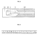
- Fig. 8 is a plan view of a so-called round up type male spline section in which the end portion opposite to the shaft end (left-hand side in the drawing) of a valley section 100 is connected to the outer peripheral surface (smooth portion) 101 of a male member via a diameter-expanded section 102 whose outer diameter is gradually increased.
- Fatigue fracture of a spline section of this type usually occurs near the connection between the valley section 100 and the diameter-expanded section 102 or in the diameter-expanded section 102.
- there are two modes in which a crack is generated one due to tensile stress concentrated on portion A, and one due to shear stress concentrated on portion B.
- the Vickers hardness is less than 700
- shear stress is predominant.
- tensile stress is predominant.
- Patent Document 1 discloses a technology for mitigating stress concentration by blunting the boundary between a diameter-expanded section and a tooth surface.
- Patent Document 2 discloses a strength enhancing technology according to which, instead of arranging one diameter-expanded section as usual, two or more diameter-expanded sections are arranged side by side.
- Patent Document 1 admittedly proves to be effective in mitigating tensile stress concentration, it is still inadequate for mitigating shear stress concentration.
- Patent Document 2 allows mitigation of shear stress concentration, it is insufficient from the viewpoint of mitigating tensile stress concentration. In this way, while there exists a technology helping to mitigate one of the two types of stress causing crack generation, no technology is available which helps to mitigate both, which means there is still room for improvement from the viewpoint of realizing a further improvement in terms of fatigue strength.
- the inventors of the present invention produced a specimen which had a notch in a parallel section, subjecting it to rotational bending fatigue test and torsional fatigue test to obtain the relationship between stress concentration coefficient and fatigue strength.
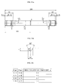
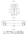
- Fig. 10a illustrates a specimen for rotational bending fatigue test
- Fig. 11a illustrates a specimen for torsional fatigue test.
- the radius of curvature of the notch tip 0.10, 0.15, 0.25, 0.50, and 1.40, respectively setting the stress concentration coefficient ⁇ of each of them to 3.5, 3.0, 2.5, 2.0, and 1.5 (see Fig. 10c ).
- the rotational bending fatigue test was conducted by the Ono rotational bending fatigue testing machine at room temperature in atmospheric air at a load frequency of 50 Hz.
- the stress amplitude is a nominal stress amplitude not dependent on the notch level, and means the amplitude of the maximum tensile stress operating on the surface when the same bending moment as that in the fatigue test is imparted to a smooth round bar having a notch bottom diameter of ( ⁇ 6.5 mm).
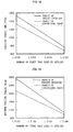
- Fig. 12 illustrates the relationship between the stress concentration coefficient ⁇ ⁇ and the fatigue limit obtained in the above-mentioned rotational bending fatigue test. As illustrated in the drawing, the fatigue strength increased as ⁇ ⁇ decreased. However, as indicated by the dashed lines in the drawing, it was found out that the gradient of the fatigue curve is large when ⁇ ⁇ ⁇ .7, which more conspicuously indicates an improvement in terms of fatigue strength when ⁇ ⁇ is reduced.
- the stress amplitude refers to a nominal stress amplitude not dependent on the notch level, and means the amplitude of the maximum shear stress operating on the surface when the same torsional torque as that in the fatigue test is imparted to a smooth round bar having a notch bottom diameter of ( ⁇ 17 mm).
- Fig. 13 illustrates the relationship between the stress concentration coefficient ⁇ ⁇ and the fatigue strength at 10 5 times obtained in the reversed torsional fatigue test. As illustrated in the drawing, the fatigue strength increased as ⁇ ⁇ decreased. However, as indicated by the dashed lines in the drawing, it was found out that the gradient of the fatigue curve is large when ⁇ ⁇ ⁇ 2.1, which more conspicuously indicates an improvement in terms of fatigue strength when ⁇ ⁇ is reduced.
- ⁇ 0 16 ⁇ T ⁇ d 0 / ⁇ ⁇ d 0 4 - d i 4
- the inventors of the present invention effected various configuration tunings on the diameter-expanded section and found out that, by providing a rounded section on both sides in the circumferential direction of the diameter-expanded section of the male spline section and gradually increasing the radius of curvature of the rounded sections toward the side opposite to the shaft end, it is possible to satisfy the conditions: ⁇ 1max ⁇ 2.7 ⁇ 0 , and ⁇ ⁇ zmax ⁇ 2.1 ⁇ 0 .
- the reversed torsional fatigue test was conducted in four levels of torsion torque amplitude ranging from 850 to 1300 Nm, and, in the pulsating torsional fatigue test, maximum torsional torque in four levels ranging from 1250 to 2000 Nm was imparted.
- Fig. 18 illustrates a T/N chart obtained from the reversed torsional fatigue test
- Fig. 19 illustrates a T/N chart obtained from the pulsating torsional fatigue test.
- the present invention is characterized by the following:
- rounded sections are provided on both circumferential sides of the diameter-expanded section of the male spline section, with a radius of curvature of the rounded sections being gradually increased toward one axial end.
- ⁇ 0 16 ⁇ T ⁇ d 0 / ⁇ ⁇ d 0 4 - d i 4
- the male spline section of a power transmission shaft be hardened by, for example, induction hardening. Further, by effecting shot peening on the male spline section of the power transmission shaft, it is possible to further enhance the fatigue strength of the male spline section.
- a plunging type constant velocity universal joint is characterized by including: an outer joint member having in an outer periphery thereof a stem portion having the male spline section; an inner joint member accommodated in an inner diameter portion of the outer joint member; and a torque transmission member provided between the outer joint member and the inner joint member and adapted to transmit torque.
- a fixed type constant velocity universal joint is characterized by including: an outer joint member having a stem portion and a mouth portion, the male spline section, which being formed in an outer periphery of the stem portion, a track groove, which being formed in an inner periphery of the mouth portion; an inner joint member having a track groove in an outer periphery thereof; torque transmission balls arranged in a ball track formed by the track groove of the outer joint member and the track groove of the inner joint member; and a cage retaining the torque transmission balls at equal circumferential intervals.
- a power transmission spline according to the present invention is characterized by including: the male spline section provided in an outer periphery of a male member; and a female spline section provided in an inner periphery of a female member and fit-engaged with the male spline section.
- Fig. 1 is a partial sectional view of a power transmission shaft 2 serving as a male member.
- the power transmission shaft 2 illustrated in the drawing is solid, and is made of a medium carbon steel of a carbon amount of approximately 0.30 to 0.60 wt%.
- the carbon amount is less than 0.30 wt%, stable high hardness cannot be attained even if induction hardening is treated.
- the carbon amount exceeds 0.60 wt%, the material hardness increases, resulting in marked deterioration in workability for rolling or the like.
- a stab shaft see Fig.
- the S amount in the steel it is desirable for the S amount in the steel to be within the range of 0.002 to 0.008 wt%.
- the reason for setting the upper limit value of the S amount to 0.008 wt% is to maintain satisfactory weldability and friction pressure welding property.
- the reason for setting the lower limit value to 0.002 wt% is that it is difficult to set it to a level lower than that and that there is little meaning in doing so.
- a male spline section Sm is formed in the outer periphery of the axial ends of the power transmission shaft 2.
- the power transmission shaft 2 and the female member F are connected together so as to allow torque transmission.
- the inner end portion at the end on the side opposite to the axial end (left-hand side in Fig. 3 ) of the female member F is held in contact with a shoulder portion 24 in the outer periphery of the power transmission shaft 2, and the inner end portion of the axial end side (right-hand side in Fig. 3 ) is locked, for example, by a snap ring 8 (see Fig. 29 ), whereby the female member F is fixed in position in the axial direction with respect to the power transmission shaft 2.
- the male spline section Sm of the power transmission shaft 2 has axially extending valley sections 21 and crest sections 22 alternately in the circumferential direction.
- the male spline section Sm of this embodiment is of a so-called round up type formed by rolling, each valley section 21 includes a straight portion 21a of the same dimension in the axial direction and a diameter-expanded section 21b formed at the axially opposite end thereof.
- each crest section 22 includes a straight portion 22a of the same dimension in the axial direction, and a diameter-reduced section 22b formed at the axially opposite end thereof.
- the start ends of the diameter-expanded section 21b and the diameter-reduced section 22b are at the same position in the axial direction, and the terminal end thereof are also at the same position in the axial direction. It is also possible to form the male spline section Sm by cold forging. In this case, the diameter-reduced sections 22b of the crest sections 22 are not formed, and the axially opposite end side of the crest sections 22 as a whole is of the same outer diameter dimension. Heat treatment such as induction hardening is treated on the male spline section Sm after the formation. Further, shot peening is treated thereon as needed.
- the valley section 31, which is formed in an inner periphery of the female member F, of the female spline section Sf is formed to extend in the same diameter dimension to the end on the axially opposite side.
- the crest section 32 has a small diameter portion 32a, a large diameter portion 32b, and a rising portion 32c between the small diameter portion 32a and the large diameter portion 32b.
- the inner diameter dimension of the large diameter portion 32b is smaller than the outer diameter dimension of the crest section 22 of the male spline section Sm (outer diameter dimension of the straight portion 22a), and larger than the outer diameter dimension of a smooth portion 25 of the power transmission shaft 2 formed on the axially opposite end side of the male spline section Sm.
- the tooth surface 23 of the male spline section Sm and the tooth surface (not shown) of the female spline section Sf are brought into firm press contact with each other.
- the fit-engagement portion between the two tooth surfaces at this time extends also to the outer side region of the diameter-expanded section 21b.
- Fig. 3 illustrates the case in which the axial sections of the diameter-expanded section 21b and the diameter-reduced section 22b are both formed in a straight tapered configuration, it is also possible to form the axial sections of both in a curved configuration. It is also possible to combine straight and curved configurations.
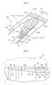
- the diameter-expanded section 21b of the male spline section Sm includes rounded sections 21b1 (indicated by the dotted pattern) formed on both circumferential sides thereof and a flat section 21b2 formed between the rounded sections 21b1.
- the rounded sections 21b1 have an arcuate radial sectional configuration, and both circumferential sides thereof are smoothly connected to the tooth surface 23 and the flat section 21b2.
- Fig. 4 is a plan view illustrating the portion around the diameter-expanded section 21b of the male spline Sm
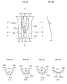
- Figs. 5a through 5d are sectional views taken along the lines A-A, B-B, C-C, and D-D.
- the radius of curvature R A of the rounded section connecting the straight section 21a of the valley section 21 and the tooth surface 23 is fixed up to the boundary portion leading to the diameter-expanded section 21b.
- Figs. 5a the radius of curvature R A of the rounded section connecting the straight section 21a of the valley section 21 and the tooth surface 23 is fixed up to the boundary portion leading to the diameter-expanded section 21b.
- the radius of curvature of the rounded sections 21b1 is larger than the radius of curvature R A of the boundary portion, and increases gradually toward the axially opposite end side (R A ⁇ R B ⁇ R C ⁇ R D ). Further, as illustrated in Fig. 4 , up to the positions where the boundary lines of the rounded sections 21b1 cross the ridges of the crest sections and where the tooth surface 23 ceases to exist, the circumferential width dimension of the rounded sections 21b1 gradually increases toward the axially opposite end side (upwards as seen in the drawing). After the increase, the width dimension is gradually reduced. The circumferential width dimension of the flat section 21b2 also increases gradually toward the axially opposite end side.
- symbol L indicates a coordinate in the direction of a line passing the center of the radius of curvature of each rounded section 21b1 of the diameter-expanded section 21b.
- the increase ratio of the radius of curvature of the rounded section 21b1 is expressed by the formula dR/dL.
- dR/dL is set to 0.18.
- symbol ⁇ indicates the inclination angle of a straight line connecting the small diameter end and the large diameter end of the axial section of the diameter-expanded section 21b. In this embodiment, the angle ⁇ is set to 8.3°.
- Figs. 14 through 16 illustrate the male spline section Sm ' as disclosed in Patent Document 1 ( JP 2005-147367 A ), that is, the male spline section Sm' in which the rounded sections 21b1' are formed at the boundaries between the diameter-expanded section 21b' and the tooth surface 23' and in which the radius of curvature of the rounded sections 21b1' is fixed over the entire axial length (In Figs. 14 through 16 , the portions corresponding to those illustrated in Figs. 2 through 4 are indicated by the same reference numerals with (') affixed thereto).
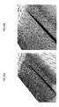
- This FEM analysis is a three-dimensional linear elastic analysis, and "I-deas Ver. 10" was used as the analysis software.
- the analysis model is a linear elastic body including one valley section 21, 21' of the male spline section Sm, Sm', and the model length is 100 mm.
- Fig. 21 illustrates a mesh added to this analysis model.
- Each element is a tetrahedral secondary element.
- the total number of elements is approximately 200,000, and the total number of contacts is approximately 300,000.
- the element length is 0.2 mm or less (the minimum element length is 0.05 mm) in the principal portion P (portion including the male spline section Sm, Sm'), and is 0.5 mm in the portion other than the principal portion P.
- Figs. 22 are enlarged views of the meshes of the principal portion P
- portion (a) illustrates a product according to the present invention corresponding to Fig. 2
- portion (b) illustrates a product according to the prior art corresponding to Fig. 14
- a Rigid element was prepared at the axially opposite end side end surface M of the analysis model, and torque T was loaded on the central axis O of the end surface M.
- the model used is a 1/tooth-number model
- the loaded torque is 1/tooth-number of the actual torque.
- Fig. 23 a Rigid element was prepared at the axially opposite end side end surface M of the analysis model, and torque T was loaded on the central axis O of the end surface M.
- the model used is a 1/tooth-number model
- the loaded torque is 1/tooth-number of the actual torque.
- the analysis model is of a configuration in axial symmetry with respect to a radial axis passing the center of the valley section 21, with all the contacts of both side surfaces W in the circumferential direction being in periodical symmetry.
- Fig. 25 in the surface of the analysis model to be brought into contact with the mating member (indicated by the dotted pattern), displacement in the direction of the normal thereof is constrained.
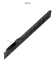
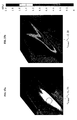
- Figs. 26 illustrate the analysis result of the maximum principal stress ⁇ 1
- Figs. 27 illustrate the analysis result of the axial shear stress ⁇ ⁇ z
- portion (a) illustrates a model according to the present invention
- ⁇ ⁇ zmax / ⁇ 0 2.28
- ⁇ ⁇ zmax / ⁇ 0 1.74
- the stress concentration mitigating effect is conspicuous, and hence the present invention, in which ⁇ ⁇ zmax / ⁇ 0 ⁇ 2.1, helps to achieve a substantial improvement in terms of fatigue strength with respect to shear stress over the prior art.
- the present invention it is possible to attain with the male spline section Sm a high stress concentration mitigating effect with respect to both tensile stress and shear stress.
- the maximum shear stress ⁇ ⁇ zmax is generated in the starting point center line of each diameter-expanded section 21b'.
- the maximum shear stress is generated in the same portion in both the normal and reverse rotation when the power transmission shaft 2 transmits torque in both the normal and reverse directions, and hence fatigue fracture progresses so much the easier.
- the maximum shear stress ⁇ ⁇ zmax is generated in both rounded sections 21b1, which are on the axially opposite end side of the starting point of the diameter-expanded section 21b.
- the present invention is especially suitable for uses in which the torque transmitting direction is frequently switched, for example, uses in which the torque transmitting direction is reversed according as a vehicle advances or retreats.
- the above-mentioned diameter-expanded section having the rounded sections 21b1 can be formed simultaneously with the teeth of the male spline section Sm by forming, in a rolling rack used in component rolling, a formed portion of a configuration corresponding to the diameter-expanded section 21b. Also in the case in which the male spline section is formed by cold forging through press working, a formed portion corresponding to the configuration of the diameter-expanded section 21b is previously formed on the press working die, whereby it is possible to form the rounded sections 21b1 simultaneously with the teeth of the male spline section Sm.
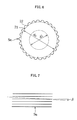
- Fig. 7 illustrates another embodiment of the present invention.
- the teeth of one of the male spline section Sm or the female spline section Sf has a torsional angle ⁇ with respect to the axial direction, which is effective in eliminating backlash between the spline sections Sm and Sf after the fit-engagement.
- the torsional angle ⁇ is provided, the inter-tooth-surface contact pressure on the torque transmission side increases, and, with that, the tensile stress and shear stress concentrated on the diameter-expanded section also increase, resulting in deterioration in fatigue strength. From this viewpoint, the torsional angle ⁇ has been substantially limited to 15' in the prior art.
- a stab shaft 200 has at one end thereof a male spline section Sm for connection to the inner joint member of a constant velocity universal joint or the like, and, at the other end, a flange portion 202 for the pressure welding or welding of a steel pipe 203.
- the present invention to the male spline section Sm of the stab shaft 200, it is possible to improve the fatigue strength of the stab shaft 200.
- the stab shaft illustrated in the drawing is a solid one, it may also be formed as a hollow one.
- the present invention lies in the mitigation of stress concentration coefficient through an improvement in configuration, and the above-mentioned embodiments should not be construed restrictively, and the present invention is also applicable to power transmission shafts made of various materials.
- the power transmission shaft may also be one made of steel which is not hardened through quenching.
- the power transmission shaft may also be one made of non-iron metal, ceramic material, resin material or the like.
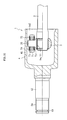
- Fig. 29 illustrates a constant velocity universal joint 1 connected to a solid power transmission shaft 2 as described above.
- the constant velocity universal joint 1 mainly includes an inner joint member 3 fixed to the power transmission shaft 2, an outer joint member 4 arranged on the outer side of the inner joint member 3, and balls 5 as torque transmission members for transmitting torque between the inner joint member 3 and the outer joint member 4.
- the outer joint member 4 has a cup-shaped mouth member 41 and a stem portion 42 as integral or separate components.
- the constant velocity universal joint illustrated in the drawing is a fixed type called the zepper type.
- the balls 5 are arranged in a ball track formed by a track groove 3a1 formed in an outer spherical surface 3a of the inner joint member 3 and a track groove 4a1 formed in an inner spherical surface 4a of the outer joint member 4a, with a plurality of balls 5 arranged at equal circumferential intervals being retained by a cage 7.
- the center of curvature O1 of the track groove of the outer joint member 4 and the center of curvature 02 of the track groove of the inner joint member 3 are axially offset in opposite directions by the same distance with respect to the joint center O. That is, the center of curvature O1 of the track groove 4a1 of the outer joint member 4 is on the opening side, and the center of curvature 02 of the track groove 3a1 of the inner joint member 3 is on the depth side.
- each of the track grooves 3a and 4a is shallow on the mouth portion 41 bottom side (depth side) and deep on the mouth portion 41 opening side with respect to the center in the axial direction, forming a wedge-shaped ball track in which the radial distance gradually increases from the bottom side toward the opening side.
- the outer joint member 4 is made of medium carbon steel whose carbon content is approximately 0.35 to 0.60 wt%.
- the carbon content is less than 0.35 wt%, a stable high hardness cannot be attained even if induction hardening is treated, and when the carbon content exceeds 0.60 wt%, the material hardness increases, and resulting in deterioration in workability when forming the male spline section Sm described below by rolling or the like.
- the inner joint member 3 constitutes the female member F illustrated in Fig. 3 .
- the male spline section Sm of the power transmission shaft 2 With the female spline section Sf formed in the inner periphery of the inner joint member 3, power transmission is effected between the inner joint member 3 and the power transmission shaft 2.
- the male spline section Sm of the power transmission shaft 2 By forming the male spline section Sm of the power transmission shaft 2 in the configuration as illustrated in Figs. 2 through 5 , it is possible to improve the fatigue strength of the power transmission shaft 2.
- the male spline section Sm of this embodiment is formed, as illustrated in the drawing, in the outer periphery of a stem portion 42 which is provided integrally or separately with the outer joint member 4.
- the outer joint member 4 and the female member F are connected together so as to allow torque transmission.
- the end surface of the female member F on the axially opposite end side left-hand side in Fig.
- the present invention is also applicable to a fixed type constant velocity universal joint of the construction as illustrated in Fig. 29 , in which both the opening side end portion of the track groove 4a1 of the outer joint member 4 and the depth side end portion of the track groove 3a1 of the inner joint member 3 are formed in a configuration extending straight in the axial direction (undercut free type constant velocity universal joint).
- the constant velocity universal joint 1 is not restricted to the one illustrated in the drawings, and it is also possible to use some other fixed type constant velocity universal joint, or a plunging type constant velocity universal joint such as a tripod universal joint.
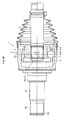
- Fig. 31 illustrates a tripod constant velocity universal joint 1 as an example of the plunging type constant velocity universal joint.
- the constant velocity universal joint 1 mainly includes an inner joint member 3 connected to a power transmission shaft 2, an outer joint member 4 arranged on the outer diameter side of the inner joint member 3, and a roller cassette 70 as a torque transmission member for transmitting torque between the inner joint member 3 and the outer joint member 4.
- the outer joint member 4 has a cup-shaped mouth portion 41 and a shaft-shaped stem portion 42 which are provided integrally or separately with each other, and has, at a circumferential position of division into three equal parts of the inner periphery of the mouth portion 41, an axially extending track groove 4a2.
- Leg shafts 35 protrude from three circumferential positions of the inner joint member 3.
- the roller cassette 70 illustrated in Fig. 31 is of the double roller type.
- the double roller type cassette is provided, for example, with a roller (outer roller) 71 rolling in a track groove 4a2, a ring (inner roller) 72 fitted onto the leg shaft 35, and a plurality of needle rollers 73 provided between the outer roller and the inner roller.
- the cross-section of the leg shaft 35 is elliptical, and forms a gap between itself and the inner peripheral surface of the ring 72 in the longitudinal direction of the track groove 4a2, and is in contact with the inner peripheral surface of the ring 72 in the track groove width direction orthogonal to the longitudinal direction.
- a washer 75 for preventing detachment of the needle rollers 73 is attached to an annular grove formed in the inner peripheral surface of an end portion of the roller 71.
- the roller 71 is rockable with respect to the axis of the leg shaft 35.
- the roller cassette 70 may be formed as a single roller type one.
- the outer joint member 4 is made of a medium carbon steel of a carbon content of approximately 0.35 to 0.60 wt%.
- the carbon content is less than 0.35 wt%, it is impossible to attain a stable, high hardness even if induction hardening is treated, and when the carbon content exceeds 0.60 wt%, the material hardness increases, and the workability when forming the male spline section Sm described below by rolling or the like deteriorates.
- the male spline section Sm is formed in the outer periphery of the stem portion 42 of the outer joint member 4.
- a female spline section Sf formed in the inner periphery of the female member F as illustrated in Fig. 3 .
- the female member F is fixed in position in the axial direction with respect to the outer joint member 4, for example, by holding the inner end portion on the axially opposite side thereof (left-hand side in Fig. 3 ) in contact with a shoulder portion 24 in the outer periphery of the outer joint member 4 and locking the inner end portion of the axial end side (right-hand side in Fig.
- the male spline section Sm of the above-mentioned embodiment may also be formed in the outer periphery of the power transmission shaft 2 connected to the inner joint member 3 of the constant velocity universal joint 1.
- the female spline section Sf is formed in the inner periphery of the inner joint member 3, and torque transmission is effected between the power transmission shaft 2 and the inner joint member 3 through fit-engagement of the two spline sections.
- the male spline section Sm described above may be formed not only in a tripod constant velocity universal joint but also in some other plunging type constant velocity universal joint, such as the double offset type constant velocity universal joint 1 illustrated in Fig. 32 .
- the constant velocity universal joint 1 mainly includes the outer joint member 4, the inner joint member 3 mounted to one end of the power transmission shaft 2, torque transmission balls 7 as the torque transmission member arranged between the inner joint member 3 and the outer joint member 4, and a retainer 5 provided between the inner joint member 3 and the outer joint member 4 and supporting the torque transmission balls 7.
- the outer joint member 4 has the cylindrical mouth portion 41 and the stem portion 42 which are provided integrally or separately.
- the inner peripheral surface of the mouth portion 41 there are formed a plurality of linear track grooves 4a2 parallel to the axis thereof and arranged at equal circumferential intervals
- the outer peripheral surface of the inner joint member 3 there are formed a plurality of linear track grooves 3a2 parallel to the axis in correspondence with the track grooves 4a2 of the outer joint member 4 and arranged at equal circumferential intervals.
- the outer peripheral surface of the inner joint member 3 is partially spherical, and the power transmission shaft 2 is connected with the inner periphery thereof.
- the retainer 5 is guided by the partially spherical outer peripheral surface of the inner joint member 3 and the inner peripheral surface of the outer joint member 4 while being in contact therewith, and the inner peripheral surface and the outer peripheral surface thereof are formed as partially spherical surfaces having centers of curvature O1 and 02 offset by the same distance in the axial direction with respect to the joint center surface including the joint center O.
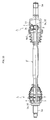
- Fig. 33 is a sectional view of a drive shaft having a power transmission shaft 2'.
- the fixed type constant velocity universal joint 1 (J1) is attached to the out-board side (outer side in the vehicle width direction when mounted in a vehicle) end portion
- the plunging type constant velocity universal joint J2 as illustrated in Figs. 31 and 32 is attached to the in-board side (side nearer to the center in the vehicle width direction when mounted in the vehicle) end portion.
- a male spline section Sm of the configuration as illustrated in Figs. 2 through 5 , and the male spline sections Sm are fit-engaged with the female spline sections Sf of the inner joint member 3, whereby the constant velocity universal joints J1 and J2 are connected to the shaft ends so as to allow torque transmission.
- the power transmission shaft 2' of this embodiment is formed as a hollow shaft.
- the reference stress ⁇ 0 can be obtained by the following equation:
- ⁇ 0 16 ⁇ Td 0 / ⁇ ⁇ d 0 4 - d i 4
Landscapes
- Engineering & Computer Science (AREA)
- General Engineering & Computer Science (AREA)
- Mechanical Engineering (AREA)
- Ocean & Marine Engineering (AREA)
- Shafts, Cranks, Connecting Bars, And Related Bearings (AREA)
Applications Claiming Priority (5)
| Application Number | Priority Date | Filing Date | Title |
|---|---|---|---|
| JP2006245905A JP2008064297A (ja) | 2006-09-11 | 2006-09-11 | 動力伝達スプライン |
| JP2006245896A JP2008064295A (ja) | 2006-09-11 | 2006-09-11 | 摺動型等速自在継手 |
| JP2006245884A JP5259064B2 (ja) | 2006-09-11 | 2006-09-11 | 動力伝達シャフト |
| JP2006245894A JP2008064294A (ja) | 2006-09-11 | 2006-09-11 | 固定型等速自在継手 |
| PCT/JP2007/067305 WO2008032626A1 (en) | 2006-09-11 | 2007-09-05 | Power transmission spline |
Publications (2)
| Publication Number | Publication Date |
|---|---|
| EP2060813A1 true EP2060813A1 (de) | 2009-05-20 |
| EP2060813A4 EP2060813A4 (de) | 2011-01-12 |
Family
ID=39183687
Family Applications (1)
| Application Number | Title | Priority Date | Filing Date |
|---|---|---|---|
| EP07806748A Withdrawn EP2060813A4 (de) | 2006-09-11 | 2007-09-05 | Keilverzahnung zur kraftübertragung |
Country Status (3)
| Country | Link |
|---|---|
| US (1) | US8079912B2 (de) |
| EP (1) | EP2060813A4 (de) |
| WO (1) | WO2008032626A1 (de) |
Cited By (1)
| Publication number | Priority date | Publication date | Assignee | Title |
|---|---|---|---|---|
| EP2980433A4 (de) * | 2013-03-25 | 2017-03-01 | NTN Corporation | Triebkraftübertragende welle und keilbearbeitungsverfahren |
Families Citing this family (11)
| Publication number | Priority date | Publication date | Assignee | Title |
|---|---|---|---|---|
| JP2008196592A (ja) * | 2007-02-13 | 2008-08-28 | Ntn Corp | 動力伝達シャフト |
| FR2989440B1 (fr) * | 2012-04-13 | 2014-05-23 | Snecma | Accouplement d'arbres par cannelures a profil evolutif |
| DE102012222627B4 (de) * | 2012-12-10 | 2021-11-04 | Robert Bosch Gmbh | Rohrförmige Vorrichtung zur Verbindung mit einer Welle |
| US9670951B2 (en) | 2014-04-08 | 2017-06-06 | A.A.M International S.A.R.L. | Variable-wall light-weight axle shaft with an integral flange member and method for making the same |
| US20150367681A1 (en) * | 2014-06-18 | 2015-12-24 | American Axle & Manufacturing, Inc. | Hollow axle shaft for a vehicle and a method of manufacturing the same |
| US10072712B2 (en) * | 2015-06-18 | 2018-09-11 | GM Global Technology Operations LLC | Shaft coupling arrangement |
| US10385929B2 (en) * | 2016-01-06 | 2019-08-20 | Boninfante Friction, Inc. | Vehicle input shafts |
| CN106407558B (zh) * | 2016-09-19 | 2020-01-21 | 中国航空工业集团公司沈阳飞机设计研究所 | 一种圆柱形构件内径的计算方法 |
| US10975915B2 (en) * | 2018-01-08 | 2021-04-13 | Raytheon Technologies Corporation | Assembly alignment handling damage tolerant spline |
| US11052937B2 (en) * | 2018-01-19 | 2021-07-06 | Steering Solutions Ip Holding Corporation | Splined component assembly and method |
| US20220290723A1 (en) * | 2021-03-14 | 2022-09-15 | Textron Innovations Inc. | Drive splines with friction-reducing coating |
Family Cites Families (11)
| Publication number | Priority date | Publication date | Assignee | Title |
|---|---|---|---|---|
| DE19722917C1 (de) | 1997-05-31 | 1998-08-13 | Gkn Automotive Ag | Wellen-Naben-Einheit |
| WO2000005514A1 (en) * | 1998-07-22 | 2000-02-03 | Ntn Corporation | Power transmission mechanism |
| US6484384B1 (en) | 1998-12-31 | 2002-11-26 | Spicer Driveshaft, Inc. | Method of manufacturing an axially collapsible driveshaft assembly |
| US6672966B2 (en) * | 2001-07-13 | 2004-01-06 | Honeywell International Inc. | Curvic coupling fatigue life enhancement through unique compound root fillet design |
| EP1653099B1 (de) * | 2003-08-07 | 2014-12-31 | Honda Motor Co., Ltd. | Kraftübertragungsmechanismus für welle und nabe |
| JP2005069475A (ja) | 2003-08-07 | 2005-03-17 | Honda Motor Co Ltd | シャフト及びハブの動力伝達機構 |
| US8043023B2 (en) * | 2003-08-07 | 2011-10-25 | Honda Motor Co., Ltd. | Power transmission mechanism of shaft and hub |
| JP2005146313A (ja) * | 2003-11-12 | 2005-06-09 | Ntn Corp | 動力伝達軸 |
| JP2005147367A (ja) * | 2003-11-19 | 2005-06-09 | Ntn Corp | 動力伝達軸 |
| JP2006083963A (ja) | 2004-09-16 | 2006-03-30 | Ntn Corp | 中空状動力伝達シャフト |
| JP2008064291A (ja) | 2006-09-11 | 2008-03-21 | Ntn Corp | 鋼球転動構造及び等速自在継手 |
-
2007
- 2007-09-05 US US12/310,841 patent/US8079912B2/en not_active Expired - Fee Related
- 2007-09-05 WO PCT/JP2007/067305 patent/WO2008032626A1/ja not_active Ceased
- 2007-09-05 EP EP07806748A patent/EP2060813A4/de not_active Withdrawn
Cited By (2)
| Publication number | Priority date | Publication date | Assignee | Title |
|---|---|---|---|---|
| EP2980433A4 (de) * | 2013-03-25 | 2017-03-01 | NTN Corporation | Triebkraftübertragende welle und keilbearbeitungsverfahren |
| US10352365B2 (en) | 2013-03-25 | 2019-07-16 | Ntn Corporation | Power transmission shaft and spline-processing method |
Also Published As
| Publication number | Publication date |
|---|---|
| US8079912B2 (en) | 2011-12-20 |
| EP2060813A4 (de) | 2011-01-12 |
| US20090270187A1 (en) | 2009-10-29 |
| WO2008032626A1 (en) | 2008-03-20 |
Similar Documents
| Publication | Publication Date | Title |
|---|---|---|
| EP2060813A1 (de) | Keilverzahnung zur kraftübertragung | |
| US6319337B1 (en) | Power transmission shaft | |
| US20010021671A1 (en) | Constant velocity joint and rolling bearing unit for wheel | |
| US20190101165A1 (en) | Tripod type constant velocity universal joint and heat treatment method for a tripod member | |
| JP5917249B2 (ja) | 等速自在継手の内方部材およびその製造方法 | |
| JP4271301B2 (ja) | 動力伝達機構 | |
| US7651400B2 (en) | Constant velocity universal joint and inner member thereof | |
| US20250243909A1 (en) | Tripod-type constant-velocity universal joint | |
| EP2749783B1 (de) | Gleichlaufgelenk und herstellungsverfahren dafür | |
| JP7680914B2 (ja) | トリポード型等速自在継手 | |
| JP5160316B2 (ja) | 等速ジョイント用ボール及びその製造方法 | |
| JP4957362B2 (ja) | Cvt用シャフト及びその製造方法 | |
| JP2008095845A (ja) | 動力伝達スプライン | |
| JP5259064B2 (ja) | 動力伝達シャフト | |
| JP2008095805A (ja) | 動力伝達シャフト | |
| JP2008196592A (ja) | 動力伝達シャフト | |
| JP2008240968A (ja) | 動力伝達シャフト | |
| JP2008064294A (ja) | 固定型等速自在継手 | |
| JP2008196013A (ja) | 動力伝達シャフト | |
| JP2008256203A (ja) | 動力伝達シャフト | |
| JP2008064297A (ja) | 動力伝達スプライン | |
| JP2008128407A (ja) | 固定型等速自在継手 | |
| EP4317732A1 (de) | Tripode-gleichlaufgelenk | |
| JP2008075826A (ja) | 中空動力伝達シャフト | |
| JP2008286315A (ja) | 動力伝達シャフト |
Legal Events
| Date | Code | Title | Description |
|---|---|---|---|
| PUAI | Public reference made under article 153(3) epc to a published international application that has entered the european phase |
Free format text: ORIGINAL CODE: 0009012 |
|
| 17P | Request for examination filed |
Effective date: 20090313 |
|
| AK | Designated contracting states |
Kind code of ref document: A1 Designated state(s): AT BE BG CH CY CZ DE DK EE ES FI FR GB GR HU IE IS IT LI LT LU LV MC MT NL PL PT RO SE SI SK TR |
|
| AX | Request for extension of the european patent |
Extension state: AL BA HR MK RS |
|
| A4 | Supplementary search report drawn up and despatched |
Effective date: 20101210 |
|
| DAX | Request for extension of the european patent (deleted) | ||
| 17Q | First examination report despatched |
Effective date: 20130717 |
|
| STAA | Information on the status of an ep patent application or granted ep patent |
Free format text: STATUS: THE APPLICATION IS DEEMED TO BE WITHDRAWN |
|
| 18D | Application deemed to be withdrawn |
Effective date: 20160914 |