EP2060823A2 - Couche hydraulique - Google Patents
Couche hydraulique Download PDFInfo
- Publication number
- EP2060823A2 EP2060823A2 EP08019669A EP08019669A EP2060823A2 EP 2060823 A2 EP2060823 A2 EP 2060823A2 EP 08019669 A EP08019669 A EP 08019669A EP 08019669 A EP08019669 A EP 08019669A EP 2060823 A2 EP2060823 A2 EP 2060823A2
- Authority
- EP
- European Patent Office
- Prior art keywords
- membrane
- mount according
- hydraulic mount
- compensation chamber
- hydraulic
- Prior art date
- Legal status (The legal status is an assumption and is not a legal conclusion. Google has not performed a legal analysis and makes no representation as to the accuracy of the status listed.)
- Granted
Links
- 239000012528 membrane Substances 0.000 claims abstract description 89
- 239000013536 elastomeric material Substances 0.000 claims description 12
- 239000000463 material Substances 0.000 claims description 4
- 210000004379 membrane Anatomy 0.000 description 85
- 238000013016 damping Methods 0.000 description 9
- 239000012530 fluid Substances 0.000 description 9
- 239000011324 bead Substances 0.000 description 7
- 230000015572 biosynthetic process Effects 0.000 description 2
- 230000000694 effects Effects 0.000 description 2
- 230000001939 inductive effect Effects 0.000 description 2
- 238000004519 manufacturing process Methods 0.000 description 2
- 230000002238 attenuated effect Effects 0.000 description 1
- 230000004888 barrier function Effects 0.000 description 1
- 230000001419 dependent effect Effects 0.000 description 1
- 230000002093 peripheral effect Effects 0.000 description 1
- 230000000979 retarding effect Effects 0.000 description 1
- 238000007789 sealing Methods 0.000 description 1
- 230000035939 shock Effects 0.000 description 1
Images


Classifications
-
- F—MECHANICAL ENGINEERING; LIGHTING; HEATING; WEAPONS; BLASTING
- F16—ENGINEERING ELEMENTS AND UNITS; GENERAL MEASURES FOR PRODUCING AND MAINTAINING EFFECTIVE FUNCTIONING OF MACHINES OR INSTALLATIONS; THERMAL INSULATION IN GENERAL
- F16F—SPRINGS; SHOCK-ABSORBERS; MEANS FOR DAMPING VIBRATION
- F16F13/00—Units comprising springs of the non-fluid type as well as vibration-dampers, shock-absorbers, or fluid springs
- F16F13/04—Units comprising springs of the non-fluid type as well as vibration-dampers, shock-absorbers, or fluid springs comprising both a plastics spring and a damper, e.g. a friction damper
- F16F13/06—Units comprising springs of the non-fluid type as well as vibration-dampers, shock-absorbers, or fluid springs comprising both a plastics spring and a damper, e.g. a friction damper the damper being a fluid damper, e.g. the plastics spring not forming a part of the wall of the fluid chamber of the damper
- F16F13/08—Units comprising springs of the non-fluid type as well as vibration-dampers, shock-absorbers, or fluid springs comprising both a plastics spring and a damper, e.g. a friction damper the damper being a fluid damper, e.g. the plastics spring not forming a part of the wall of the fluid chamber of the damper the plastics spring forming at least a part of the wall of the fluid chamber of the damper
- F16F13/10—Units comprising springs of the non-fluid type as well as vibration-dampers, shock-absorbers, or fluid springs comprising both a plastics spring and a damper, e.g. a friction damper the damper being a fluid damper, e.g. the plastics spring not forming a part of the wall of the fluid chamber of the damper the plastics spring forming at least a part of the wall of the fluid chamber of the damper the wall being at least in part formed by a flexible membrane or the like
- F16F13/105—Units comprising springs of the non-fluid type as well as vibration-dampers, shock-absorbers, or fluid springs comprising both a plastics spring and a damper, e.g. a friction damper the damper being a fluid damper, e.g. the plastics spring not forming a part of the wall of the fluid chamber of the damper the plastics spring forming at least a part of the wall of the fluid chamber of the damper the wall being at least in part formed by a flexible membrane or the like characterised by features of partitions between two working chambers
- F16F13/107—Passage design between working chambers
-
- F—MECHANICAL ENGINEERING; LIGHTING; HEATING; WEAPONS; BLASTING
- F16—ENGINEERING ELEMENTS AND UNITS; GENERAL MEASURES FOR PRODUCING AND MAINTAINING EFFECTIVE FUNCTIONING OF MACHINES OR INSTALLATIONS; THERMAL INSULATION IN GENERAL
- F16F—SPRINGS; SHOCK-ABSORBERS; MEANS FOR DAMPING VIBRATION
- F16F13/00—Units comprising springs of the non-fluid type as well as vibration-dampers, shock-absorbers, or fluid springs
- F16F13/04—Units comprising springs of the non-fluid type as well as vibration-dampers, shock-absorbers, or fluid springs comprising both a plastics spring and a damper, e.g. a friction damper
- F16F13/06—Units comprising springs of the non-fluid type as well as vibration-dampers, shock-absorbers, or fluid springs comprising both a plastics spring and a damper, e.g. a friction damper the damper being a fluid damper, e.g. the plastics spring not forming a part of the wall of the fluid chamber of the damper
- F16F13/08—Units comprising springs of the non-fluid type as well as vibration-dampers, shock-absorbers, or fluid springs comprising both a plastics spring and a damper, e.g. a friction damper the damper being a fluid damper, e.g. the plastics spring not forming a part of the wall of the fluid chamber of the damper the plastics spring forming at least a part of the wall of the fluid chamber of the damper
- F16F13/10—Units comprising springs of the non-fluid type as well as vibration-dampers, shock-absorbers, or fluid springs comprising both a plastics spring and a damper, e.g. a friction damper the damper being a fluid damper, e.g. the plastics spring not forming a part of the wall of the fluid chamber of the damper the plastics spring forming at least a part of the wall of the fluid chamber of the damper the wall being at least in part formed by a flexible membrane or the like
- F16F13/105—Units comprising springs of the non-fluid type as well as vibration-dampers, shock-absorbers, or fluid springs comprising both a plastics spring and a damper, e.g. a friction damper the damper being a fluid damper, e.g. the plastics spring not forming a part of the wall of the fluid chamber of the damper the plastics spring forming at least a part of the wall of the fluid chamber of the damper the wall being at least in part formed by a flexible membrane or the like characterised by features of partitions between two working chambers
- F16F13/106—Design of constituent elastomeric parts, e.g. decoupling valve elements, or of immediate abutments therefor, e.g. cages
Definitions
- the invention relates to a hydraulic bearing, comprising a housing which limits a working and a compensation chamber, wherein working and compensation chamber are separated by a membrane.
- hydraulic bearings are well known.
- the prior art hydraulic bearings have a support and a support bearing, which are interconnected by a spring body.
- the support bearing is usually integrated into the housing and the housing and the spring body define a space in which the working space is arranged. This is filled with a fluid which is displaced in dynamic load in the expansion chamber, or oscillates between working and compensation chamber.
- Hydraulic bearings are used for example for the storage of engines in bodies of motor vehicles and are there to dampen the vibrations caused by the engine. To achieve optimum damping, the components of the hydraulic bearing must be adapted to the characteristics of the engine.
- the invention has for its object to provide a hydraulic bearing whose vibration damping and vibration damping is particularly easy to modify and which damps vibrations so that the noise is reduced.
- a flow-leading device is provided between working and compensation chamber, which is in functional series connection to the membrane.
- the flow-inducing device influences the fluid column that oscillates back and forth between the working chamber and the compensation chamber.
- An object of the hydraulic bearing according to the invention is to form a weakly damped natural vibration in the fluid under dynamic load, which lowers the high-frequency dynamic rigidity of the hydraulic bearing in a specific frequency range targeted and significantly. It is advantageous that certain disturbing resonances of the vehicle interior noise triggering vibrations can be controlled by a soft in the resonance range camp targeted. By means of the hydraulic bearing according to the invention, therefore, noise-inducing vibrations of the engine can be better isolated from the rest of the vehicle.
- This second goal is achieved by arranging and laying out the flow-guiding device.
- the geometry of the flow-guiding device is designed so that the Tilgerschwingung of the fluid is just so far attenuated that it corresponds to the free path of the membrane mounted in the housing. As a result, this barely hits in the attacks of the housing and causes less noise.
- the device may be arranged adjacent to the membrane in the compensation chamber.
- the flow-guiding device forms a separate module with the membrane, by means of which the frequency range and also the amount of reduction of the dynamic stiffness of the hydraulic bearing are determined. By changing the geometry of one of the two components, the frequency range and the amount of reduction can be varied. Essential other components, such as the spring body and the stops, remain unchanged.
- a further flow-conducting device for example, a damping channel may be provided which surrounds the membrane, wherein these elements are in operative connection with each other. In the damping channel, a weakly damped inherent vibration of the fluid located in the damping channel is formed, which acts low-frequency against the rigid body natural vibration of the unit to be stored in the elastic bearing by the spring body of the hydraulic bearing. For different applications, the use of identical parts is possible, which reduces the manufacturing costs.
- the device may comprise at least one cylindrical channel.
- a cylindrical channel is particularly easy to produce.
- the wall of the channel may have different geometries.
- the wall can for example be completely or partially curved straight, concave or convex.
- the device may have one or more small channels, such as holes. In an embodiment of the device with several small channels results in a greater frictional resistance than in a design with only one channel and thus a different damping behavior relative to the fluid.
- tuning of the channel is accomplished by varying the length and cross-sectional area of the device.
- the device may have a sieve-like bottom.
- the sieve-like bottom also changes the damping behavior of the device relative to the fluid.
- the bottom may have a variable thickness, resulting in a thin bottom, a sieve-like structure and a thick bottom, a channel-shaped structure with a plurality of channels.
- the membrane may be formed as a rigid component and the free path of the membrane may be limited on the working and the compensation chamber side facing by a respective stop contour.
- the stop contour limits the free path of the membrane.
- the stop contours can be assigned to the outer circumference of the membrane. It is known to form the stop by lattice, which are defined on both sides of the membrane in the housing. If the membrane is fixed by stop contours only on the outside, lower frictional losses occur during the movement of the membrane, which makes it possible to design a hydraulic bearing that is soft under dynamic load. This results in a good formation of the Tilger bines.
- the stop contours can be assigned to the center of the membrane. In this embodiment, the same advantages as in the above-described assignment of the stop contours on the edge of the membrane. However, this arrangement allows independent of the membrane interpretation of the edge region of the hydraulic bearing associated area.
- the membrane may have at least one opening.
- An opening such as a hole, allows partial pressure equalization in a sudden high, by pressure surges caused, pressure difference between work space and compensation room. As a result, pressure peaks are limited and it is a pressure shock and noise avoided.
- a disc of elastomeric material may be arranged in the opening.
- the pressure differences described above are compensated by deformation of the elastomeric material.
- a further opening or a slot may be arranged.
- the slot can be designed so that touch the opposite walls in the slot or are spaced from each other. A suddenly occurring, caused by a pressure surge pressure difference between working and compensation chamber caused in both cases, a widening of the slot and thus a pressure equalization between the two rooms.
- the slot acts like a pressure relief valve, which allows a pressure equalization only when a certain pressure difference is exceeded.
- the membrane may have at least one side stop body made of elastomeric material.
- the stopper body may be formed by a circumferential bead disposed on one or both sides of the diaphragm.
- the stopper body forms a seal which applies in each case to the stop contour of the housing and largely prevents overflow of the fluid. This improves the barrier effect of the membrane at high vibration amplitudes.
- Another advantage of the stopper body is that by the elastomeric material pressure surges can also be absorbed by the stopper body, resulting in a further noise reduction.
- elevations of elastomeric material Distributed over the circumference of the membrane distributed several elevations of elastomeric material. These bumps may be part of the circumferential bead or spaced from the bead disposed on the membrane.
- the elevations which may be formed, for example, as nubs, first come into contact with the abutment contour of the housing and cause a movement of the membrane retarding force and thereby reduce the impact velocity of the membrane and the noise.
- the elevations arranged at a distance from the bead or at least from the ridge of the bead have the advantage that they do not influence the sealing effect of the membrane on the bead.
- the membrane may be connected to the housing by an elastic connecting element. By the connecting element, the membrane is held between the stop contours and centered. This reduces the friction at the edges of the membrane and tilting of the membrane is reduced or prevented.
- the connecting element may comprise a plurality of distributed over the circumference of the membrane arranged webs, whose starting point is fixed to the membrane and whose end point is fixed to the housing.
- the membrane is connected to the housing like a trampoline.
- This attachment is very flexible and the influence of the webs on the dynamic properties of the membrane is low.
- the webs can also be arranged so that they protrude tangentially from the membrane. As a result, the webs lengthen and they receive a greater compliance in the direction of vibration, but they are stiff in the plane perpendicular thereto.
- the webs can touch each other at the endpoints in this embodiment.
- the connecting element may be formed of the same material and integrally with the stop bodies.
- the surveys can also be integrated. This simplifies the production of the membrane provided with the additional elements.
- FIG. 1 shows a hydraulic bearing 1 for storage of aggregates, in particular motor vehicle engines.
- the hydraulic bearing 1 consists of a housing 2, which forms the support and a support bearing 20.
- the housing 2 and the support bearing 20 are connected by a spring body 21 with each other.
- Housing, support bearings 20 and spring body 21 define a working 3 and a compensation chamber 4, wherein working 3 and compensation chamber 4 are separated by a membrane 5 from each other.
- the compensation chamber 4 is further limited by a pressure-less volume receiving another membrane 22.
- a flow-guiding device 6 is provided, which is arranged adjacent to the membrane 5 in the expansion chamber 4.
- the device 6 consists of a cylindrical channel 7.
- the device 6 and the membrane 5 form an actively connected assembly which determines the dynamic properties of the hydraulic bearing 1.
- the membrane 5 is designed as a rigid component and the free path of the membrane 5 is limited to the working 3 and the compensation chamber 4 side facing by a respective stop contour 9, 10. These are assigned to the outer circumference of the membrane.
- FIG. 2 shows a hydraulic mount 1 according to FIG. 1 ,
- the channel 7 of the device 6 is convex.
- FIG. 3 shows a hydraulic mount 1 according to FIG. 1 ,
- the device 6 consists of several channels 7 arranged parallel to one another.
- FIG. 4 shows a hydraulic mount 1 according to FIG. 1 ,
- FIG. 5 shows in detail the execution of the stop contours 9,10 as in FIG. 1 are described.
- FIG. 6 shows an alternative arrangement of the stop contours 9, 10 in a hydraulic bearing according to FIG. 1 ,
- the membrane 5 in its center on an opening 11, in which case the stop contours 9, 10 are arranged, which are thus assigned to the center of the membrane 5.
- FIG. 7 shows a membrane 5 for a hydraulic bearing 1 according to FIG. 1 ,
- the edge of the membrane 5 is provided on both sides at least with circumferential stop members 14, 15 made of elastomeric material.
- FIG. 8 shows a membrane 5 for a hydraulic bearing 1 according to FIG. 1 ,
- the edge of the membrane 5 is provided on both sides at least with circumferential stop members 14, 15 made of elastomeric material.
- both stop bodies 14, 15 are arranged distributed over the circumference arranged elevations 24, which protrude beyond the stopper body 14, 15.
- the stopper body 14, 15 and the elevations are of uniform material and integrally formed and connected to each other via the edge of the membrane 5.
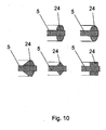
- FIG. 9 shows various embodiments of elevations 24 together with circumferential geometries or separately the stopper body 14, 15th form.
- the elevations 24 may be parabolic, kugelkalottenförmig, cylindrical, conical or frustoconical. There are also combinations of these geometries or other geometries conceivable.
- FIG. 10 shows various embodiments of circumferentially formed stopper body 14, 15. These may be parabolic, nikabitesfömig, rectangular, triangular or trapezoidal.
- FIG. 11 shows a membrane 5 for a hydraulic bearing 1 according to FIG. 1 ,
- the membrane 5 has a centrally arranged opening 11, which serves to equalize the pressure between the working space 3 and the compensation space 4.
- FIG. 12 shows a membrane 5 for a hydraulic bearing 1 according to FIG. 1 ,
- the membrane 5 has a centrally disposed opening 11, in which a disc 12 is arranged made of elastomeric material.
- FIG. 13 shows a membrane 5 for a hydraulic bearing 1 according to FIG. 1 ,
- the membrane 5 has a centrally disposed opening 11, in which a disc 12 is arranged made of elastomeric material, wherein in the disc 12, a slot 13 is arranged.
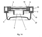
- FIG. 14 shows a membrane 5 for a hydraulic bearing 1 according to FIG. 1 , which is connected by an elastic connecting element 16 with the housing 2.
- FIG. 15 shows a circular membrane with a connecting element 16, consisting of several distributed over the circumference of the membrane 5 arranged webs 17.
- the starting point 18 is fixed to the diaphragm 5 and extends tangentially from the diaphragm 5 in the direction of the housing.
- the end point 19 of the webs 17 is fixed to the housing 2.
- the connecting element 16 is of the same material and formed integrally with the stop bodies 14, 15.
- the webs 17 are connected to each other at their end points 19 and can thereby be fixed in a form-fitting manner in the housing 2.
- FIG. 16 shows a membrane 5 according to FIG. 15 , In this embodiment, however, the membrane 5 has a rectangular base with rounded edges.
- the webs 17 are attached to the narrow sides of the membrane 5 in the region of the corners and are connected to one another at their end points 19.
Landscapes
- Engineering & Computer Science (AREA)
- General Engineering & Computer Science (AREA)
- Mechanical Engineering (AREA)
- Combined Devices Of Dampers And Springs (AREA)
- Magnetic Bearings And Hydrostatic Bearings (AREA)
Applications Claiming Priority (1)
| Application Number | Priority Date | Filing Date | Title |
|---|---|---|---|
| DE200710054882 DE102007054882A1 (de) | 2007-11-15 | 2007-11-15 | Hydrolager |
Publications (3)
| Publication Number | Publication Date |
|---|---|
| EP2060823A2 true EP2060823A2 (fr) | 2009-05-20 |
| EP2060823A3 EP2060823A3 (fr) | 2010-09-01 |
| EP2060823B1 EP2060823B1 (fr) | 2012-09-26 |
Family
ID=40386124
Family Applications (1)
| Application Number | Title | Priority Date | Filing Date |
|---|---|---|---|
| EP20080019669 Not-in-force EP2060823B1 (fr) | 2007-11-15 | 2008-11-11 | Support hydraulique |
Country Status (2)
| Country | Link |
|---|---|
| EP (1) | EP2060823B1 (fr) |
| DE (1) | DE102007054882A1 (fr) |
Cited By (4)
| Publication number | Priority date | Publication date | Assignee | Title |
|---|---|---|---|---|
| EP2253863A2 (fr) * | 2009-05-19 | 2010-11-24 | Carl Freudenberg KG | Support hydraulique |
| JP2013002456A (ja) * | 2011-06-13 | 2013-01-07 | Tokai Rubber Ind Ltd | 流体封入式防振装置 |
| WO2016026786A1 (fr) * | 2014-08-18 | 2016-02-25 | Boge Elastmetall Gmbh | Limitation de course d'une membrane |
| EP2531744B1 (fr) * | 2010-02-05 | 2017-11-01 | Cambridge Enterprise Limited | Dispositif hydraulique d'amortissement et d'inertie |
Families Citing this family (1)
| Publication number | Priority date | Publication date | Assignee | Title |
|---|---|---|---|---|
| DE102012006752A1 (de) | 2012-04-04 | 2013-10-10 | Carl Freudenberg Kg | Hydrolager |
Family Cites Families (3)
| Publication number | Priority date | Publication date | Assignee | Title |
|---|---|---|---|---|
| JPS5776340A (en) * | 1980-10-29 | 1982-05-13 | Toyoda Gosei Co Ltd | Liquid sealed-in vibration-proof apparatus |
| DE19829233A1 (de) * | 1998-06-30 | 2000-01-13 | Btr Avs Technical Centre Gmbh | Hydraulisch dämpfendes Motorlager |
| FR2798175B1 (fr) * | 1999-09-03 | 2002-04-19 | Peugeot Citroen Automobiles Sa | Clapet de support hydroelastique |
-
2007
- 2007-11-15 DE DE200710054882 patent/DE102007054882A1/de not_active Withdrawn
-
2008
- 2008-11-11 EP EP20080019669 patent/EP2060823B1/fr not_active Not-in-force
Cited By (4)
| Publication number | Priority date | Publication date | Assignee | Title |
|---|---|---|---|---|
| EP2253863A2 (fr) * | 2009-05-19 | 2010-11-24 | Carl Freudenberg KG | Support hydraulique |
| EP2531744B1 (fr) * | 2010-02-05 | 2017-11-01 | Cambridge Enterprise Limited | Dispositif hydraulique d'amortissement et d'inertie |
| JP2013002456A (ja) * | 2011-06-13 | 2013-01-07 | Tokai Rubber Ind Ltd | 流体封入式防振装置 |
| WO2016026786A1 (fr) * | 2014-08-18 | 2016-02-25 | Boge Elastmetall Gmbh | Limitation de course d'une membrane |
Also Published As
| Publication number | Publication date |
|---|---|
| DE102007054882A1 (de) | 2009-06-04 |
| EP2060823A3 (fr) | 2010-09-01 |
| EP2060823B1 (fr) | 2012-09-26 |
Similar Documents
| Publication | Publication Date | Title |
|---|---|---|
| DE102016001507B4 (de) | Schwingungstilger | |
| DE112009001615B4 (de) | Fluidgefüllter Schwingungsdämpfer | |
| DE2802896C2 (de) | Gummilager mit hydraulischer Dämpfung | |
| DE69930446T2 (de) | Flüssigkeitsabgedichtete, elastische Lagerung | |
| EP2060823B1 (fr) | Support hydraulique | |
| WO2017129531A1 (fr) | Palier hydraulique à vanne de dépression | |
| WO2018054603A1 (fr) | Soupape d'amortissement pour un amortisseur de vibrations | |
| EP0543082B1 (fr) | Manchon hydraulique à plusieurs compartiments | |
| DE60132168T2 (de) | Flüssigkeitsenthaltende und schwingungsdämpfende Vorrichtung | |
| WO2002014095A1 (fr) | Palier a amortissement hydraulique | |
| DE112022005660T5 (de) | Stossdämpfer | |
| DE102014210702A1 (de) | Frequenzabhängige Dämpfventilanordnung | |
| EP2032871B1 (fr) | Élément d'amortissement | |
| EP0307693A2 (fr) | Support de moteur à amortissement hydraulique et à deux chambres | |
| EP1481162B1 (fr) | Regulateur de pression pour une installation d'alimentation en carburant d'un moteur a combustion interne | |
| EP0756102B1 (fr) | Support pour moteurs de véhicules automobiles | |
| DE102019215555A1 (de) | Drosselstelle für einen Schwingungsdämpfer | |
| EP3380747B1 (fr) | Palier à amortissement hydraulique | |
| DE102016014315B4 (de) | Hydroelastisches Lager | |
| DE102004060499B4 (de) | Aggregatelager | |
| WO2003008836A1 (fr) | Unite ressort a gaz-amortisseur | |
| WO2001018424A1 (fr) | Dispositif de decouplage pour actionneurs | |
| DE102016015710B4 (de) | Schwingungstilger | |
| DE102016217114B4 (de) | Frequenzabhängige Dämpfventilanordnung | |
| DE102007015239B4 (de) | Elastische Lagerbuchse |
Legal Events
| Date | Code | Title | Description |
|---|---|---|---|
| PUAI | Public reference made under article 153(3) epc to a published international application that has entered the european phase |
Free format text: ORIGINAL CODE: 0009012 |
|
| AK | Designated contracting states |
Kind code of ref document: A2 Designated state(s): AT BE BG CH CY CZ DE DK EE ES FI FR GB GR HR HU IE IS IT LI LT LU LV MC MT NL NO PL PT RO SE SI SK TR |
|
| AX | Request for extension of the european patent |
Extension state: AL BA MK RS |
|
| PUAL | Search report despatched |
Free format text: ORIGINAL CODE: 0009013 |
|
| AK | Designated contracting states |
Kind code of ref document: A3 Designated state(s): AT BE BG CH CY CZ DE DK EE ES FI FR GB GR HR HU IE IS IT LI LT LU LV MC MT NL NO PL PT RO SE SI SK TR |
|
| AX | Request for extension of the european patent |
Extension state: AL BA MK RS |
|
| 17P | Request for examination filed |
Effective date: 20101014 |
|
| AKX | Designation fees paid |
Designated state(s): AT BE BG CH CY CZ DE DK EE ES FI FR GB GR HR HU IE IS IT LI LT LU LV MC MT NL NO PL PT RO SE SI SK TR |
|
| 17Q | First examination report despatched |
Effective date: 20110428 |
|
| GRAP | Despatch of communication of intention to grant a patent |
Free format text: ORIGINAL CODE: EPIDOSNIGR1 |
|
| GRAS | Grant fee paid |
Free format text: ORIGINAL CODE: EPIDOSNIGR3 |
|
| GRAA | (expected) grant |
Free format text: ORIGINAL CODE: 0009210 |
|
| AK | Designated contracting states |
Kind code of ref document: B1 Designated state(s): AT BE BG CH CY CZ DE DK EE ES FI FR GB GR HR HU IE IS IT LI LT LU LV MC MT NL NO PL PT RO SE SI SK TR |
|
| REG | Reference to a national code |
Ref country code: GB Ref legal event code: FG4D Free format text: NOT ENGLISH |
|
| REG | Reference to a national code |
Ref country code: CH Ref legal event code: EP |
|
| REG | Reference to a national code |
Ref country code: AT Ref legal event code: REF Ref document number: 577211 Country of ref document: AT Kind code of ref document: T Effective date: 20121015 |
|
| REG | Reference to a national code |
Ref country code: IE Ref legal event code: FG4D Free format text: LANGUAGE OF EP DOCUMENT: GERMAN |
|
| REG | Reference to a national code |
Ref country code: DE Ref legal event code: R096 Ref document number: 502008008248 Country of ref document: DE Effective date: 20121122 |
|
| PG25 | Lapsed in a contracting state [announced via postgrant information from national office to epo] |
Ref country code: HR Free format text: LAPSE BECAUSE OF FAILURE TO SUBMIT A TRANSLATION OF THE DESCRIPTION OR TO PAY THE FEE WITHIN THE PRESCRIBED TIME-LIMIT Effective date: 20120926 Ref country code: LT Free format text: LAPSE BECAUSE OF FAILURE TO SUBMIT A TRANSLATION OF THE DESCRIPTION OR TO PAY THE FEE WITHIN THE PRESCRIBED TIME-LIMIT Effective date: 20120926 Ref country code: NO Free format text: LAPSE BECAUSE OF FAILURE TO SUBMIT A TRANSLATION OF THE DESCRIPTION OR TO PAY THE FEE WITHIN THE PRESCRIBED TIME-LIMIT Effective date: 20121226 Ref country code: FI Free format text: LAPSE BECAUSE OF FAILURE TO SUBMIT A TRANSLATION OF THE DESCRIPTION OR TO PAY THE FEE WITHIN THE PRESCRIBED TIME-LIMIT Effective date: 20120926 |
|
| REG | Reference to a national code |
Ref country code: LT Ref legal event code: MG4D Effective date: 20120926 |
|
| REG | Reference to a national code |
Ref country code: NL Ref legal event code: VDEP Effective date: 20120926 |
|
| PG25 | Lapsed in a contracting state [announced via postgrant information from national office to epo] |
Ref country code: LV Free format text: LAPSE BECAUSE OF FAILURE TO SUBMIT A TRANSLATION OF THE DESCRIPTION OR TO PAY THE FEE WITHIN THE PRESCRIBED TIME-LIMIT Effective date: 20120926 Ref country code: GR Free format text: LAPSE BECAUSE OF FAILURE TO SUBMIT A TRANSLATION OF THE DESCRIPTION OR TO PAY THE FEE WITHIN THE PRESCRIBED TIME-LIMIT Effective date: 20121227 Ref country code: SE Free format text: LAPSE BECAUSE OF FAILURE TO SUBMIT A TRANSLATION OF THE DESCRIPTION OR TO PAY THE FEE WITHIN THE PRESCRIBED TIME-LIMIT Effective date: 20120926 Ref country code: SI Free format text: LAPSE BECAUSE OF FAILURE TO SUBMIT A TRANSLATION OF THE DESCRIPTION OR TO PAY THE FEE WITHIN THE PRESCRIBED TIME-LIMIT Effective date: 20120926 |
|
| PG25 | Lapsed in a contracting state [announced via postgrant information from national office to epo] |
Ref country code: NL Free format text: LAPSE BECAUSE OF FAILURE TO SUBMIT A TRANSLATION OF THE DESCRIPTION OR TO PAY THE FEE WITHIN THE PRESCRIBED TIME-LIMIT Effective date: 20120926 Ref country code: EE Free format text: LAPSE BECAUSE OF FAILURE TO SUBMIT A TRANSLATION OF THE DESCRIPTION OR TO PAY THE FEE WITHIN THE PRESCRIBED TIME-LIMIT Effective date: 20120926 Ref country code: ES Free format text: LAPSE BECAUSE OF FAILURE TO SUBMIT A TRANSLATION OF THE DESCRIPTION OR TO PAY THE FEE WITHIN THE PRESCRIBED TIME-LIMIT Effective date: 20130106 Ref country code: RO Free format text: LAPSE BECAUSE OF FAILURE TO SUBMIT A TRANSLATION OF THE DESCRIPTION OR TO PAY THE FEE WITHIN THE PRESCRIBED TIME-LIMIT Effective date: 20120926 Ref country code: IS Free format text: LAPSE BECAUSE OF FAILURE TO SUBMIT A TRANSLATION OF THE DESCRIPTION OR TO PAY THE FEE WITHIN THE PRESCRIBED TIME-LIMIT Effective date: 20130126 Ref country code: CZ Free format text: LAPSE BECAUSE OF FAILURE TO SUBMIT A TRANSLATION OF THE DESCRIPTION OR TO PAY THE FEE WITHIN THE PRESCRIBED TIME-LIMIT Effective date: 20120926 |
|
| BERE | Be: lapsed |
Owner name: CARL FREUDENBERG K.G. Effective date: 20121130 |
|
| PG25 | Lapsed in a contracting state [announced via postgrant information from national office to epo] |
Ref country code: PL Free format text: LAPSE BECAUSE OF FAILURE TO SUBMIT A TRANSLATION OF THE DESCRIPTION OR TO PAY THE FEE WITHIN THE PRESCRIBED TIME-LIMIT Effective date: 20120926 Ref country code: SK Free format text: LAPSE BECAUSE OF FAILURE TO SUBMIT A TRANSLATION OF THE DESCRIPTION OR TO PAY THE FEE WITHIN THE PRESCRIBED TIME-LIMIT Effective date: 20120926 Ref country code: PT Free format text: LAPSE BECAUSE OF FAILURE TO SUBMIT A TRANSLATION OF THE DESCRIPTION OR TO PAY THE FEE WITHIN THE PRESCRIBED TIME-LIMIT Effective date: 20130128 Ref country code: CY Free format text: LAPSE BECAUSE OF FAILURE TO SUBMIT A TRANSLATION OF THE DESCRIPTION OR TO PAY THE FEE WITHIN THE PRESCRIBED TIME-LIMIT Effective date: 20120926 |
|
| REG | Reference to a national code |
Ref country code: CH Ref legal event code: PL |
|
| PG25 | Lapsed in a contracting state [announced via postgrant information from national office to epo] |
Ref country code: CH Free format text: LAPSE BECAUSE OF NON-PAYMENT OF DUE FEES Effective date: 20121130 Ref country code: BG Free format text: LAPSE BECAUSE OF FAILURE TO SUBMIT A TRANSLATION OF THE DESCRIPTION OR TO PAY THE FEE WITHIN THE PRESCRIBED TIME-LIMIT Effective date: 20121226 Ref country code: DK Free format text: LAPSE BECAUSE OF FAILURE TO SUBMIT A TRANSLATION OF THE DESCRIPTION OR TO PAY THE FEE WITHIN THE PRESCRIBED TIME-LIMIT Effective date: 20120926 Ref country code: LI Free format text: LAPSE BECAUSE OF NON-PAYMENT OF DUE FEES Effective date: 20121130 |
|
| PLBE | No opposition filed within time limit |
Free format text: ORIGINAL CODE: 0009261 |
|
| STAA | Information on the status of an ep patent application or granted ep patent |
Free format text: STATUS: NO OPPOSITION FILED WITHIN TIME LIMIT |
|
| REG | Reference to a national code |
Ref country code: IE Ref legal event code: MM4A |
|
| PG25 | Lapsed in a contracting state [announced via postgrant information from national office to epo] |
Ref country code: BE Free format text: LAPSE BECAUSE OF NON-PAYMENT OF DUE FEES Effective date: 20121130 Ref country code: IT Free format text: LAPSE BECAUSE OF FAILURE TO SUBMIT A TRANSLATION OF THE DESCRIPTION OR TO PAY THE FEE WITHIN THE PRESCRIBED TIME-LIMIT Effective date: 20120926 |
|
| 26N | No opposition filed |
Effective date: 20130627 |
|
| REG | Reference to a national code |
Ref country code: DE Ref legal event code: R097 Ref document number: 502008008248 Country of ref document: DE Effective date: 20130627 |
|
| PG25 | Lapsed in a contracting state [announced via postgrant information from national office to epo] |
Ref country code: IE Free format text: LAPSE BECAUSE OF NON-PAYMENT OF DUE FEES Effective date: 20121111 |
|
| PG25 | Lapsed in a contracting state [announced via postgrant information from national office to epo] |
Ref country code: MT Free format text: LAPSE BECAUSE OF FAILURE TO SUBMIT A TRANSLATION OF THE DESCRIPTION OR TO PAY THE FEE WITHIN THE PRESCRIBED TIME-LIMIT Effective date: 20120926 |
|
| PGFP | Annual fee paid to national office [announced via postgrant information from national office to epo] |
Ref country code: GB Payment date: 20131120 Year of fee payment: 6 Ref country code: DE Payment date: 20131122 Year of fee payment: 6 |
|
| PGFP | Annual fee paid to national office [announced via postgrant information from national office to epo] |
Ref country code: FR Payment date: 20131118 Year of fee payment: 6 |
|
| PG25 | Lapsed in a contracting state [announced via postgrant information from national office to epo] |
Ref country code: TR Free format text: LAPSE BECAUSE OF FAILURE TO SUBMIT A TRANSLATION OF THE DESCRIPTION OR TO PAY THE FEE WITHIN THE PRESCRIBED TIME-LIMIT Effective date: 20120926 Ref country code: MC Free format text: LAPSE BECAUSE OF NON-PAYMENT OF DUE FEES Effective date: 20121130 |
|
| PG25 | Lapsed in a contracting state [announced via postgrant information from national office to epo] |
Ref country code: LU Free format text: LAPSE BECAUSE OF NON-PAYMENT OF DUE FEES Effective date: 20121111 |
|
| PG25 | Lapsed in a contracting state [announced via postgrant information from national office to epo] |
Ref country code: HU Free format text: LAPSE BECAUSE OF FAILURE TO SUBMIT A TRANSLATION OF THE DESCRIPTION OR TO PAY THE FEE WITHIN THE PRESCRIBED TIME-LIMIT Effective date: 20081111 |
|
| REG | Reference to a national code |
Ref country code: AT Ref legal event code: MM01 Ref document number: 577211 Country of ref document: AT Kind code of ref document: T Effective date: 20131111 |
|
| PG25 | Lapsed in a contracting state [announced via postgrant information from national office to epo] |
Ref country code: AT Free format text: LAPSE BECAUSE OF NON-PAYMENT OF DUE FEES Effective date: 20131111 |
|
| REG | Reference to a national code |
Ref country code: DE Ref legal event code: R119 Ref document number: 502008008248 Country of ref document: DE |
|
| GBPC | Gb: european patent ceased through non-payment of renewal fee |
Effective date: 20141111 |
|
| REG | Reference to a national code |
Ref country code: FR Ref legal event code: ST Effective date: 20150731 |
|
| PG25 | Lapsed in a contracting state [announced via postgrant information from national office to epo] |
Ref country code: DE Free format text: LAPSE BECAUSE OF NON-PAYMENT OF DUE FEES Effective date: 20150602 Ref country code: GB Free format text: LAPSE BECAUSE OF NON-PAYMENT OF DUE FEES Effective date: 20141111 |
|
| PG25 | Lapsed in a contracting state [announced via postgrant information from national office to epo] |
Ref country code: FR Free format text: LAPSE BECAUSE OF NON-PAYMENT OF DUE FEES Effective date: 20141201 |