EP2060837A2 - Valve de réglage de débit - Google Patents
Valve de réglage de débit Download PDFInfo
- Publication number
- EP2060837A2 EP2060837A2 EP08019670A EP08019670A EP2060837A2 EP 2060837 A2 EP2060837 A2 EP 2060837A2 EP 08019670 A EP08019670 A EP 08019670A EP 08019670 A EP08019670 A EP 08019670A EP 2060837 A2 EP2060837 A2 EP 2060837A2
- Authority
- EP
- European Patent Office
- Prior art keywords
- control valve
- flow control
- hollow piston
- flow
- valve according
- Prior art date
- Legal status (The legal status is an assumption and is not a legal conclusion. Google has not performed a legal analysis and makes no representation as to the accuracy of the status listed.)
- Withdrawn
Links
Images


Classifications
-
- B—PERFORMING OPERATIONS; TRANSPORTING
- B63—SHIPS OR OTHER WATERBORNE VESSELS; RELATED EQUIPMENT
- B63B—SHIPS OR OTHER WATERBORNE VESSELS; EQUIPMENT FOR SHIPPING
- B63B13/00—Conduits for emptying or ballasting; Self-bailing equipment; Scuppers
- B63B13/02—Ports for passing water through vessels' sides
-
- F—MECHANICAL ENGINEERING; LIGHTING; HEATING; WEAPONS; BLASTING
- F16—ENGINEERING ELEMENTS AND UNITS; GENERAL MEASURES FOR PRODUCING AND MAINTAINING EFFECTIVE FUNCTIONING OF MACHINES OR INSTALLATIONS; THERMAL INSULATION IN GENERAL
- F16K—VALVES; TAPS; COCKS; ACTUATING-FLOATS; DEVICES FOR VENTING OR AERATING
- F16K31/00—Actuating devices; Operating means; Releasing devices
- F16K31/12—Actuating devices; Operating means; Releasing devices actuated by fluid
- F16K31/122—Actuating devices; Operating means; Releasing devices actuated by fluid the fluid acting on a piston
-
- F—MECHANICAL ENGINEERING; LIGHTING; HEATING; WEAPONS; BLASTING
- F16—ENGINEERING ELEMENTS AND UNITS; GENERAL MEASURES FOR PRODUCING AND MAINTAINING EFFECTIVE FUNCTIONING OF MACHINES OR INSTALLATIONS; THERMAL INSULATION IN GENERAL
- F16K—VALVES; TAPS; COCKS; ACTUATING-FLOATS; DEVICES FOR VENTING OR AERATING
- F16K51/00—Other details not peculiar to particular types of valves or cut-off apparatus
- F16K51/02—Other details not peculiar to particular types of valves or cut-off apparatus specially adapted for high-vacuum installations
Definitions
- the invention relates to a flow control valve having the features specified in claim 1.
- flooded rooms include, for example, weapons ejection pipes.
- the weapons e.g. Torpedoes
- the ejection tube is flooded by opening a shut-off valve, wherein in the shortest possible time a pressure equalization between the interior of the ejection tube and the ambient pressure of the submarine is sought.
- the very large difference in pressure between the interior of the ejection tube and the outer environment of the submarine may cause the water jet flowing into the ejection tube through the shut-off valve to have such a large momentum effect that it flows into the ejection tube weapon is damaged or destroyed.
- the object of the invention is to provide a valve with which a space which is under negative pressure with respect to its surroundings can be flooded in a short time, wherein it should be ensured that objects located in the space to be flooded not be damaged by the pulse action of the fluid flowing through the valve.
- the flow control valve according to the invention is provided for flooding a negative pressure with respect to its surroundings and in particular for flooding a container on a submarine.
- the flow control valve is provided with a shut-off device, wherein it has means for controlling the shut-off device.
- the basic idea of the invention is therefore to provide a valve with which the flow through the valve can be regulated and thus can be kept substantially constant independently of the pressure prevailing on the input side of the valve.
- the flow rate through the flow control valve is suitably adjusted so that the space to be flooded or container is flooded in a given time, the flow through the flow control valve, however, is limited so that the impulse from the fluid flowing into the container a in can not damage the space or container.
- the flow control valve according to the invention thus serves not only as a pressure reducer, but also as a shut-off valve, since it has a shut-off device in addition to the flow control valve.
- a space to be flooded can be closed off from its surroundings in a pressure-tight manner before being flooded.
- the means for controlling the shut-off device allow a closing body of the flow control valve to move into a flow path by the flow control valve releasing and closing this flow path position.
- the flow control valve has at least one flow outlet closed at the beginning of a flow control process.
- the flow outlet is fully opened at the beginning of a flow control, so at the beginning of the flow control process at the flow outlet volume flow peaks can be avoided, which could otherwise lead to damage or destruction of an object that is located in the is located above the flow control valve to be flooded room.
- the closing body of the flow control valve is preferably formed by a slide.
- This slide can be designed and arranged such that it closes an inlet opening formed on a valve housing of the flow control valve in a slide position and releases it in a further slide position.
- an embodiment of the slide is preferred in which the inlet opening of the flow control valve is formed on the slide.
- the slider is preferably formed as a hollow body which forms part of the flow path through the flow control valve.
- the inlet opening of the flow control valve can be released in this embodiment of the slide by the slide is moved out of the valve housing of the flow control valve. In a closed position, the inlet opening formed on the slide is expediently closed by a region of the valve housing in a state of the slide retracted in the valve housing.
- the flow control valve according to the invention advantageously has a pressure compensator with a hollow piston.
- This hollow piston is preferably telescopic and particularly preferably designed in two parts telescopic.
- the hollow piston two in one another having gripping piston parts which are displaceable in a limited area relative to each other.
- the hollow piston thus forms a control throttle with which the opening cross section of a flow outlet formed on the valve housing of the flow control valve can be changed in dependence on the pressure prevailing on the input side of the flow outlet.
- the change in the opening cross section of the flow outlet takes place in this embodiment by the extension and retraction of at least a portion of the telescoping hollow piston and, consequently, by changing the position of a control edge formed by the hollow piston relative to the flow outlet of the flow control valve.
- the hollow piston forms part of a flow path through the flow control valve.
- the hollow piston preferably has on the circumference at least one flow inlet opening and at least one flow outlet opening.
- the flow outlet opening of the hollow piston can be arranged corresponding to the position of a flow outlet formed on the valve housing of the flow control valve and be moved by retracting and retracting the hollow piston in a free opening cross section of the flow outlet changing position, the flow cross section of the flow outlet in a position of the hollow piston completely closed is and is completely released in another position of the hollow piston.
- the slide forms part of the pressure compensator of the flow control valve according to the invention.
- the pressure compensator not only forms a control device for regulating the flow rate through the valve, but advantageously also serves as a shut-off device with which the flow control valve can be closed and opened.
- the pressure compensator is movable by means of suitable control means in the valve housing such that the slide in a the flow inlet of the flow control valve releasing and a position closing the flow inlet of the flow control valve can be moved.
- the slide is expediently designed as a hollow cylinder and forms part of the hollow piston.
- the slide preferably forms one of the two interengaging piston parts, on the circumferential side of which at least one flow inlet opening of the hollow piston is arranged.
- This flow inlet opening can also form the flow inlet of the entire flow control valve, which can be opened by moving the hollow piston out of the valve housing and can be closed again by moving it back into the valve housing.
- a prestressed compression spring is arranged in the hollow piston of the pressure compensator. This is expediently supported on the two mutually facing end faces of the hollow piston.
- the compression spring forms in this embodiment, together with the hollow piston, the pressure compensator and is used for telescoping or moving apart of the two interlocking piston halves of the hollow piston.
- the hollow piston In order to be able to move the hollow piston in the valve housing into a position which opens the flow inlet opening of the hollow piston, the hollow piston is preferably displaceable in a fluidically displaceable manner.
- the hollow piston can be moved pneumatically in this embodiment, but preferably hydraulically actuated in the direction of its longitudinal axis in the valve housing.
- a piston-cylinder arrangement is advantageously provided, wherein the cylinder preferably forms part of the hollow piston.
- the piston of the piston-cylinder assembly is fixedly arranged in this embodiment of the flow control valve according to the invention in the valve housing, while the cylinder together with the hollow piston in the valve housing by pressurizing a chamber of the cylinder with a pressure medium, preferably with a hydraulic fluid, is movable.
- the hollow piston is displaceable mechanically actuated in the valve housing.
- the movement of the hollow piston for example, via a lever arrangement or via a spindle drive.
- the flow control valve expediently has a lockable bypass line via which the interior of the hollow piston can be fluidly connected to the environment of the space to be flooded.
- a lockable bypass line via which the interior of the hollow piston can be fluidly connected to the environment of the space to be flooded.
- a baffle plate is advantageously arranged downstream of the flow outlet opening of the pressure compensator. This baffle plate is intended to catch the liquid jet emerging from the flow outlet opening of the pressure compensator, so that it can not directly hit any object arranged in the space to be flooded.
- a further preferred embodiment of the flow control valve according to the invention provides a locking device which holds the hollow piston in a position closing the flow control valve.
- a bolt is provided, the one from the valve housing by means of a compression spring whichbewegbares piston part of the hollow piston in a closed position of the flow control valve against the spring force of the compression spring positively holds.
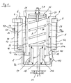
- the flow control valve has a hollow cylindrical valve housing 2 with an open and a closed side.
- the valve housing 2 engages via an opening of an outer wall 4 in a space which is pressure-tightly sealed by means of the flow control valve and subsequently flooded.
- the valve housing 2 is supported on the outer side of the outer wall 4 via a collar 6, which extends circumferentially outwardly at its open end and outwards, by means of which it is fixedly connected to the outer wall 4.
- a hollow piston 8 is arranged, which is displaceable in the direction of a longitudinal axis A of the valve housing 2.
- the hollow piston 8 is formed in two parts, wherein a hollow cylindrical hollow piston part 8a engages in a likewise hollow cylindrical Hohlkoben 8b.
- the hollow piston parts 8a and 8b are in the direction of a longitudinal axis A of the hollow piston 8 relative to each other movable, wherein the possible range of movement of the two hollow piston parts 8a and 8b is limited by an open at the open end of the hollow piston member 8a outwardly directed collar 10 and at the open end of the hollow piston member 8b inwardly directed collar 12.
- a hollow cylinder 14 is arranged, in which a piston 16 engages.
- This piston 16 is attached to the closed end of the valve housing 2.
- the engaging in the hollow cylinder 14 end of the piston 16 is formed radially widened, wherein the outer cross section of this extended portion of the piston 16 with the inner cross section of the hollow cylinder 14 corresponds.
- the radially expanded region of the piston 16 divides the hollow cylinder 14 into a first hollow cylinder chamber 14a adjoining the free end of the piston 16 and a second hollow cylinder chamber 14b peripherally surrounding the piston 16.
- the hollow cylinder 14 forms together with the piston 16 a piston-cylinder arrangement with which the hollow piston 8 is hydraulically movable in the valve housing 2, wherein the hollow piston 8 can be partially moved out of the valve housing 2.
- the conduit 18 opens into the first hollow cylinder chamber 14a, while the conduit 20 opens into the second hollow cylinder chamber 14b.
- the hollow cylinder chamber 14a or the hollow cylinder chamber 14b can be printed.
- the hollow piston 8 In its retracted into the valve housing 2 state, the hollow piston 8 is arranged almost completely in the valve housing 2, wherein, however, that closed end 24 of the hollow piston part 8a. is radially expanded relative to the inner cross section of the valve housing 2 and forms a circumferential contact shoulder, which rests in the retracted state on the outer side of the collar 6 of the valve housing 2. About a arranged in close proximity to the end 24 in a circumferential groove sealing ring 26 of the hollow piston 8 is sealed against the inner wall of the valve housing 2.
- the 4/3-way valve is set such that a hydraulic fluid can flow via the line 18 into the hollow cylinder chamber 14 a.
- the hollow piston 8 can be retracted into the valve housing 2 by the 4/3-way valve is placed so that the hydraulic fluid can flow via the line 20 into the hollow cylinder chamber 14 b.
- the hollow piston part 8a has flow inlet openings 28 distributed over its circumference. These are arranged on the hollow piston part 8a such that they are in the extended state of the hollow piston 8 outside of the valve housing 2, however, are closed in the retracted state of the hollow piston 8 of the inner wall of the valve housing 2.
- a fluid from the outer environment of the flow control valve according to the invention can flow into the interior of the hollow piston 8.
- the hollow piston part 8a forms a closing body of the flow control valve designed as a slide.
- the flow inlet openings (28) form throttles which generate a pressure difference between the external environment of the flow control valve and the interior of the hollow piston 8 which is proportional to the volume flow flowing into the interior of the hollow piston 8.
- the hollow piston part 8a In order to be able to pass on the fluid which has flowed into the interior of the hollow piston 8 via the flow inlet openings 28 from there to flow outlets 30 of the flow control valve, which are arranged distributed circumferentially on the valve housing 2, the hollow piston part 8a has over distributed around its periphery Strömungsauslassö réelleen 32. However, since the hollow piston 8 forms part of a pressure compensator, its flow outlet openings 32 are not always connected in a flow-conducting manner to the flow outlets 30 formed on the valve housing 2. Such a line connection is made possible by the telescoping of the hollow piston part 8a by means of a pressure spring 34 arranged in the interior of the hollow piston 8, which together with the hollow piston 8 forms the pressure compensator.
- Trained as a helical spring compression spring 34 is supported in the hollow piston 8 on the one hand on the inner end face of the hollow piston part 8b and on the other hand on a arranged on the inside of the end 24 of the hollow piston part 8a shim 36.
- the position of the shim 36 is adjustable in the direction of the longitudinal axis A via an adjusting screw 38, whereby the bias of the compression spring 34 is changeable.
- the hollow piston part 8a with the flow outlet openings 32 formed thereon forms, together with the valve housing 2, a regulating throttle with which the opening cross section of the flow outlets 30 of the flow control valve formed on the valve housing 2 can be changed as a function of the position of the hollow piston 8.
- the position of the upper hollow piston part 8a adjusts itself due to the balance of forces on the hollow piston 8, wherein the equilibrium of forces from the pressure difference between the pressure in the hollow piston 8 and on the closed end 24 of the hollow piston part 8a load-bearing external pressure and dependent on the position of the hollow piston 8 Spring force of the compression spring 34 results.
- Fig. 1 shows the flow control valve with fully retracted in the valve housing 2 hollow piston 8. In this position, a relation to the outside environment under vacuum standing space pressure-tight from closed the flow control valve. The pressure prevailing in the external environment of the flow control valve presses on the outside of the end 24 of the hollow piston part 8a. If the pressure force thus exerted on the hollow piston part 8a exceeds the spring force of the compression spring 24 acting in the opposite direction, then the hollow piston 8 can be held solely by the external pressure in a position closing the flow control valve. However, this is not the case when the spring force of the compression spring 34 exceeds the externally acting on the hollow piston part 8a pressure force.
- a lock with a latch 40 is provided which holds the hollow piston part 8a in a position closing the flow control valve.
- the bolt 40 is hook-shaped and engages behind the collar 10 of the hollow piston part 8a, wherein it is held by a leaf spring 42 in this position.
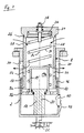
- the 4/3-way valve is set such that hydraulic fluid can flow via the line 18 into the hollow cylinder chamber 14a ( Fig.2 ).
- the hollow piston part 8b is moved together with the hollow piston part 8a in a direction away from the closed end face of the valve housing 2, the hollow piston part 8b moves the latch 40 against the force of the leaf spring 42 in a hollow piston part 8a releasing position.
- a bypass line 44 is provided, via which the interior of the valve housing 2 with the outside environment of the space to be flooded is conductively connected. ( Fig. 1 ).
- the bypass line 44 opens into the valve housing 2 in an annular chamber 46, which is arranged directly adjacent to the flow outlet openings 32 of the hollow piston part 8a when the hollow piston 8 is retracted.
- a first in the bypass line 44th arranged shut-off valve 48 is opened.
- a pressure equalization is created between the external pressure acting on the end of the hollow piston part 8a and the internal pressure in the hollow piston 8a, as a result of which the hollow piston 8 can finally be moved out of the valve housing 2.
- the hollow piston part 8a is moved out of the hollow piston part 8b such that the flow outlet openings 32 of the hollow piston part 8a are arranged corresponding to the flow outlets 30 of the valve housing 2, wherein the fluid the interior of the hollow piston 8 can flow through the outlet 30 of the valve body over the entire cross section of the outlet openings 32 of the hollow piston part 8a ( Fig. 4 ).
- baffles 50 are provided on the outside of the flow outlets 30, which initially collect the fluid flow discharged from a flow outlet 30, and then over the baffle plate 50 trained outlet openings 42 lead into the space to be flooded ( Fig.1 ).
Landscapes
- Engineering & Computer Science (AREA)
- General Engineering & Computer Science (AREA)
- Mechanical Engineering (AREA)
- Chemical & Material Sciences (AREA)
- Combustion & Propulsion (AREA)
- Ocean & Marine Engineering (AREA)
- Fluid-Driven Valves (AREA)
- Safety Valves (AREA)
- Magnetically Actuated Valves (AREA)
Applications Claiming Priority (1)
| Application Number | Priority Date | Filing Date | Title |
|---|---|---|---|
| DE102007054781A DE102007054781A1 (de) | 2007-11-16 | 2007-11-16 | Stromregelventil |
Publications (2)
| Publication Number | Publication Date |
|---|---|
| EP2060837A2 true EP2060837A2 (fr) | 2009-05-20 |
| EP2060837A3 EP2060837A3 (fr) | 2012-01-18 |
Family
ID=40352636
Family Applications (1)
| Application Number | Title | Priority Date | Filing Date |
|---|---|---|---|
| EP08019670A Withdrawn EP2060837A3 (fr) | 2007-11-16 | 2008-11-11 | Valve de réglage de débit |
Country Status (3)
| Country | Link |
|---|---|
| EP (1) | EP2060837A3 (fr) |
| KR (1) | KR101096007B1 (fr) |
| DE (1) | DE102007054781A1 (fr) |
Cited By (3)
| Publication number | Priority date | Publication date | Assignee | Title |
|---|---|---|---|---|
| CN101649922B (zh) * | 2009-09-10 | 2011-02-02 | 李镜辉 | 一种延时阀 |
| CN108216535A (zh) * | 2018-01-12 | 2018-06-29 | 河海大学常州校区 | 一种水下机器人浮沉装置和浮沉方法 |
| CN113830273A (zh) * | 2021-10-22 | 2021-12-24 | 重庆前卫科技集团有限公司 | 进水装置及其安装结构 |
Families Citing this family (1)
| Publication number | Priority date | Publication date | Assignee | Title |
|---|---|---|---|---|
| DE102012208627A1 (de) * | 2012-05-23 | 2013-11-28 | Thyssenkrupp Marine Systems Gmbh | Unterseeboot |
Family Cites Families (6)
| Publication number | Priority date | Publication date | Assignee | Title |
|---|---|---|---|---|
| GB291861A (en) * | 1927-03-08 | 1928-06-08 | Vickers Ltd | Improvements in or relating to telemotor operated liquid discharge and admission valves |
| DE1209386B (de) * | 1960-11-15 | 1966-01-20 | Asea Ab | Druckmittelbetaetigtes Ventil |
| DE2817851A1 (de) * | 1978-04-24 | 1979-10-31 | Gemmecke Kurt Ing Grad | Absperrventil fuer heisse gase |
| JPS58156185U (ja) | 1982-04-15 | 1983-10-18 | 油研工業株式会社 | 流体制御装置 |
| FI107891B (fi) | 1998-03-30 | 2001-10-31 | Sandvik Tamrock Oy | Painenestekäyttöinen iskulaite |
| FR2841629B1 (fr) * | 2002-06-28 | 2004-07-30 | Thales Sa | Vanne fluidique a hysteresis et procede d'utlisation |
-
2007
- 2007-11-16 DE DE102007054781A patent/DE102007054781A1/de not_active Ceased
-
2008
- 2008-11-11 EP EP08019670A patent/EP2060837A3/fr not_active Withdrawn
- 2008-11-14 KR KR1020080113073A patent/KR101096007B1/ko not_active Expired - Fee Related
Cited By (5)
| Publication number | Priority date | Publication date | Assignee | Title |
|---|---|---|---|---|
| CN101649922B (zh) * | 2009-09-10 | 2011-02-02 | 李镜辉 | 一种延时阀 |
| CN108216535A (zh) * | 2018-01-12 | 2018-06-29 | 河海大学常州校区 | 一种水下机器人浮沉装置和浮沉方法 |
| CN108216535B (zh) * | 2018-01-12 | 2019-12-10 | 河海大学常州校区 | 一种水下机器人浮沉装置和浮沉方法 |
| CN113830273A (zh) * | 2021-10-22 | 2021-12-24 | 重庆前卫科技集团有限公司 | 进水装置及其安装结构 |
| CN113830273B (zh) * | 2021-10-22 | 2022-08-09 | 重庆前卫科技集团有限公司 | 进水装置及其安装结构 |
Also Published As
| Publication number | Publication date |
|---|---|
| DE102007054781A1 (de) | 2009-05-28 |
| KR101096007B1 (ko) | 2011-12-19 |
| KR20090050973A (ko) | 2009-05-20 |
| EP2060837A3 (fr) | 2012-01-18 |
Similar Documents
| Publication | Publication Date | Title |
|---|---|---|
| DE2419311A1 (de) | Mit hoher geschwindigkeit arbeitendes ventil | |
| DE102015016846A1 (de) | Ventil, insbesondere 4/2-Wegeschieberventil | |
| EP2153072B1 (fr) | Agencement de soupape avec un manometre a piston individuel et une soupape de frein d'abaissement | |
| DE102010021202A1 (de) | Lasthalteventil mit Druckbegrenzungsfunktion | |
| EP2060837A2 (fr) | Valve de réglage de débit | |
| EP0902194B1 (fr) | Soupape à maintien de charge | |
| DE102012015356A1 (de) | Ventil, insbesondere vorgesteuertes Proportional-Wegesitzventil | |
| DE102012015354A1 (de) | Ventil, insbesondere vorgesteuertes Proportional-Wegesitzventil | |
| DE2948639C2 (de) | Absperr- und Regelventil | |
| DE3218527C2 (fr) | ||
| EP3037679A1 (fr) | Actionneur fluidique | |
| EP2124012B1 (fr) | Dispositif lanceur pour des corps immergés | |
| DE102014016296B4 (de) | Hydraulikanordnung zur Steuerung wenigstens einer, insbesondere doppelt wirkenden, hydraulischen Kolben-Zylinder-Anordnung und Vorrichtung zum Fügen und/oder Stanzen und/oder Schweißen mehrerer Partner umfassend eine entsprechende Hydraulikanordnung | |
| EP1178223A2 (fr) | Vérin hydraulique | |
| DE102014222326B4 (de) | Hydraulikanordnung | |
| DE2038813C2 (de) | Druckmittelbetätigtes Mehrwegeventil in Schieberbauart | |
| DE102008059437B3 (de) | Hydraulisches Steuerventil mit zwei Steuerkolben für einen einseitig arbeitenden Differentialzylinder | |
| DE2448436A1 (de) | Ventil | |
| DE1550732A1 (de) | Zylinder- und Kolbenaufbau | |
| DE3828025A1 (de) | Daempfungssystem fuer fluid-zylinder | |
| DE102015015858A1 (de) | Überwachungseinrichtung für Werkzeugrevolver | |
| DE102021126389A1 (de) | Fluidbetriebenes Bewegungssystem, Betätigungszylinder zum Öffnen und Schließen und Verfahren zum Bewegen | |
| DE102005047823A1 (de) | Eilgangzylindereinheit | |
| EP2666711B1 (fr) | Submersible | |
| EP0227854B1 (fr) | Dispositif de réduction de pression |
Legal Events
| Date | Code | Title | Description |
|---|---|---|---|
| PUAI | Public reference made under article 153(3) epc to a published international application that has entered the european phase |
Free format text: ORIGINAL CODE: 0009012 |
|
| AK | Designated contracting states |
Kind code of ref document: A2 Designated state(s): AT BE BG CH CY CZ DE DK EE ES FI FR GB GR HR HU IE IS IT LI LT LU LV MC MT NL NO PL PT RO SE SI SK TR |
|
| AX | Request for extension of the european patent |
Extension state: AL BA MK RS |
|
| PUAL | Search report despatched |
Free format text: ORIGINAL CODE: 0009013 |
|
| AK | Designated contracting states |
Kind code of ref document: A3 Designated state(s): AT BE BG CH CY CZ DE DK EE ES FI FR GB GR HR HU IE IS IT LI LT LU LV MC MT NL NO PL PT RO SE SI SK TR |
|
| AX | Request for extension of the european patent |
Extension state: AL BA MK RS |
|
| RIC1 | Information provided on ipc code assigned before grant |
Ipc: F16K 31/122 20060101AFI20111212BHEP |
|
| AKY | No designation fees paid | ||
| REG | Reference to a national code |
Ref country code: DE Ref legal event code: R108 |
|
| 17P | Request for examination filed |
Effective date: 20120716 |
|
| RBV | Designated contracting states (corrected) |
Designated state(s): AT BE BG CH CY CZ DE DK EE ES FI FR GB GR HR HU IE IS IT LI LT LU LV MC MT NL NO PL PT RO SE SI SK TR |
|
| REG | Reference to a national code |
Ref country code: DE Ref legal event code: R108 Effective date: 20120926 |
|
| RAP1 | Party data changed (applicant data changed or rights of an application transferred) |
Owner name: THYSSENKRUPP MARINE SYSTEMS GMBH |
|
| RIC1 | Information provided on ipc code assigned before grant |
Ipc: B63B 13/02 20060101ALI20130903BHEP Ipc: F16K 31/122 20060101AFI20130903BHEP |
|
| GRAP | Despatch of communication of intention to grant a patent |
Free format text: ORIGINAL CODE: EPIDOSNIGR1 |
|
| INTG | Intention to grant announced |
Effective date: 20131022 |
|
| RIN1 | Information on inventor provided before grant (corrected) |
Inventor name: KOERNER, ROLAND |
|
| STAA | Information on the status of an ep patent application or granted ep patent |
Free format text: STATUS: THE APPLICATION IS DEEMED TO BE WITHDRAWN |
|
| 18D | Application deemed to be withdrawn |
Effective date: 20140304 |